~ Final work post.
~ post date: 2017.2.1, recent update: 2017.6.28
I have a vision of bio/technologically literate people who live in symbiosis with nature and machines. Their living vessels harvest and provide electricity, water, food, clean air, and comfort. In exchange, these people do people stuff: breathe, wash clothing/ dishes, excrete things and their vessels love them for it…
On my journey to resolve this vision, I would like to investigate low-cost biological approaches for energy production. That starts with the Sun. The Sun is the ultimate source of energy for almost all life on Earth. Solar energy is carbon-free, everywhere, and abundant. Nature demonstrates the potentials by utilizing solar energy through the process of photosynthesis. Indeed, that potential has been developed into a number of synthetic techniques, i.e. solar cells, to emulate photosynthesis to generate electricity, often to greater efficiencies. One branch of this research seeks to develop similarly efficient light harvesting bioelectrochemical processes replete with interesting advantages over synthetic approaches in that the photosensitive components are assembled and maintained by living organisms that self-repair, reproduce and store energy for power generation in times without sunlight. Among the forms this research has taken is biophotovoltaic devices, i.e. algae based solar panels, and microbial fuel cells. "Life depends on the transfer of electrons between different biochemical intermediates to discharge or capture energy, or drive chemical change. The ability of certain microbes to facilitate the direct and/or indirect transfer of electrons outside of the cell (exoelectrogenic activity), which can then be harvested for reductive power, has driven the development of a variety of devices in which living organisms directly generate electrical power, which may also be coupled to separate reductive processes in the devices (collectively known as bioelectrochemical systems)." -Energy Environ. Sci., 2015, 8, 1092. Exoelectrogens metabolize organic substrates (released by the plants) and donate electrons to conductive materials (ie electrodes). The captured electrons are then directed through an electrical circuit to reduce an electron acceptor (i.e. O2) in the cathodic region and used to power pocket devices, mochas and other critical human things.
A subset of plant-based bioelectrochemical processes utilizes nonvascular bryophytes, poikilohydric plants with a superior tolerance to dehydration and survivability in a wide range of temperatures and habitats. Further, bryophytes provide a source of food for a microbial consortia, including exoelectrogenic microbes, and influence carbon and nitrogen cycling in the atmosphere. The first bryophyte microbial fuel cell, based on the forest moss Dicranum montanum, was reported at the First International Plant Power Symposium in Ghent, Belgium in 2011.
Okay, I should probably discuss the importance of gardens here later. For now, you and I can agree, gardens are magical.
My final act for this Fab Academy cycle will be to build a garden of nonvascular bryophyte microbial fuel cells.

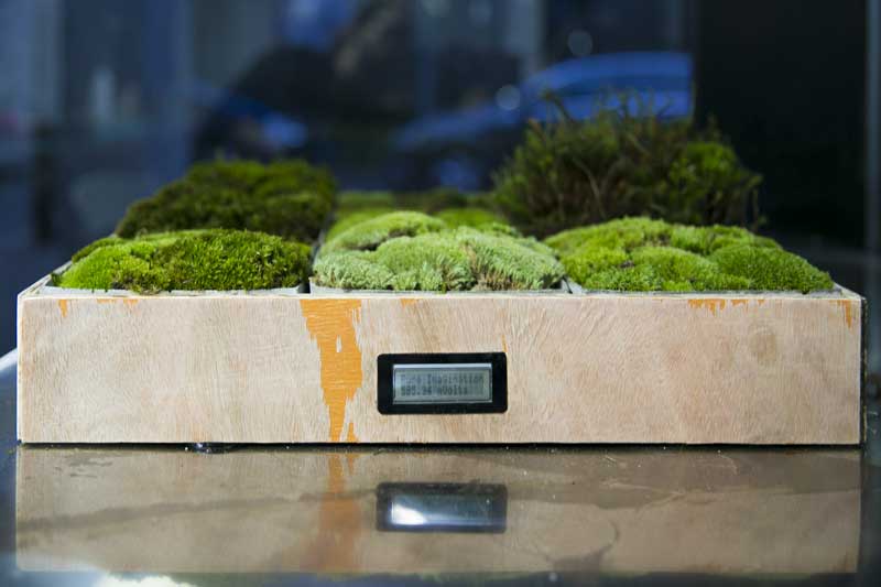
I started with single unit testing modules. Then built a tabletop garden. Someday I will build an experience.

Following are some photos of the final assembly. Of note, this was just assembled prior to photographing, some modules were not even an hour old including one the module connected to the anode of the volt logging microcontroller. All 9 modules are linked in series.


The following are links to investigations done throughout the cycle directly related to the development of this final work.
Project files
Design, Materials and Methods
I would like to build a small moss (dominate) garden which has an electrical outlet of a contrasting color to green sitting on a small pole in the center. The electrical outlet is connected to a battery that is hidden in the base. The moss is organized in power modules which are connected and charging the battery. When something small is connected to the electrical outlet, the battery discharges electricity. The whole garden can be dissambled and reassembled with relative ease. A secondary objective is to make (most likely) independently powered monitoring equipment (lux, temperature, humidity, soil moisture, watt output) that records data to long-term memory.
I plan to continue to learn about plant driven bioelectrochemistry and develop this work into a full garden to be publicly exhibited to raise awareness to the spectacle that is plants juicing our refridgerators while rinsing our air. My aim is large, too big for the time limits of the Fab Academy. Therefore, I decided to scale down sharply (relative comment, even at a reduced scale, it will take monumental effort to achieve).
Update : After working into the project a bit, I decided to focus my efforts more on the data logging and monitoring aspects of the project as this will be more useful to developing the project post-Fab Academy. The sensational aspects: electrical outlet, battery charging, will not be completed for Fab Academy. While these may make it more intriguing as a consumer product or artwork, I have a long way to go to get to that point. Instead, I am now focused on developing this a research and development platform.
The molecular fuel cells will generate electricity that will be monitored by an Atmel controller driven PCB. Success will be evualated based on the robustness of the modules and the capability of the electronics.
Materials
- Bioelectrochemical grow module (9 units, 150mm x 150mm)
- Carbon Fiber (lab owned)
- Cotton, oil free, medical use
- Refined sugar (Starbucks, free)
- Moss
- Wet-proof carbon fabric, Cetech W1S1005
- Nafion 5% DuPont D520
- 20% wt Pt/ C
- Rubber sheet ca. 2mm thickness
- Stainless steel mesh (small as possible)
- Stainless steel bolts, washers and nuts
- Alligator clip leads
- Concrete, sand, cure accellerator (lab owned)
- Silicone for making concrete mold (lab owned)
- Foam for making silicone mold (lab owned)
- ca. 4mm acrylic (lab owned)
- Frame
- Plywood (lab owned)
- Electronics
- Fab lab stock electrical components
Processes
- Project management and documentation
- Spiral development cycle and aggregative, modular design
- HTML, CSS, photo, video and written documentation (this page)
- Computer-aided design (parametric)
- Rhinoceros x Grasshopper modeled
- Computer-controlled cutting
- Laser cut washers
- Laser cut molds (or 3d milled, yet unconfirmed)
- Computer-controlled machining
- 2D milled frame
- Molding and casting
- Cast grow modules
- 3d milled form for mold (or laser cut, yet unconfirmed)
- Electronics design and production
- Custom Atmel controller based PCB
- Input devices
- Voltage out monitoring
- (Time dependent) Environmental sensors: UV, humidity/ temperature, soil moisture
- Output devices
- LCD Information readout
- Interface and Application Programming
- Data storage and visualization
Task list and scheduling (June 7 -10 traveling)
- 3D design and fabricate test modules (complete)
- Calculate assumed Wattage output and garden size (# of modules) (June 4)
- Parametric 3D design garden (complete)
- Source cathode materials (complete)
- Source moss (complete)
- Source battery and sensors (complete)
- Design electronics (complete)
- Prepare presentation slide draft and video template (complete)
- Prepare cathodes (complete)
- Mill and cast grow module molds (complete)
- Prepare anodes and fill grow modules (complete)
- Fabricate PCB (complete)
- Program data capture and visualization (complete)
- Connect modules to sensor and begin testing data capture (complete)
- Update presentation material for video conference (complete)
- Fabricate frame (complete)
- Present progress to colleagues (complete)
- Final assembly (complete)
- Continue to develop the biological and chemical components (beyond Fab Academy)
- Scale (beyond Fab Academy)
- Assemble in exhibition space (beyond Fab Academy)
Unknowns
- How to sense voltage output
- How to mix and cast concrete, what are the design tolerances?
- How to store long term data (ie, read/ write external flash storage)
- How to charge, discharge a battery and track that progress (time dependent)
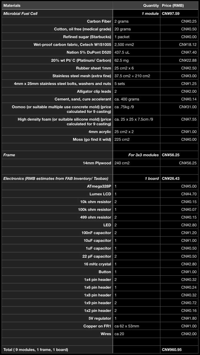
Price Breakdown
Following is a list of prices and quantities for the final build. Many of the materials, ie. acrylic, electronics were donated to the project from the fablab, others as part of the Fab Academy inventory/ session resources. For those materials, I checked online sources. The most expensive parts of the build are the chemical components and, shockingly, the silicone for the concrete mold. The silicone mold survives however, and that price would "decrease" with each successive cast. The bioelectrochemical system needs to be optimized for electricity output and material cost, perhaps alternative materials could be found for the cathode, which is where most of the money goes now.
Precedents
Most of the science I used comes from Dr. Paolo Bombelli's excellent research in the field of bioelectrochemical processes. This includes his published research: Electrical output of bryophyte microbial fuel cell systems is sufficient to power a radio or an environmental sensor and Biophotovoltaics: oxygenic photosynthetic organisms in the world of bioelectrochemical systems and Biophotovoltaics: Energy from Algae published in Catalyst Vol 21 #4, April 2011.
Alex Driver and Carlos Peralta's collaboration with Dr. Bombelli Moss Table. In a series of collaborations, they were able to run environmental sensors and a small LCD display for two weeks uninterrupted and operate a commercial radio for 80s after a day of charging a battery each using power generated solely from Moss based bioelectrochemical modules. This video shows an earlier work in which the table lamp shown is NOT powered by the [moss].
Elena Mitro's Moss Voltaics. Ms. Mitro generated electricity using moss and fabricated a modular system for containing the power cells.
Jakobe Skote's The Moss Powered Wifi-Jammer is a series of fabricated moss power cells which generate enough electricity to power wifi jammers. The work was conceived as a wearable.
Grow Module : The science
The nonvascular bryophyte microbial fuel cell operates in two main zones: anode and cathode. The anode side is a layer of moss, two mixtures of cotton and carbon (10:1, cotton : carbon weight) sandwiching a single layer of stainless steel mesh (as thin as possible). This anode mixture is from the 2016 October 3 Royal Society published work of Paolo Bombelli, et al. Electrical output of bryophyte microbial fuel cell systems is sufficient to power a radio or an environmental sensor.
The cathode is a sandwich of acrylic (bread), rubber (condiment), hydrogen electrode (10 wt % Pt/C + 5% Nafion solution + wet-proofed carbon cloth) and another stainless steel mesh. This cathode preparation is based on the work of Shaoan Cheng, et al. Power Densities Using Different Cathode Catalysts (Pt and CoTMPP) and Polymer Binders (Nafion and PTFE) in Single Chamber Microbial Fuel Cells published in Environmental Science and Technology, 2006 January.
The following illustration is from the previously linked Bombelli research report. It may not be cool according to copyright. Irregardless, I will replace it with one of my own soon. This is not my illustration but the general setup of a module is the same.

First I prepared the cathode. A catalyst is applied to the cathode and needs 24 hours in room temperature to cure.
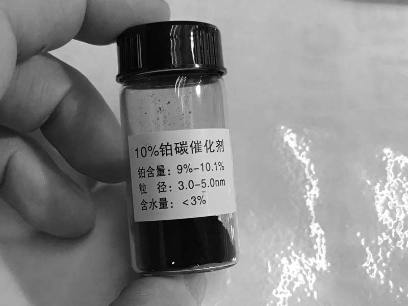
A commercial Pt catalyst (10 wt % Pt/C) was mixed with a chemical binder (5% Nafion solution) to form a paste (7 μL of binder per mg of Pt/C catalyst). The paste was applied to one side of the wet-proofed carbon cloth (CaTech, 0.41mm, W1S1005). The Pt content was approximated at 0.5mg cm-2.
| 100 square millimters wet-proofed carbon fabric | 0.5mg Pt 5mg 10 wt % Pt/C 2.5mg 20 wt % Pt/C |
35μL Nafion (10 wt % Pt/C) 17.5μL Nafion (20 wt % Pt/C) |
|---|
1g 10 wt % Pt/C

0.41mm Wet-proofed Carbon Fabric W1S1005

Small measuring tools. None of these materials are toxic but the platinum powder is precious and the carbon is messy. So I wear gloves.

I mix the Nafion with the Pt/C powder in this dish.
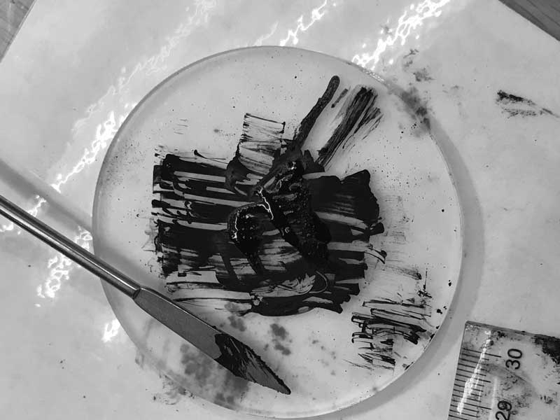
Then I scrape the resultant paste onto the fabric and set it aside for one day to bond the materials.

This is not me. The video is similar in process.
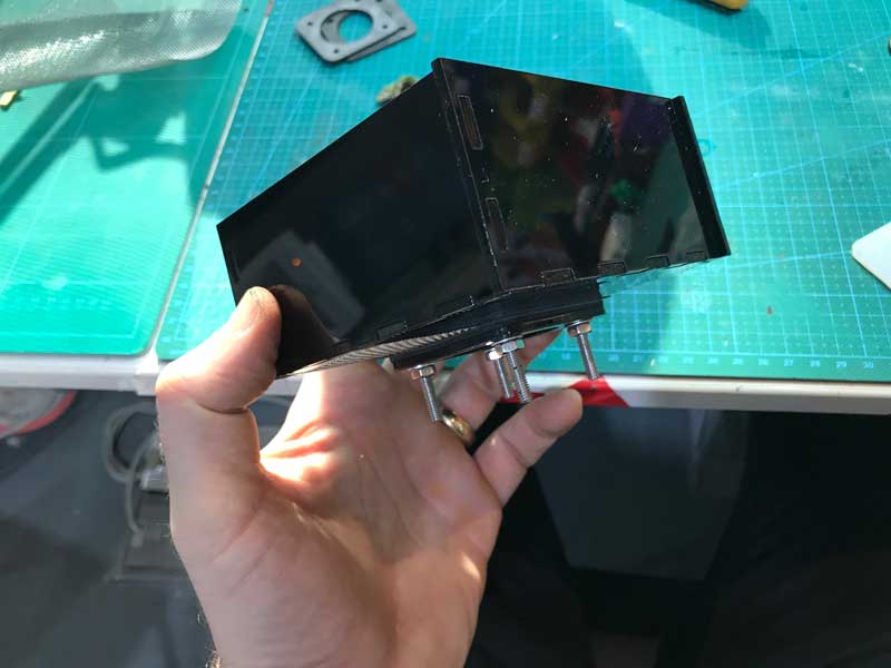
Flash forward one day. I sourced some rubber sheet material and cut that and acrylic for the custom components of the cathode side of the module.

And that assembled looks like this. The cathode connection will occur on the stainless steel. Be aware of the alignment of that with the anode of this module and others, depending on the module configuration.
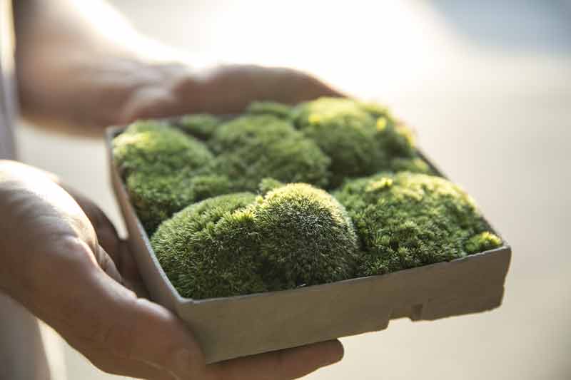
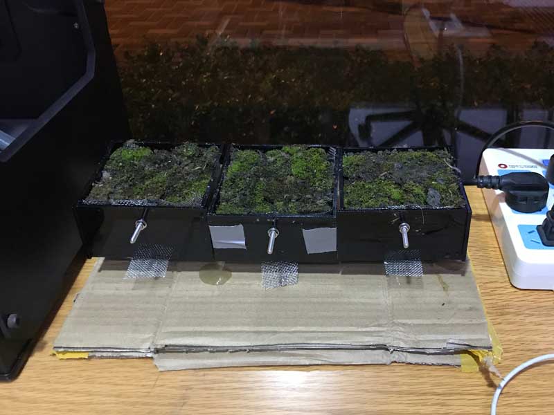
Three testing modules are ready for anode mixture and more moss.

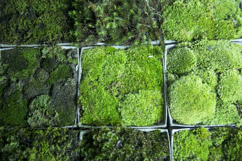
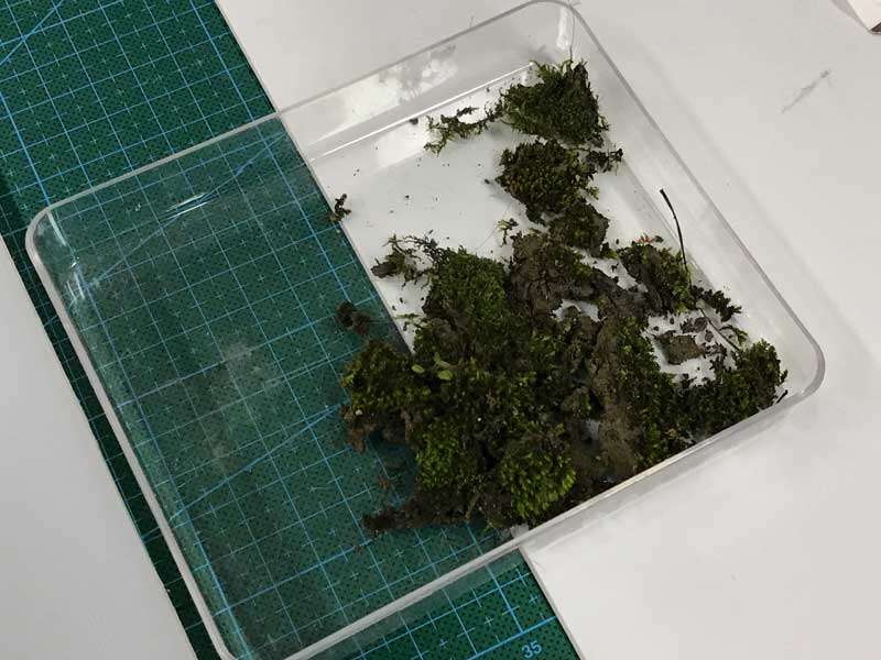
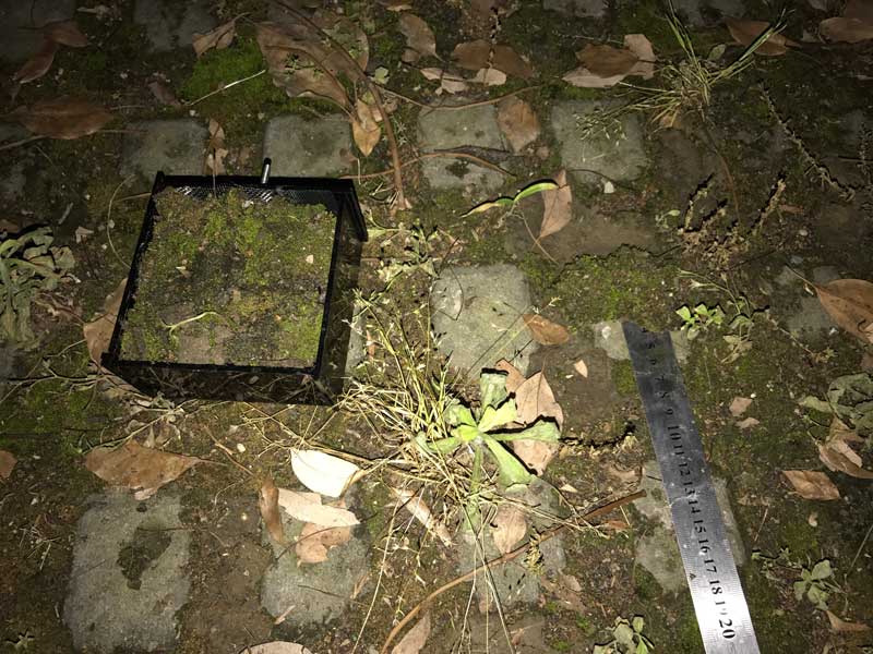
Just before I started preparing the anode, I locally sourced moss. For the final outcome, I may source a wider variety of moss from an online retailer in Shanghai.
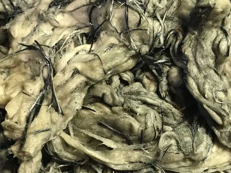
Now that I know where I will collect the moss. I am ready to prepare the anode mixture.
| 1000 cubic millimeters | This much cotton by weight | 1/10th of that weight in carbon fiber. |
|---|
Cotton

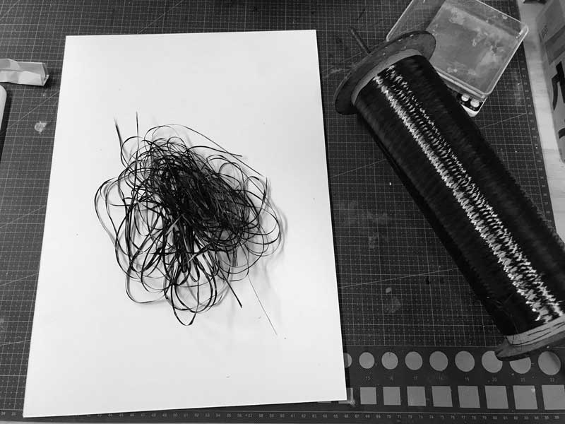
Carbon fiber. When cut into small pieces, this material is dangerous for your skin, eyes, lungs, everything. Cover all your skin, mouth and eyes. Do not be careless.
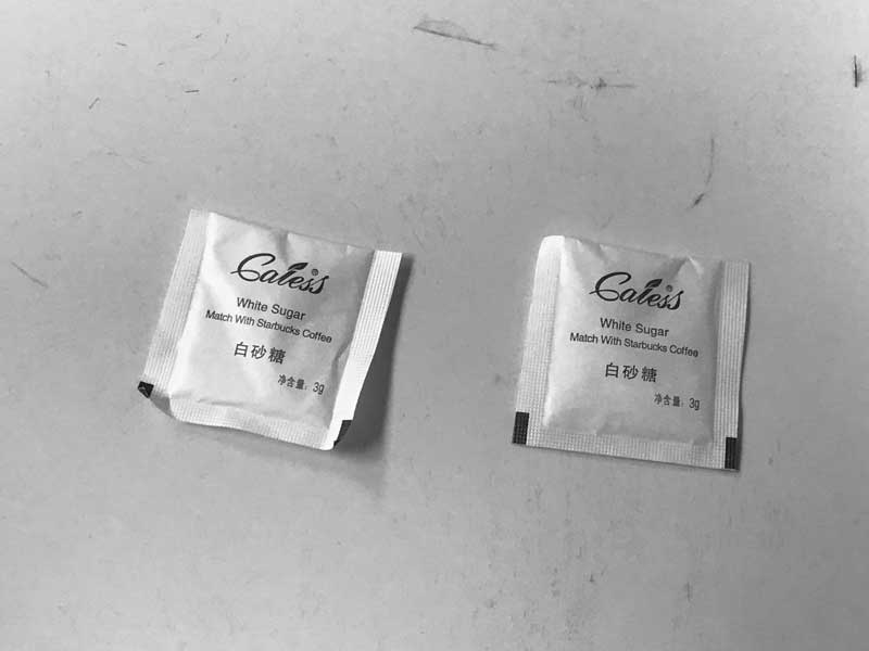
Starbucks sugar
Moss
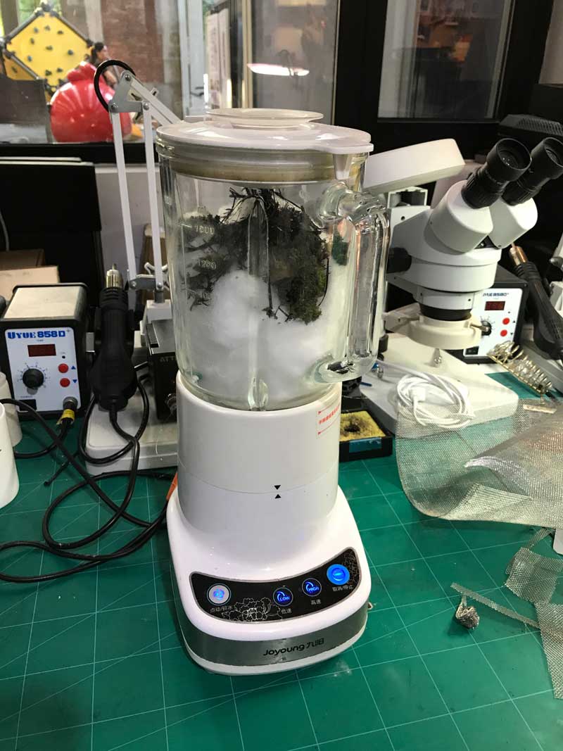
Combine all these with some water. I used a blender which was not great for the cotton. In the following iterations, I will likely pull the cotton apart by and and toss the materials together by hand.
Lay some tissue, preferably cotton tissue, on the bottom of the module.

Fill halfway with the anode mixture. On top of this, lay a layer of stainless steel mesh. I forgot to take a photo of this part.
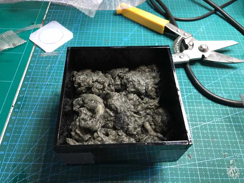
Fill nearly to the top with more anode mixture.
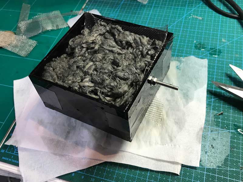
Finally, transplant moss. Be gentle. And water generously.
Three testing modules that I hope will soon begin outputing electricity.
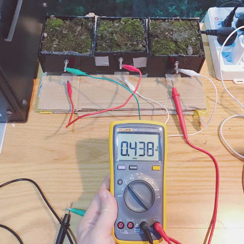
The next day, the modules were already outputting electricity. On the second day, when I returned to the lab the modules connected in series were outputting 438mV at 30uA and I am psyched.
Grow Module : Design and fabrication
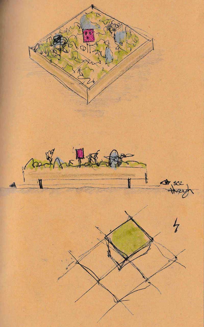
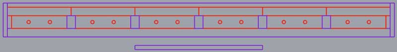
My idea is to first create a small modular testing garden. I began with some sketches on paper and Rhinoceros. The bioelectrochemical modules are red and the frame is purple. I think this way will be able to be broken down and assembled easily and can be grown or reduced by adjusting the array. While the sketch shows a six by six array, I might reduce it to five by five.

The testing modules were essentially cubes. This module is has a smaller bottom half to create a lip for sitting on the structure. In the upper portion there is a small bolt which protrudes from the module for connecting the cathode. This bolt will occupy the space between the modules in the removed rows of beams. I will do more work on the purple structure later. I need to add legs and configure the electronics holder.
When I was satisfied with the sketches, I started programming in Grasshopper. I started with what I previously made for the testing modules. I have been learning quickly, so I spotted a number of inefficiencies in that version. I like this one better. I am sure it can be optimized further after I learn more.

As before, all the important variables and a few others are easily configurable throughout the code.

This shows four cathode bolt holes but there will just be one.
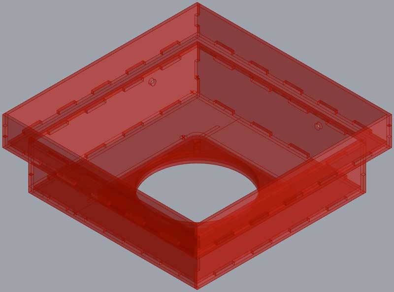
Then I can see a more detailed array of the modules.

And these are the pieces that need to be cut for one module. Each module is 150mm x 150mm which is larger than the testing modules, which were 100mm x 100mm. The green pieces are rubber, red acrylic.
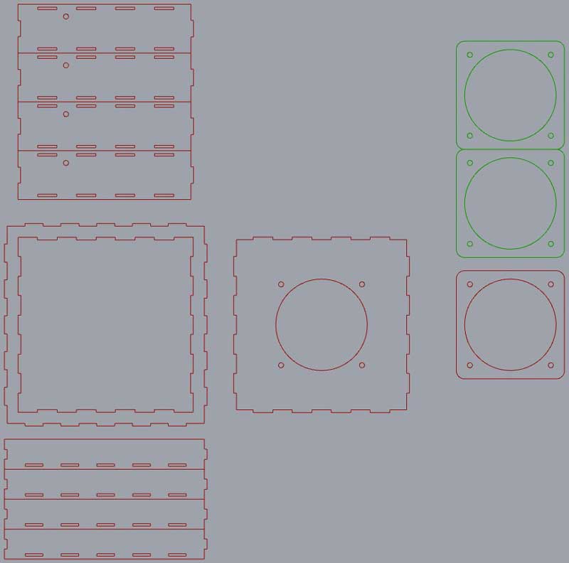
I roughly laid out the pieces of the modules so I would know how much acrylic I needed. I need 9 sheets at 660mm x 495mm if I want to cut 36 units. However, I may start with 25 which should be less than seven sheets of the same size.

Returning to this aspect of the work, I decided to do a laser kerf test on 2mm acrylic and cut a test box from the file I created a couple days ago.
Power : 100
Speed : 3
PPI : 1000
Laser kerf : 0.086
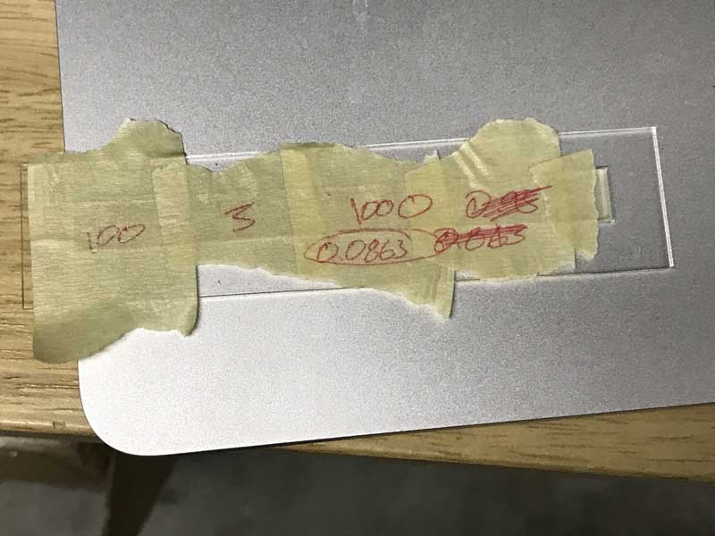
I put the acrylic on a thin layer of used wood, which gives some space for the smoke to exhaust from under the acrylic and effectively reduces the melting of the underside of the acrylic. By now, I feel like I have this parametric laser cutting process down.
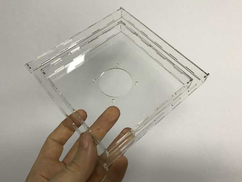
The quality is great, the press fit joints work well, and it sits on a beam structure as expected. Still, it does not fit right with me. While the laser cut method is very fast and low on fabrication effort, this container does not hold water well. I was thinking before fabricating this test, that I would go over all the joints with a sealant, or even a bonding agent. However, after seeing the test and watching Wednesday's review session, this solution does not seem nearly as robust or hands-free as is the conceit of the fab academy. I chose this solution thinking it would give me the best shot to finish the project for the presentation. Then what? I will have a flawed grow module.
With that in mind, I began considering how I may do the same basic module using a molding and casting method. While I do not have nearly the comfort level doing molding and casting projects as I do laser cutting, I do not see this being overly difficult. Once I have the mold, the casting should be a swift process of replication, depending on the material of course, which may be plaster, lightweight concrete, or a clear plastic, all swift curing. I will make that decision tomorrow if Saverio does not talk me out of this.
Moisture retention is critical in helping conduct electricity and providing a most enjoyable environment for the mold's friendly microbes. Casting the project would be highly replicable and solve the water retention issue of press fit joints. I hope to make a two part mold from oomoo with a wood frame for extra stability and alignment redundancy. If not two part, this may be modified to be 4 part or even 8 part with its symmetry. Our machineable wax is not large enough to do a 2 part mold, but could be melted into a larger piece.

After discussion, we decided that this mold could be done as a single piece, with more complicated milling. I have some milling multiple sides of stock in the past, so why not give it a try? Then casting the concrete will be streamlined.
I edited the 3D model for this new type of mold and used a previous flipping mechanism and found some discarded rigid foam outside. While cutting the first version, it shifted during the flip and I did not recognize it. Precious hours go to a tough lesson and I never knew until I flipped it after it was finished.

I redesigned the mold so that when it was flipped, it would slot precisely into a four sided jig. I modified the purple piece slightly after having cut that piece. This is why it does not match the proceeding photograph.


This time the opposite side milled perfectly. I milled an additional piece to hold the two pieces of foam in the correct relationship when casting the silicone mold.

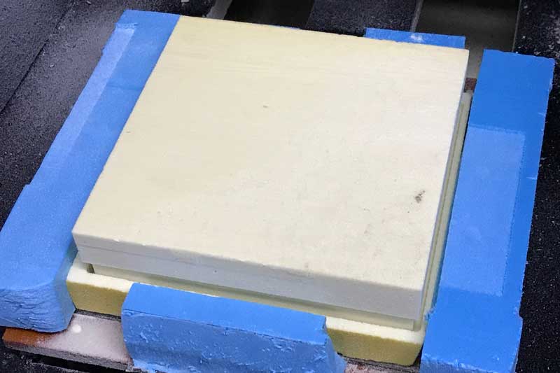
Aside from my careless positioning of the dogbone, the precision between the flips was remarkable the second time.

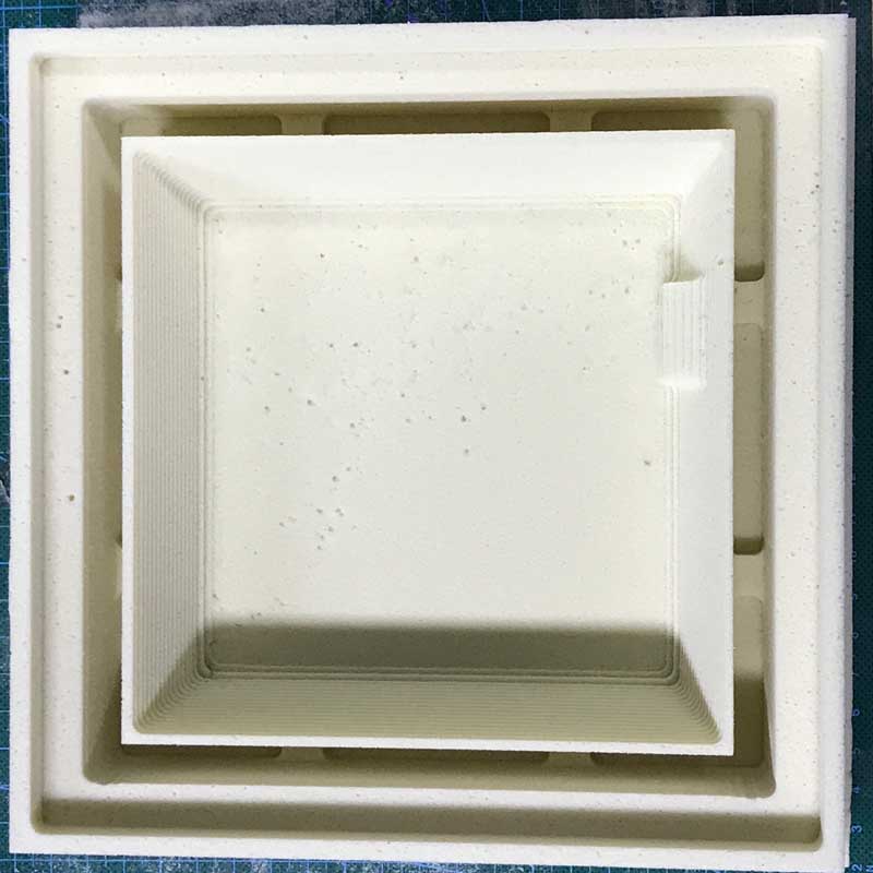
The oomoo was nearly depleted and I forgot to stir it thoroughly before mixing the two parts. It started to get rubbery in minutes while mixing and then was very hard to get into the form. Nonetheless: lockdown.
After carefully taking apart the mold, I found the silicone in decent shape considering some of the difficulty encountered in preparing it. I should have been more careful with double-checking the procedure for preparing Oomoo because it is expensive. Fortunately, this mold is still working well to do this day (post-build), and I have used it at least 20 times with cement thus far.

After cleaning up the mold, I cast my first concrete grow module. This is a quick curing cement. The first module, I used 300g of concrete mix and 150g of water with mold release sprayed on the silicone. Mixed thoroughly and it poured in beautifully.
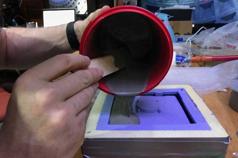
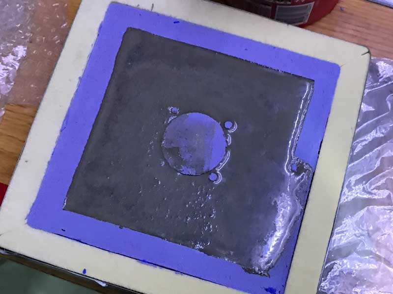
However perfecting the cement mix proved to be one of the more challenging aspects of this work. Currently, I am use a ratio of 3 : 1 : 0.1 : 0.5, cement : gravel : cure accellerant : water. Depending on environmental factors, the cast can be carefully pulled from the mold in 2 - 4 hours, then it will continue to harden significantly for the next couple of days and seemingly more so in the days that follow. After pulling the concrete, I followed effectively the same procedure to assemble the microbial fuel cell. Later I upgraded to a much finer stainless steel.
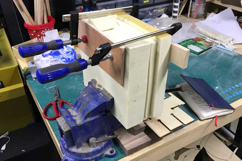
The frame is CNC milled from 14mm plywood. Low grade stuff found in the shop. The joists are limited to a single direction to clear space for wiring under the modules. For more information on the frame build, please refer to this post. Finally, a small pocket was cut for an LCD.

Takeaways : Changing to the concrete cells made the project more robust at the cost of a significant amount of time. I think laser cutting 9 cells would have taken two hours based on the experience of making one. Cutting the foam, waiting for the oomoo to cure, and casting the concrete (many many broken shells in finding the right formula) used easily over 100 hours to get 9 modules. When the cement is wet, water will slowly drip through the walls so it did not completely solve that issue with the laser cut modules. Granted, pouring cement is simple, when the formula is known. Further, the mold had issues beyond the oomoo averted disaster, there was significant flex which fortunately could be made up for in the frame. The walls are not straight. I do not mind it for this prototype because it has a nice quality but in demand of greater precision, I will have to reinforce the mold more and do better with the oomoo casting.
That said, I am happy I went through with the cement casting. I think finding these problems and working through them in a limited amount of time and budget to find a suitable solution is an important experience. Further, I certainly upgraded my technical capabilities with 3D, multi-sided milling, multi-part molds, and casting. Had a followed through with two hours of laser cutting, I doubt I would have learned anything new. Reflecting on my experience these past couple weeks with casting, that would have been a damn shame.
Download project files
Grow Monitors : What watches the watchers?
Simultaneous to the module development, I will produce some grow module monitoring equipment. Previously, I worked with a phototransistor sensor, an LCD output and wrote a basic graphical interface for live monitoring the phototransistor readings. Today, my goal is to combine these with voltage sensoring so I can begin tracking the correlation between sunlight and power generation in the bioelectrochemical testing modules.
Starting with a little research, I found that by simply connecting an input voltage to an open ADC pin, I could take voltage readings. Duh. I have been doing this for weeks via the phototransistor.
I returned to the LCD PCB I fabricated for an ATtiny 44 with an LED. The LED was connected to ADC7 of the ATtiny 44. Great news because I can quickly modify this board for testing voltage.
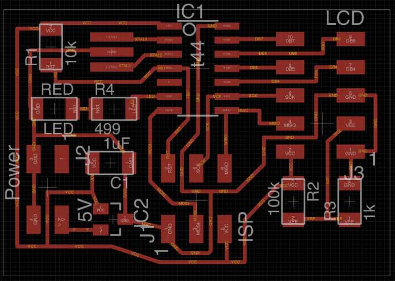
I never soldered the LED to the board. Instead, I soldered female pins, which is quite convenient now. I replaced the 499 resistor with a 0 ohm resistor at the electronics bench.

Then within Arduino IDE, I wrote this program. The floating number is necessary to get more precise readings, particularly with the small voltages coming from my current plant testing modules.
/*
  J.travis russett presents
  a simple programme to read up to 5 volts and print the results to an LCD
  with an ATTiny 44.


  The circuit:
   * LCD RS pin to digital pin 5
   * LCD Enable pin to digital pin 4
   * LCD DB4 pin to digital pin 3
   * LCD DB5 pin to digital pin 2
   * LCD DB6 pin to digital pin 1
   * LCD DB7 pin to digital pin 0

  lcd(RS, E, DB4, DB5, DB6, DB7)
 */

#include <LiquidCrystal.hx>

LiquidCrystal lcd(5, 4, 3, 2, 1, 0);

const int meterPin = 7;
int x;  //analogue pin reading
float y;  //converted to voltage

void setup() {
  //LCD stuff
   lcd.begin(16, 2);
   //Voltmeter stuff
   pinMode(meterPin, INPUT);
}

void loop() {
  int x = analogRead(meterPin); //Reads the analog value on pin A3 into x
  float y = (float)x * 5.000 / 1023.000; //convert analogue reading to Voltage
  lcd.clear();
  lcd.setCursor(0,0);
  lcd.print("Voltage: ");
  lcd.setCursor(0,1);
  lcd.print(y);
  delay(1000);  //one second delay between readings, keep a small delay to compensate serial comm
}
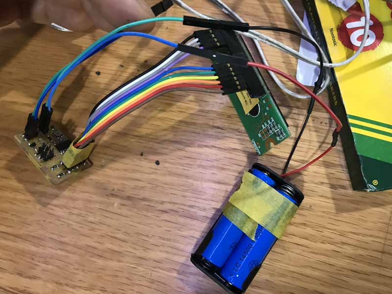
The cathode of the power source connects directly to the ATtiny pin and the ground is common to the board. I tested program with this pair of rechargeable batteries which may come into play at a later point to store energy produced by the plants.
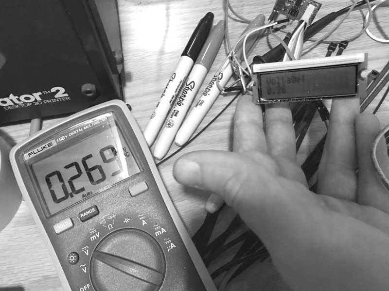
As my father loves to proclaim before a critical test, moment of truth. I connected the board to the plants (wired in series) and another volt meter as control. I like it.
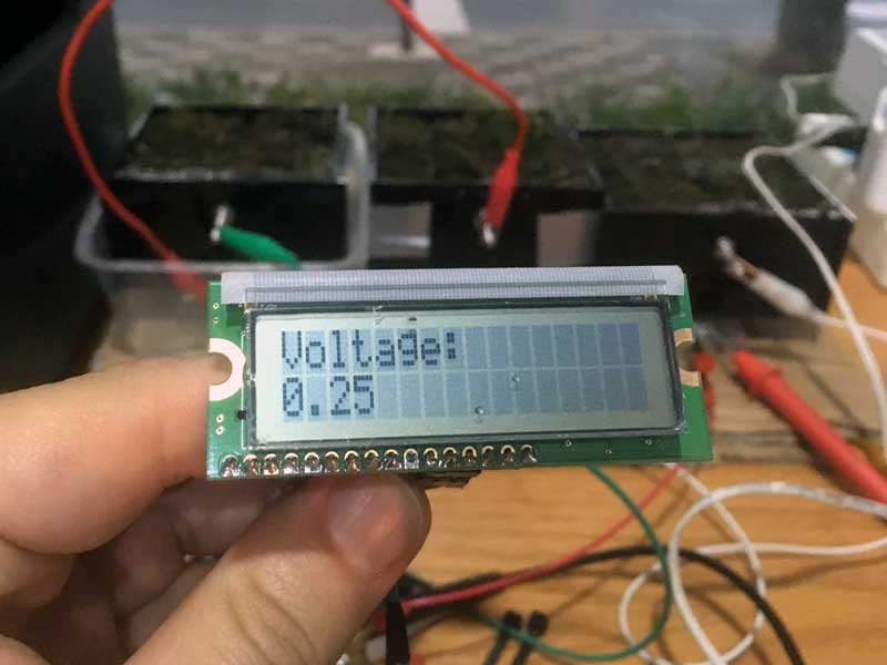
And a much clearer picture from Fablab maestro, Saverio Silli:
I started working on checking the controller's internal volt reference but when I decided I would like to evolve to the ATmega, I set it aside and have not had a chance to resume yet. Because the readings from the controller are relative to the voltage coming in, and voltage can vary slightly from source to source, this is a way to calibrate analogue readings. As usual, it is in the datasheets.
#include <LiquidCrystal.h>

LiquidCrystal lcd(5, 4, 3, 2, 1, 0);

const int meterPin = 7;
int x;  //analogue pin reading
//float Vcc;  // 1.1V ADC Reference Voltage comparator
float y;  //converted to voltage

/* This doesn't work on an ATtiny44 right now
long readVcc() {
  long result;  // Read 1.1V reference against AVcc
  ADMUX = _BV(REFS0) | _BV(MUX3) | _BV(MUX2) | _BV(MUX1);
  delay(2); // Wait for Vref to settle
  ADCSRA |= _BV(ADSC); // Convert
  while (bit_is_set(ADCSRA,ADSC));
  result = ADCL;
  result |= ADCH<<8;
  result = 1125300L / result; // Back-calculate AVcc in mV
  return result;
}
*/

void setup() {
  //LCD stuff
   lcd.begin(16, 2);
   //Voltmeter stuff
   pinMode(meterPin, INPUT);
}

void loop() {
  //Vcc = readVcc()/1000.00;
  int x = analogRead(meterPin); //Reads the analog value on pin A3 into x
  float y = (float)x * 5.00 / 1024.000 * 1000; //convert analogue reading to Voltage
  lcd.clear();
  lcd.setCursor(0,0);
  lcd.print("Pure Imagination");
  lcd.setCursor(0,1);
  lcd.print(float(y));
  lcd.setCursor(7,1);
  lcd.print("mVolts");
  delay(5000);  //one second delay between readings, keep a small delay to compensate serial comm
}
Next, I went to work on a way to visualize and permanently log data from sensors with Processing. Much more detail on this can be found in my previous post on applications. First the Arduino code.
#include <SoftwareSerial.h>
SoftwareSerial mySerial = SoftwareSerial (0,1);    // RX PA1 12, TX PA0 13

const int meterPin = 7;
int x;  //analogue pin reading
//float Vcc;  // 1.1V ADC Reference Voltage comparator
float y;  //converted to voltage
int a;
int b = 0;

/*
long readVcc() {
  long result;  // Read 1.1V reference against AVcc
  ADMUX = _BV(REFS0) | _BV(MUX3) | _BV(MUX2) | _BV(MUX1);
  delay(2); // Wait for Vref to settle
  ADCSRA |= _BV(ADSC); // Convert
  while (bit_is_set(ADCSRA,ADSC));
  result = ADCL;
  result |= ADCH<<8;
  result = 1125300L / result; // Back-calculate AVcc in mV
  return result;
}
*/

void setup() {
  //LCD stuff
   //lcd.begin(16, 2);
   //Voltmeter stuff
   pinMode(meterPin, INPUT);
   //Serial stuff
   mySerial.begin(9600);
   establishContact();  // send a byte to establish contact until receiver responds
}

void establishContact() { //establish connection with processing
  while (mySerial.available() <= 0) {
    mySerial.println("A");  //send A
    delay(300);   // adjust delay for stability
  }
}

void loop() {
  int a = mySerial.read();
  if (a == b) { // If data is available to read,
    //Vcc = readVcc()/1000.00;
    int x = analogRead(meterPin); //Reads the analog value on pin A3 into x
    float y = (float)x * 5.00 / 1024.000 * 1000; //convert analogue reading to Voltage
    //mySerial.print("mV = ");
    mySerial.println(y);  // print converted reading to Serial
  }
  else {
    delay(100);  //one second delay between readings, keep a small delay to compensate serial comm
  }
And the processing side is an evolution of my previous work. The biggest additions are corrections to the processing and arduino communication via serial, now Arduino properly awaits queries from processing, and Processing writes the data it receives with a time stamp to a text file in a format that can be simply copied and pasted into a spreadsheet application.
import processing.serial.*;

Serial myPort;   // create an object from Serial class
boolean firstContact = false;  //check if MCU is communicating
String val;      // data received from the serial port
float voltRead;      // converted string from serial port
color[] col = new color[1];
//int ax;
float xMax;    //tracking the highest value recorded
float xMin = 500;    //tracking the lowest value recorded
float xMinText;
float xMaxText;
PrintWriter output;

void setup() {
  size(700, 300);
  frameRate(40);
  myPort = new Serial(this, "/dev/cu.usbserial-A402YTB1", 9600); ///dev/cu.usbserial-FTH052EW
  initGraph();
  output = createWriter( "voltage.txt" );
}

void serialEvent( Serial myPort) {  //put the incoming data into a String -
  val = myPort.readStringUntil('\n');
  if (val != null) {  //make sure our data isn't empty before continuing
    val = trim(val);  //trim whitespace and formatting characters (like carriage return)
    println(val);
    if (firstContact == false) {
      if (val.equals("A")) {  //look for 'A' string to start the handshake
        myPort.clear();   //if it's there, clear the buffer, and send a request for data
        firstContact = true;
        myPort.write("A");
        println("contact");
        delay(100);
      }
    }  else { //if we've already established contact, keep getting and parsing data
      String [] numbers = split(val, ',');
      float sensor[] = float(numbers);
      //println(sensor[0]);  //use to check processing reading data correctly
      voltRead = (float)sensor[0];

      output.print(month());
      output.print(".");
      output.print(day());
      output.print("\t");
      output.print(hour());
      output.print(":");
      output.print(minute());
      output.print(":");
      output.print(second());
      output.print("\t");

      output.println( voltRead );
      myPort.write(1);
      println(1);
    }
  }
}

void draw() {
  //[mostly] static elements
  background(255);
  fill(0);
  rect(100,100,500,100);  // (a, b, c, d) (x-coord, y-coord, width, height) x &y are upper left corner
  textSize(16);
  textAlign(RIGHT);
  text("mV", 75, 158);

  //[mostly]dynamic elements
  //int ax = round(x);
  textAlign(LEFT);
  text(voltRead, 625, 158);
  fill(col[0]);
  if (voltRead > xMax) {
    xMax = voltRead;
  }
  if (1< voltRead && voltRead < xMin) {
    xMin = voltRead;
  }
  rect(100, 100, voltRead, 100);
  line(xMin+100, 75, xMin+100, 225);
  line(xMax+100, 75, xMax+100, 225);
  int xMaxText = round(xMax);
  int xMinText = round(xMin);
  fill(0);
  textSize(12);
  textAlign(CENTER);
  text ("min", xMin+100, 250);
  text (xMinText, xMin+100, 264);
  text ("max", xMax+100, 58);
  text (xMaxText, xMax+100, 44);
  delay(950);  //adjust for desired frequency of readings
  myPort.write(0);
  println(0);
  delay(50);  //adjust for serial lag
}

void initGraph() {
  col[0] = color(31, 255, 194);  // R, G, B values
}

void keyPressed() {
  output.flush();  // Writes the remaining data to the file
    output.close();  // Finishes the file
    exit();  // Stops the program
}
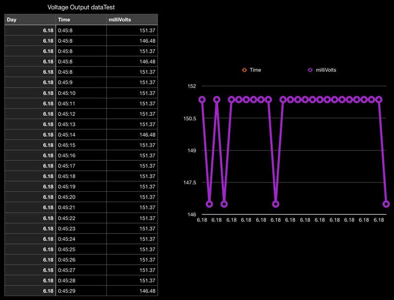
And this is a test outputting to a spreadsheet. This is macOS numbers, which uses tabs to differentiate cell data.
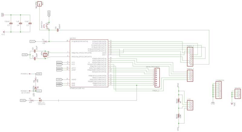
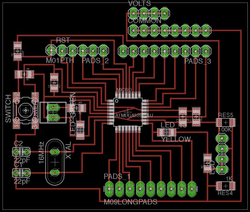
With some bits of code working and my ATtiny44 board maximized, I decided I would like a board that can output to serial and LCD, plus take readings from multiple module combinations or individuals and a variety of environmental sensors I found in the lab. That in mind, I thought I could upgrade to an ATmega board... for the first time in the Fab Academy cycle. Like many others, I started by studying then modifying Daniele Ingrassia's SatschaKit. I added many pins to be used for attaching breakout boards for environmental sensors and voltage readings plus resistors and additional pins for an LCD. After I fabricated it, I realized I should have added a regulator for voltage in from non-computer sources. I will do that and more in the next iteration.
In the meantime, I sourced an INA219 High-Side Current Monitor which work with I2C for current and voltage measurements. Plus I found this example uses Arduino IDE and ATMega I2C with an INA219 and an LCD output and by extension below, battery recharging management.
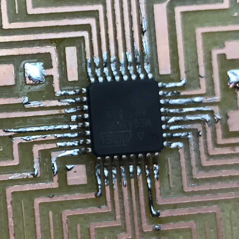
Soldering the ATmega is tough, especially if you do not have a sharp point on your soldering iron, like me. Instead, I applied small bits of solder to all the traces around the ATmega, carefully positioned it with the hot-air blower then slowly reflowed all the connections and added solder when needed. Jury is still out on whether that was effective, because I do not have the board running smoothly yet.
And the entire board stuffed:

The next step is to upload the Arduino bootloader for an Arduino Uno to the controller. This can be done with a programmer or even another Arduino. I used a programmer as per the SatschaKit github. I was having all kinds of problems with it though. First, I found the pads around the 16mHz resonator are small and were not making good contact. I did a bad job. The, I needed to update the Arduino Uno board manager. Next, I found fabISPs in the lab, mine and others', were having a tough time consistently uploading sketches. Sometimes the uploading process would simply stall.
After much consternation, I was able to get the bootloader then blink example uploaded to the board via a fabISP. However, I still am unable to upload sketches directly through an FTDI. I get a message about programmer not responding and then it tries again for 10 times. And, the fabISP is miss far more than make now for uploading.
Takeaways : And that brings me to now, a couple hours before the final blog updates for the session. I tried to spiral up to a more robust data logging controller but fell a little short. I will continue to debug this board design and fabrication until it works. I hope having more data helps me to optimize this particular setup of microbial fuel cell, share with other researchers, and develop more efficient systems of electricity generation. And, I do not like the wood frame at all. I will change that in the next iteration after the electronics are improved.
Download project files
I will post links to resources I have found helpful here.
Discussion
Michael Reynolds : Earthship Biotecture
Primavera de Filippi's Plantoid introduction.
History: Stuff I wrote previously
2017.2.1
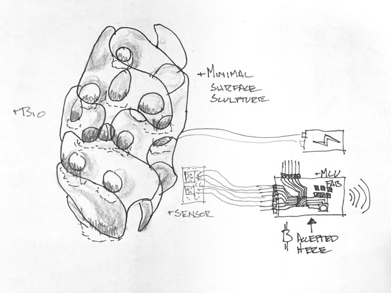
My ambition is to make an energy harvesting system using biological photovoltaics as an exhibition work to bring attention to clean, sensational possibilites for sourcing energy and the fact that we need [wildness] nature more than it needs humans. This system will be a network of modular components. Each module consists of a fabricated shell, preferrably from cradle-to-cradle capable materials, biological material (plant or algae, tbd), energy harvesting materials, bio-support materials. The network is connected to an energy storage and MCU. The MCU can be used for monitoring illuminance, humidity, temperature and volt output statistics to be used in optimization. Further, the energy harvested in the system may be used by the MCU to mine cryptocurrency, aka help build the block chain. It also will accept cryptocurrency donation so that it may spawn itself. While my design for the evergy harvesting and monitoring aspects of the system will be scaleable beyond what I produce for the academy, several modules will be fabricated into an eye-catching composition. I will update this page regularly as the project develops through 2017 June.
This first sketch is simply to illustrate the components and system. Many modules planters each with cathode and anode electrodes connected in series to a battery. The plants are charging the battery and also the battery can be discharged without disconnecting (wires) from the plant system.
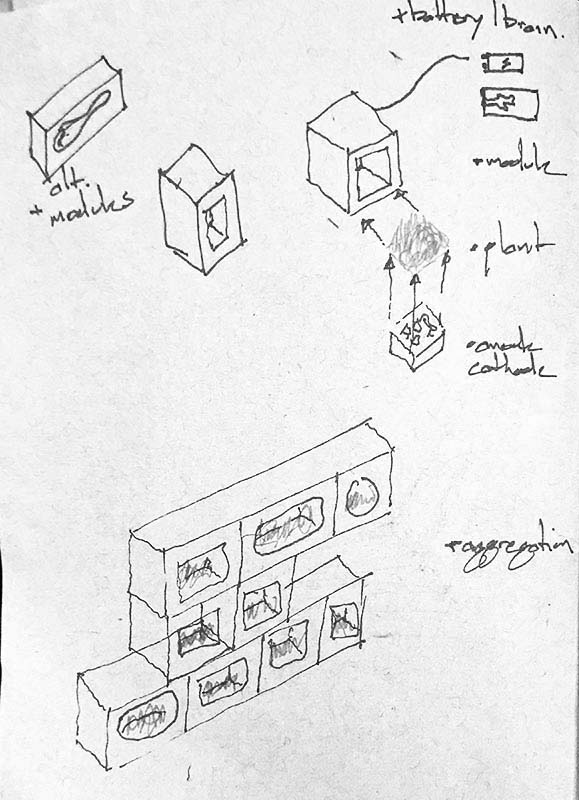
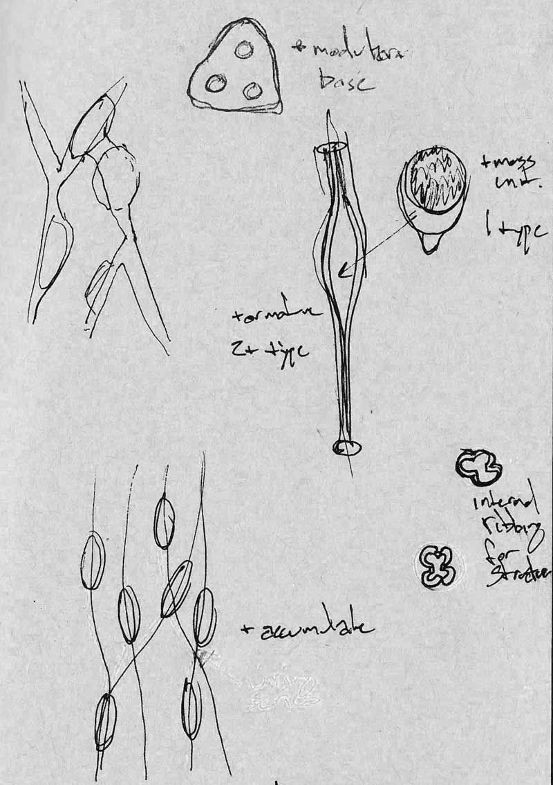
Update: use aggregative, modular minimal surface geometries as structural surfaces capable of self-supporting, shading, retaining moisture and containing plants. Constructed from repeatable milled or lasercut (folded) molds with clay or concrete casts.
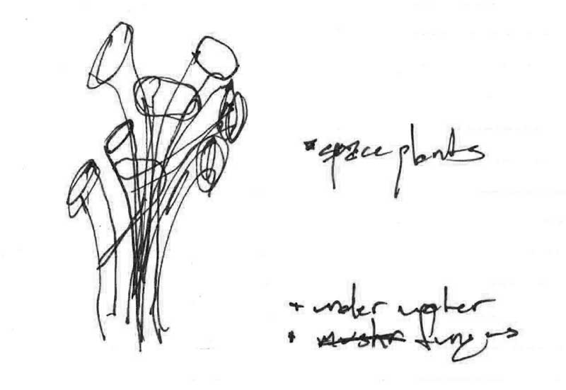
Update: make it look the part, alien. Repeatable deformed cones. Vertical infratructure would make the best use of space for this system of generating electricity (density).
Update: Considerations for how to utilize the energy harvested from the plants. In no particular order now.
- Random.org : Generate random numbers
- SETI@home : Communicate with aliens.
- Cryptocurrency : block-chain build slash accept donations.
Update: iterating on the vertical network idea. I think it would make an interesting project in terms of challenging fabrication, generative design, precision and connectivity. However, I am not convinced it is the best way to communicate my initial idea. Maybe this is something to revisit in the future.
Jump : Index
J.travis Russett © 2017
 All the work contained within is licensed under a Creative Commons Attribution-NonCommercial-ShareAlike 4.0 International (CC BY-NC-SA 4.0) License
You may remix, tweak, and build upon my work non-commercially, as long as you credit me and license your new creations under the identical terms.