~ Output Devices.
~ post date: 2017.4.3, recent update: 2017.4.6
"Of all the communities available to us there is not one I would want to devote myself to, except for the society of the true searchers, which has very few living members at any time."
Albert Einstein wrote that.
The history of liquid-crystal displays stretches all the back to the 1880s when Friedrich Reinitzer discovered liquid-crystals extracted from carrots. Carrots. What have you done lately? Today, LCDs are the quintessential communication interface between our computers and us. Understanding and interacting with the contents of an LCD is simple enough for us; how about on the otherside? How does a computer communicate to an LCD?
Project files
New PCB for LCD.
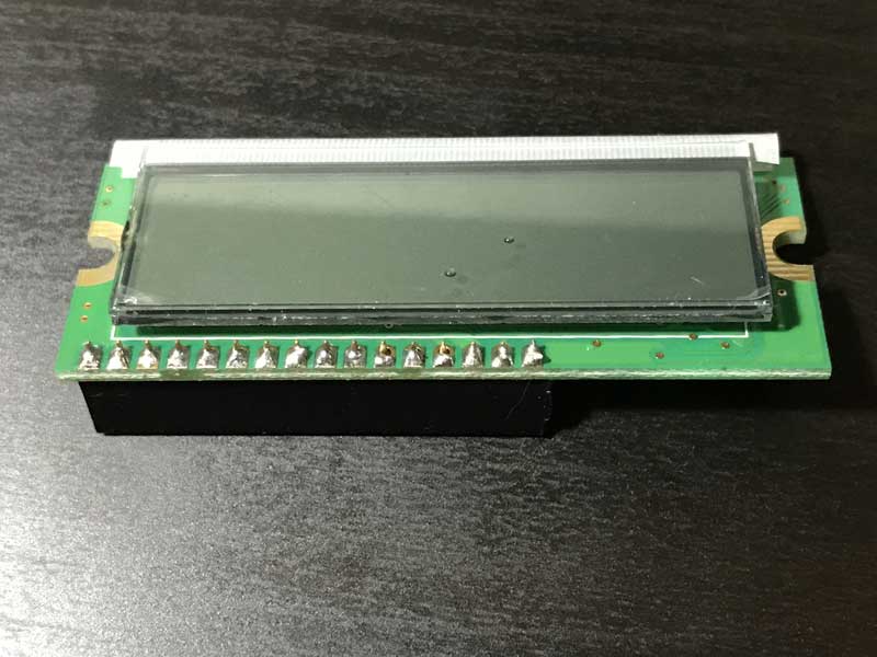
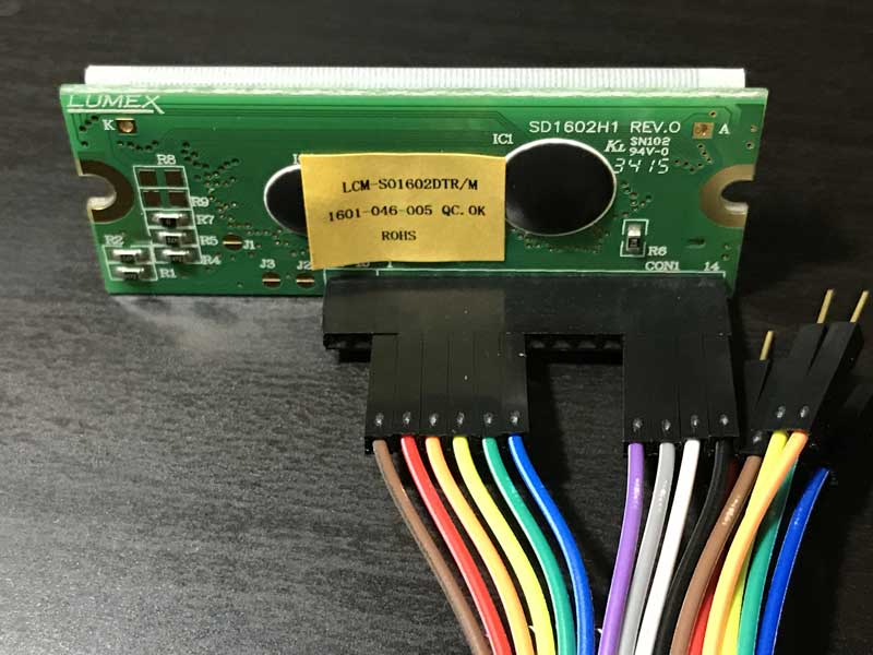
I am using a Lumex 16*2 character LCD Module. This LCD only requires 5v and six data pins to get up and running. I do not have a PCB with the free pins or proper configuration to use with this LCD. Not a problem however, because I have learned my way around designing, milling and stuffing PCBs. Get it.
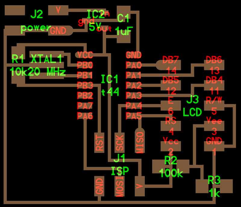
I started by inspecting Neil Gershenfeld's example LCD board. I posted a low resolution copy of the image here for convenient reference. The linked version is better. While following this is great for a beginner like me, I quickly became aware of other methods that I probably would have preferred to use. That is the point of the exercise and the liberation of literacy.
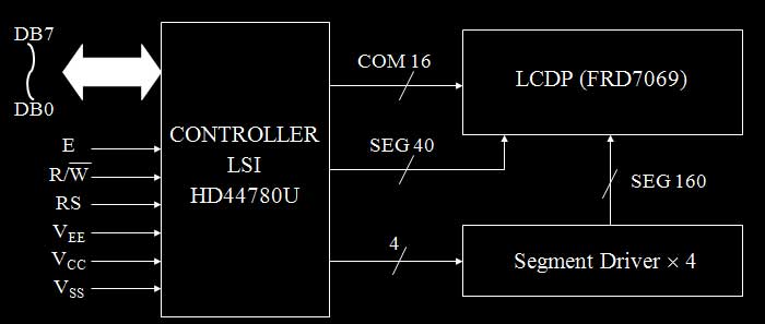
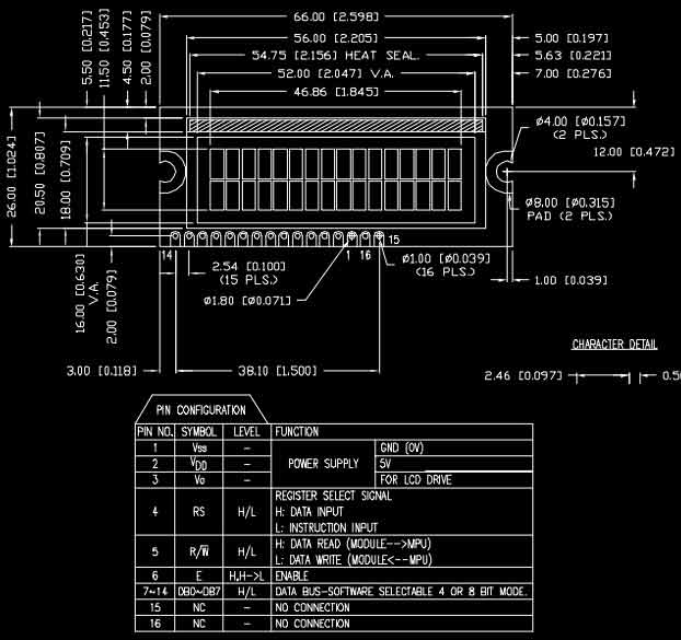
This LCD uses an Hitachi HD44780 LCD controller, and this is the block diagram. I will be using the LCD in 4-bit operation; therefore not connecting to data bus 0-3. You can count the input pins. Answer: ten.
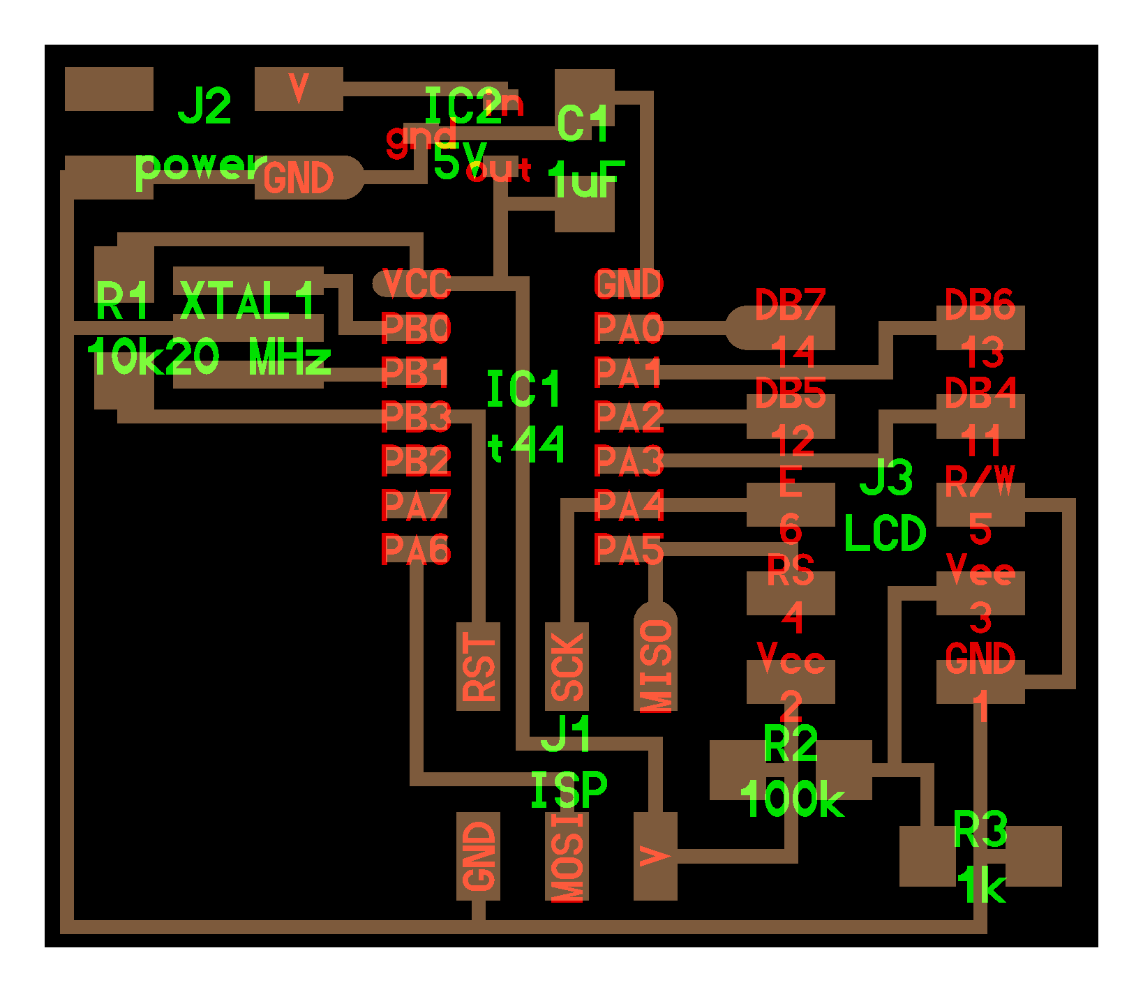
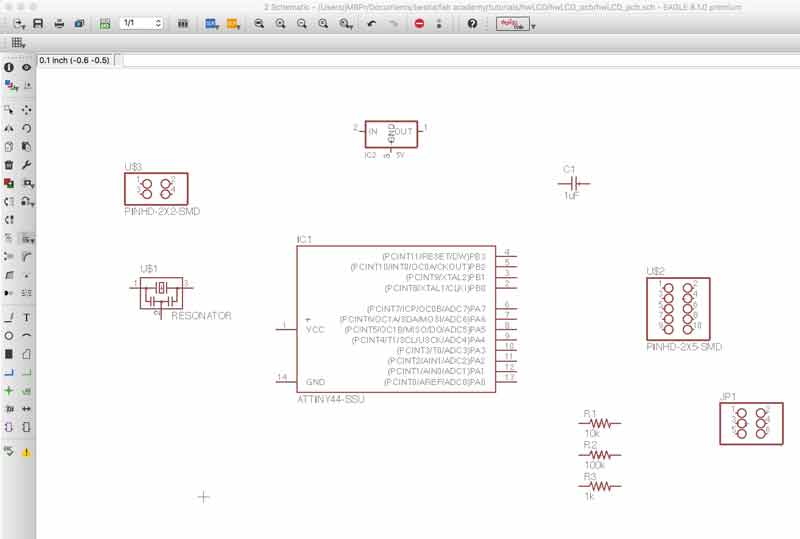
From his image I was able to develop a list of electronic components I would need to build my own board. In this schematic, there are two free pins on the ATtiny44, so I added an LED, for future fun. While building the list, I added the components from the Fablab common inventory Eagle library. You can just dump the contents into the schematic window and organize your efforts later.
- IC1 : 1x ATtiny44
- R1 : 1x 10kΩ resistor
- R2 : 1x 100kΩ resistor
- R3 : 1x 1kΩ resistor
- XTAL : 1x Panasonic ceramic resonator
- CAP1 : 1x 1UF capacitor
- ISP : 1x 2x3 pin header
- LCD : 1x 2x5 pin header
- Power : 2x2 pin header
- IC2 : 1x 5V regulator
- R4 : 1x 499Ω resistor
- LED : 1x red LED (directional)
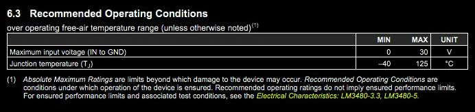
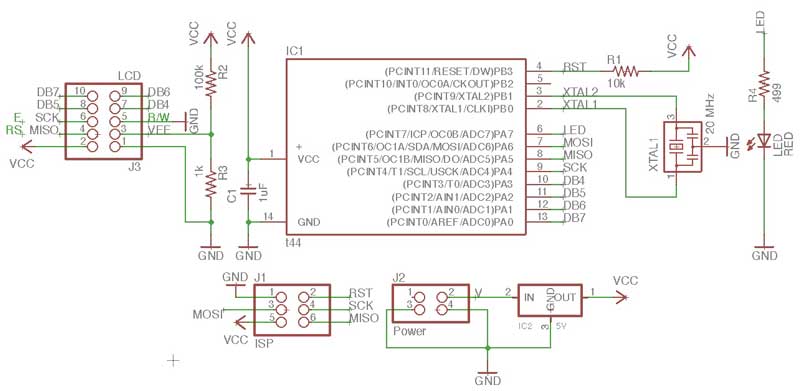
I duplicated my efforts from prior boards in terms of connecting the resonator to the ATtiny44, setting the ISP pins, capacitor, resistor on the reset pin and LED/ resistor combination. Then went about making connections to the 10 pin header for the LCD outputs. And finally, setup a regulator on a the power input. The LM3480 linear voltage has a maximium recommnded input of 30 volts. It will take what I give it and return 5 volts. Thank you.
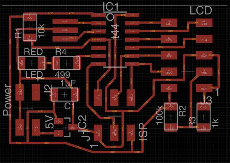
Develop the schematic to a nice level. It does not need to be complete because the board window communicates with the schematic graph. For instance, I completed a board layout with traces and after decided to add the LED.
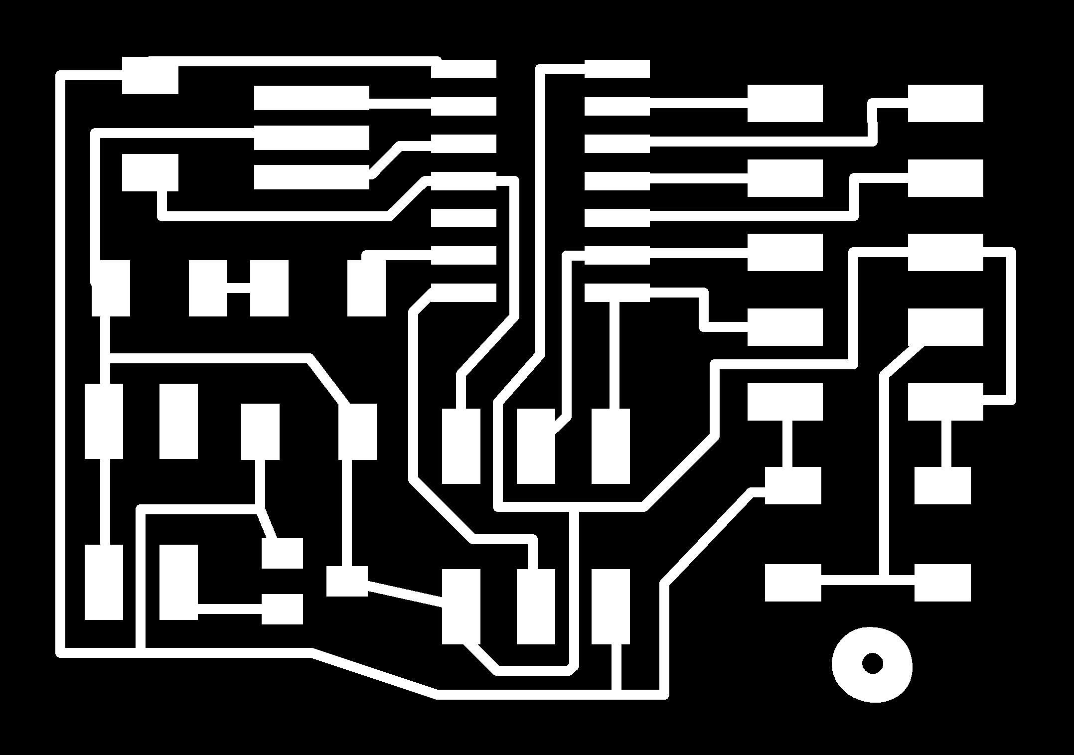
In the beginning, the PCB graph is a mess. Begin organizing your components on the board.
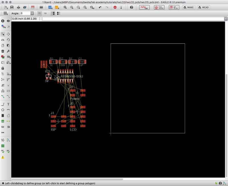
After roughly organizing the electronic compoonents on the PCB graph window, use Eagle's autorouter feature for some quick traces. If autorouter develops some 100% functioning layouts, you know you are on your way to the mill soon. This is my initial organization of the components and one of autorouter's trace layout.
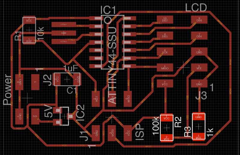
While the autorouter traces technically work, there were some inefficiencies that could be ironed out. For instance, the Mosi connection from the ISP to the MCU was odd. And, after getting the board organized, I saw a way I could squeeze in an LED. I could use the extra practice at the soldering table.
This time when I exported the PNG and opened in Photoshop for some small edits the size did not double. Other than using a new file, Eagle was recently updated. Perhaps one of those two changes effected the PNG coordination between the two applications.
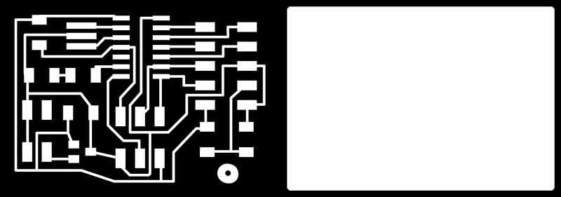
Again, the outline and trace files can be converted to tool paths in the Fab Modules. Double check all the settings before exporting the machine code.
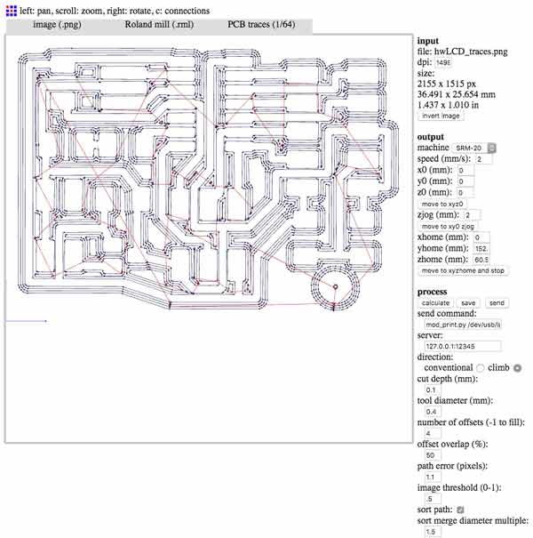
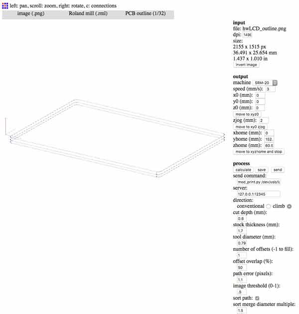
Tomorrow, I will mill the board, stuff it, and program this LCD. You can do that too. Download these files.
Download project files
I will post links to resources I have found helpful here.
Fabricating, wiring, learning
This dance is as follows: mill, solder, wire.
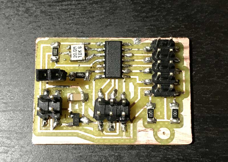
Familiar aesthetic for the board. Milling the traces at 0.10mm depth once again was unsuccessful so I dropped the depth to 0.15mm and milled on top of the previously milled stock. Soldering was significantly faster. This time, when heating the connections I kept a count in my head which varied from an one to three count according to the size of the components. Worked well in terms of pace. Checked all the connections with a multimeter. No problems. Initially I connected an incorrect resistor in front of the LED which took me a few minutes of failure to program communications with the LED to find. When I did, I pulled that fraud off the board and invited the right size in.
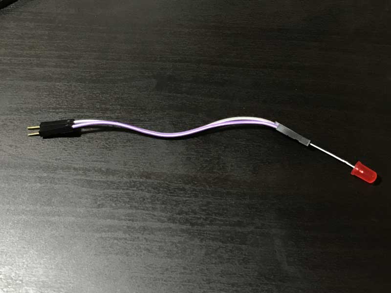
I soldered a 1*something female pin header to the LED. Easy connections.
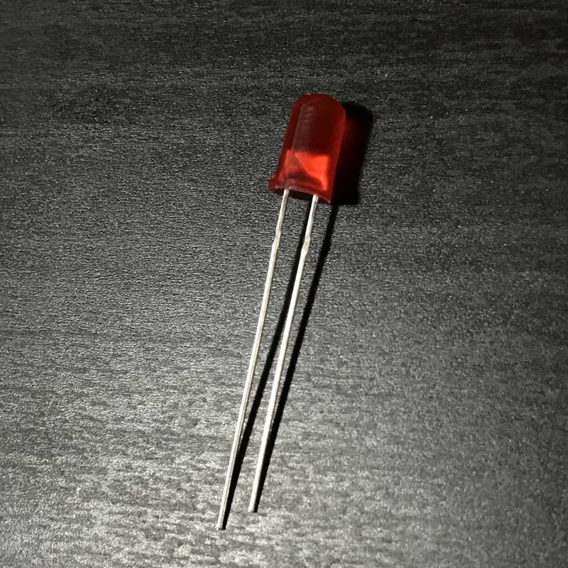
The shorter pin of the LED is the cathode side. Other signifiers: on the cathode side there often is a flat section of the rounded plastic base and the larger metal side inside.
LED extension cables.
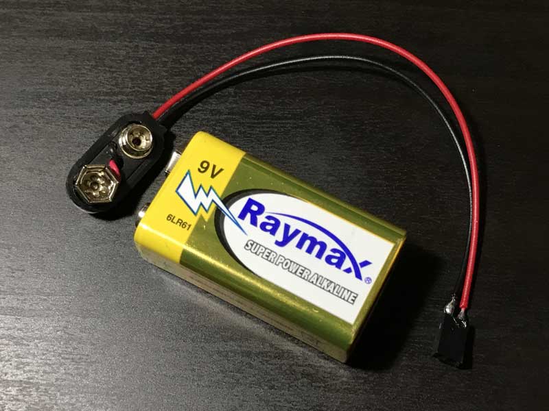
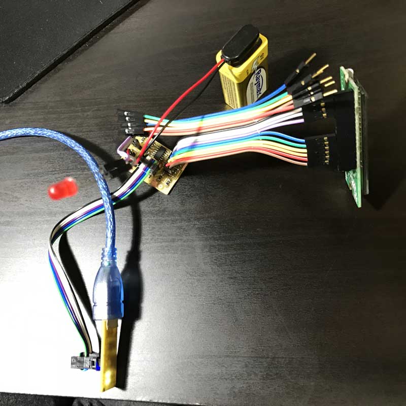
I am powering with this 9volt battery. This is a connection I soldered to a female pin header.
The wire connections to the LCD panel according to the datasheet.
And finally. with everything connected, it is time to program.
Download project files
I will post links to resources I have found helpful here.
Programming "Hello to the World" with C
I tested the effectiveness of my build with a C program written by Neil Gershenfeld.
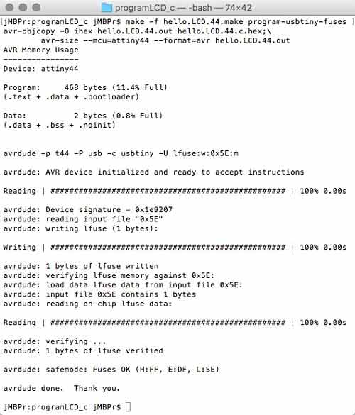
The contents of the make file are mostly the same as my previous ATtiny44 board. Because I used the same resonator, the timing fuses are the same. Only the name of the C accompaning C file has changed. Create the hex and out files.
make -f hello.LCD.44.make
Using my FabISP...
make -f hello.LCD.44.make program-usbtiny-fuses
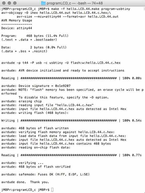
and then send the program...
make -f hello.LCD.44.make program-usbtiny
This feels good.
Download project files
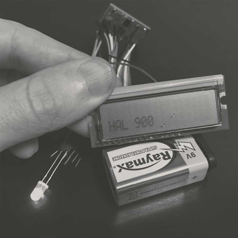
LCD cross Arduino
Arduino has a built in libary, "LiquidCrystal.h", for programming this type of LCD. I thought it would be fun to imagine a prototype of HAL 9000 prior to artificial intelligence using the LCD display to communicate and the LED to hint life.
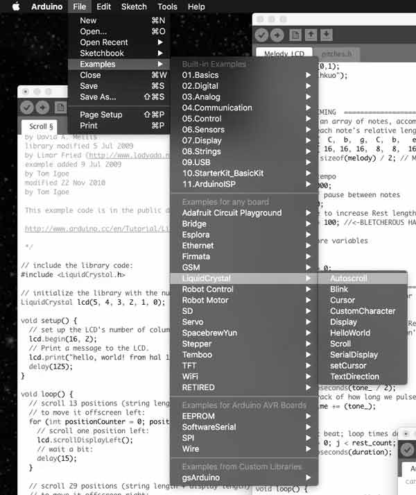
Arduino IDE is packaged with many sketches of LCD functions. Browse to File > Examples > LiquidCrystal and you can check those out.
First, write in the sketch the command to send the library for the LCD.
#include <LiquidCrystal.h>
Then, you need to dictate which MCU pins are connected to the RS, E, DB4-7 pins of the LCD (in that order). That information can be found by taking a look back at the board schematic and the ATtiny -> Arduino pinout diagram.
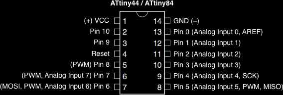
Write the code in the Arduino sketch as such, replacing the pin types with the pin numbers. The first box is the proper sequence, the second is the correct code for my board.
LiquidCrystal lcd(RS, E, DB4, DB5, DB6, DB7);
LiquidCrystal lcd(5, 4, 3, 2, 1, 0);
After examining and loading the examples to my board I made this modification of my breathing sketch and added some "dialogue" for HAL 900. I find that sending characters like this to the LCD, quickly exhausts the available programming memory. I think each character averages 1 byte of dynamic memory (maximum 256 bytes).
#include <LiquidCrystal.h>

LiquidCrystal lcd(5, 4, 3, 2, 1, 0);

const int ledPin = 7;
int ledLevel = 255;
int timer = 30;
int ledChange = 15;
int ledMax = 255;
int ledMin = 0;
int ledPace = 5;


void setup() {
  //LCD stuff
   lcd.begin(16, 2);
   lcd.setCursor(0,1);
   lcd.print("HAL 900");
   //LED stuff
  pinMode(ledPin, OUTPUT);
  ledMin = ledMax - (ledChange*(ledPace*2));
  ledLevel = ledMax - (ledChange*ledPace);
}

void heartOne() {
  while(ledLevel < ledMax) {
    ledLevel = ledLevel + ledChange;
    analogWrite(ledPin, ledLevel);
    delay(timer);
  }
  while(ledLevel > (ledMin + (ledChange*ledPace))) {
    ledLevel = ledLevel - ledChange;
    analogWrite(ledPin, ledLevel);
    delay(timer);
  }
}

void heartTwo() {
  while(ledLevel > ledMin) {
    ledLevel = ledLevel - ledChange;
    analogWrite(ledPin, ledLevel);
    delay(timer);
    }
  while(ledLevel < (ledMax - (ledChange*ledPace))) {
    ledLevel = ledLevel + ledChange;
    analogWrite(ledPin, ledLevel);
    delay(timer);
  }
}

void loop() {
  heartTwo();
  heartOne();

  lcd.clear();
  lcd.setCursor(0,0);
  lcd.print("/"I am putting");
  lcd.setCursor(0,1);
  lcd.print("myself to the...");

  heartTwo();

  lcd.clear();
  lcd.setCursor(0,0);
  lcd.print("fullest possible");
  lcd.setCursor(0,1);
  lcd.print("use, which is...");

  heartOne();

  lcd.clear();
  lcd.setCursor(0,0);
  lcd.print("all I think that");
  lcd.setCursor(0,1);
  lcd.print("any conscious...");

  heartTwo();

  lcd.clear();
  lcd.setCursor(0,0);
  lcd.print("entity can ever");
  lcd.setCursor(0,1);
  lcd.print("hope to do.\"");

  heartOne();

  lcd.clear();
  lcd.setCursor(0,1);
  lcd.print("HAL 900");
}
You can download your own copy of the sketch there.
Download project files
I will post links to resources I have found helpful here.
Jump : Index
J.travis Russett © 2017
 All the work contained within is licensed under a Creative Commons Attribution-NonCommercial-ShareAlike 4.0 International (CC BY-NC-SA 4.0) License
You may remix, tweak, and build upon my work non-commercially, as long as you credit me and license your new creations under the identical terms.