Second week Assigment
For this week, the assignments to be accomplish are:
- Drawing using 3D 2D softwares
- Draw using parametric design
- Using a 3D modeling software
- Use a new program
DRAW USING PARAMETRIC DESIGN
When Neil gave the example of the rivets on plane where has thousands of rivets, how do you change the design without to having to change each individual rive?
Welcome to the world of “Parametric Design”, so, instead of changing each rivet you parametric design them in advance so every time the design needs to be changed you can add constrains or variable to the size of the rivet and by changing those constrains, the change will propagate through the entire model.
In FabLab Seoul we make all our furniture but the most important part is that we try to recycle or use the left over, problem with that is the sometime is difficult to control the size that we will end up with, because every time we want to re create sometime we have to think how big is the piece of material to use and then start drawing.
To make a parametric design in Fusion360 we can help our selves by using two tools, parameters and constrains.
- Making some parametric constraints on Fusion360
clicking on the top menu Modify/Change Parameters, you bring out the "Parameter's" window
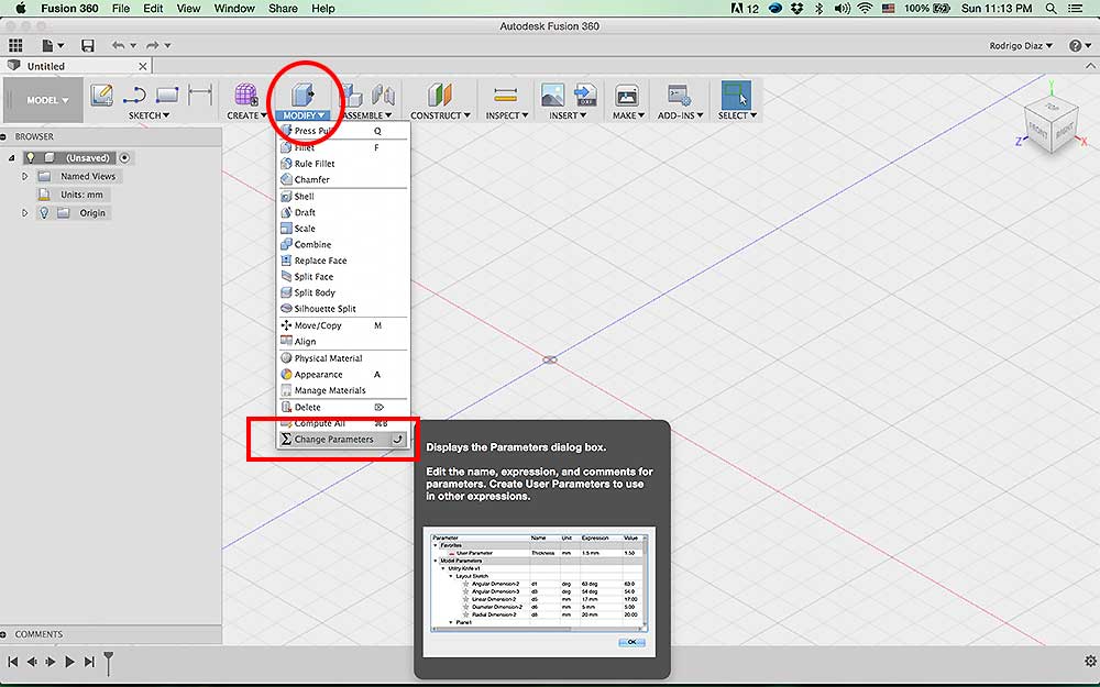
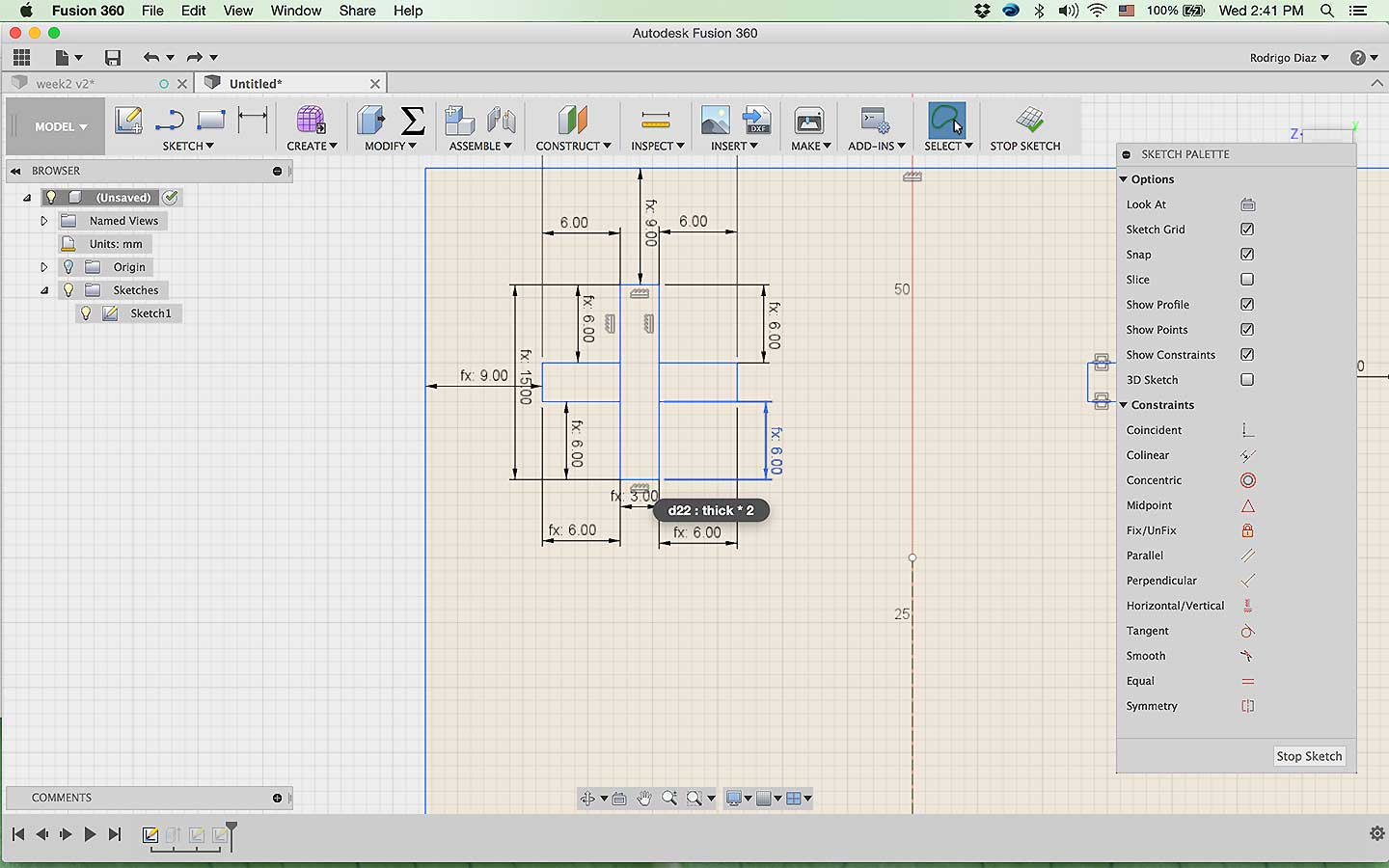
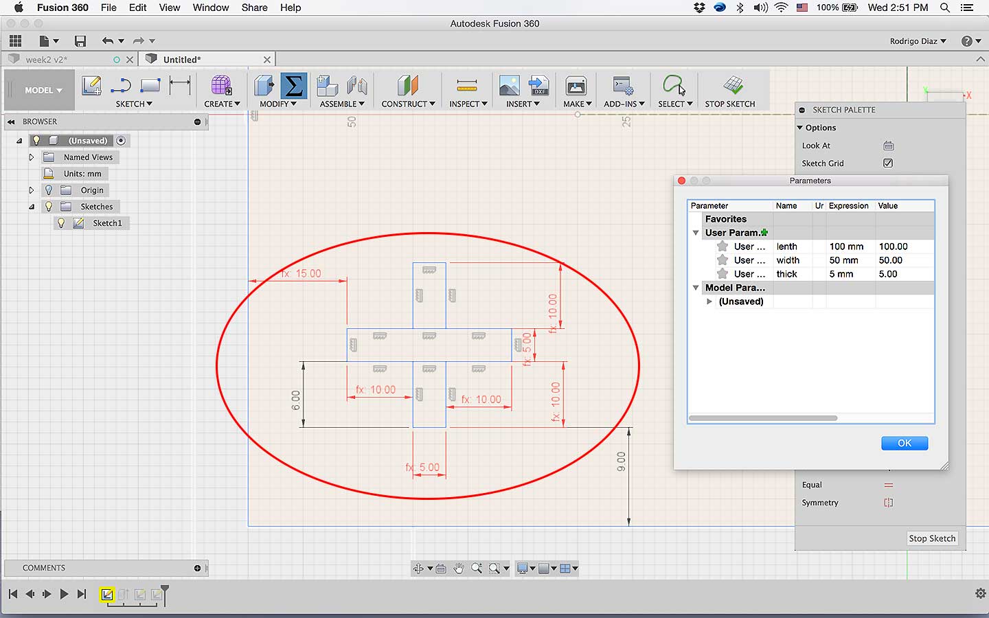
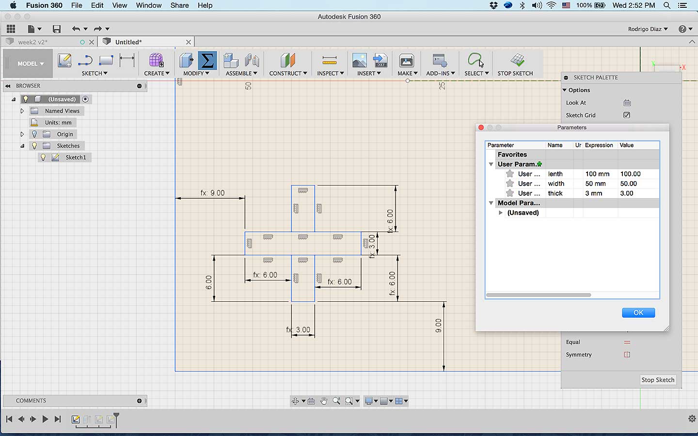
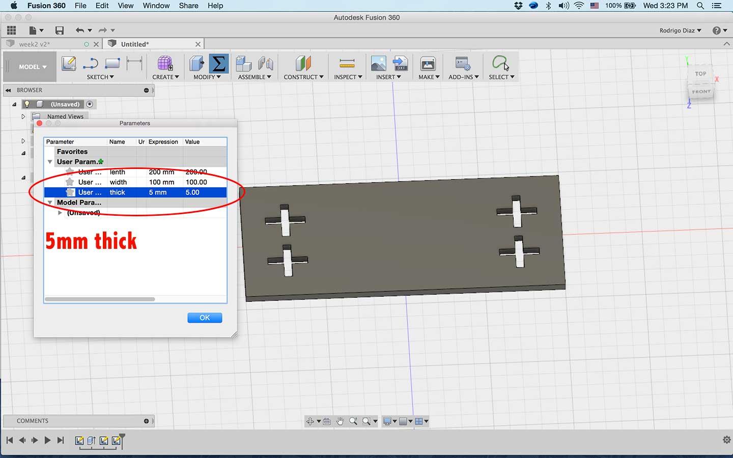
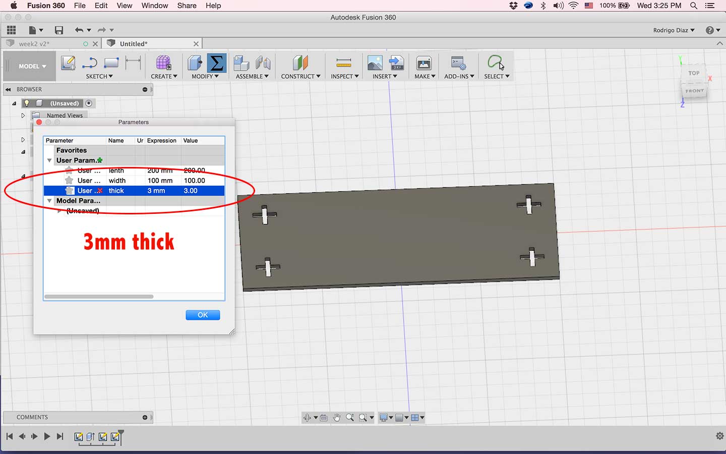
In the Parameter's window you can hold a variable number that can be call at any time to set a number, for example, "tichkness of the material", so when you start drawing any design and the thickness needs to be adjusted instead of changing 5mm thickness in each piece you can just name the material "thick" and that variable will contain the number on the parameters list meaning that when you change the list number for "thick" variable any lenth that has that number will be change. Here is a very useful link click for parametric design
- Creating Parameters
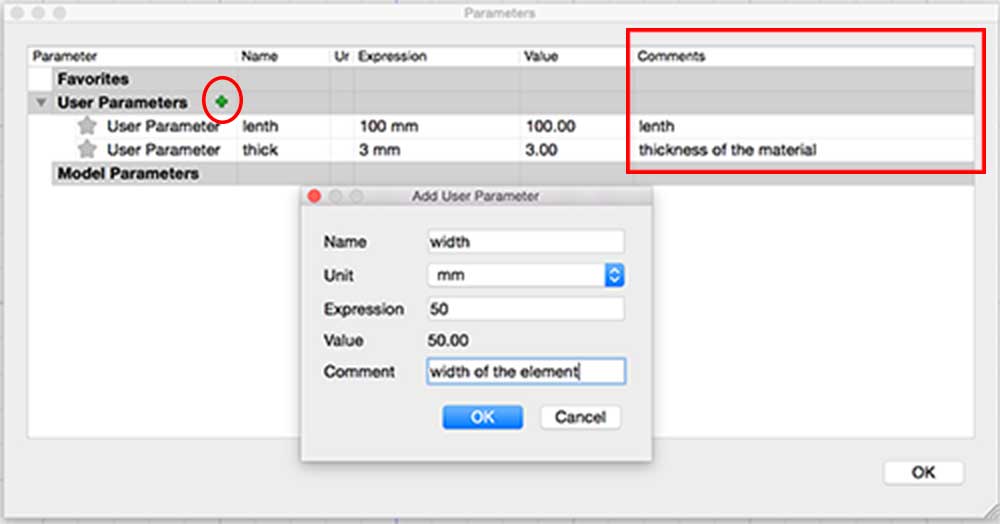
In order to add a parameters in to a variable just enter the information needed.
"Name" (name that will be called instead of a number),
"unit" (measurements units like inches, centimeters, mm, etc..),
"expression" (value, number designated to the variable), and lastly
"comment" (put something that will help you to remember this variable)
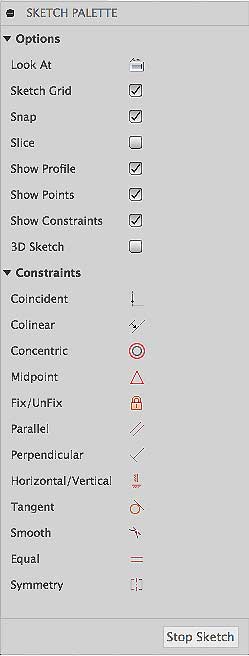
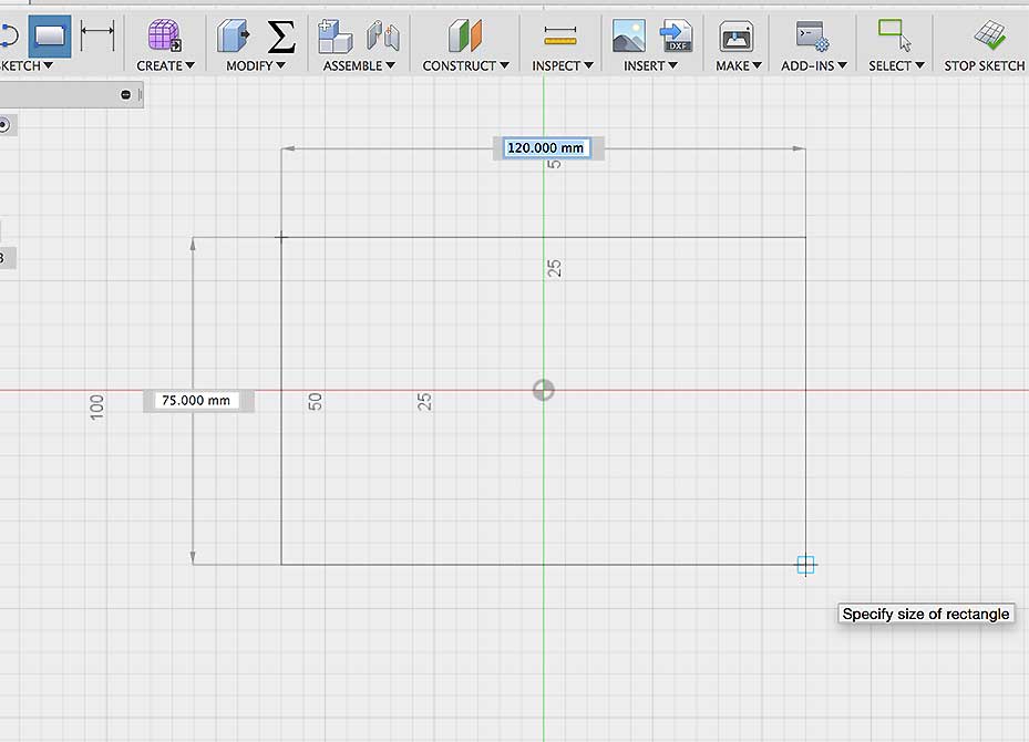
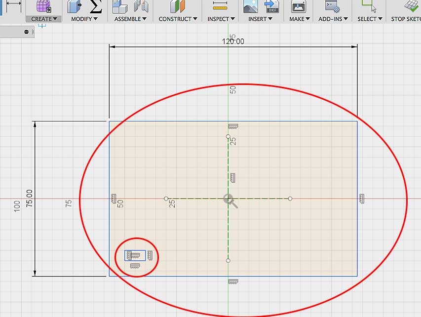
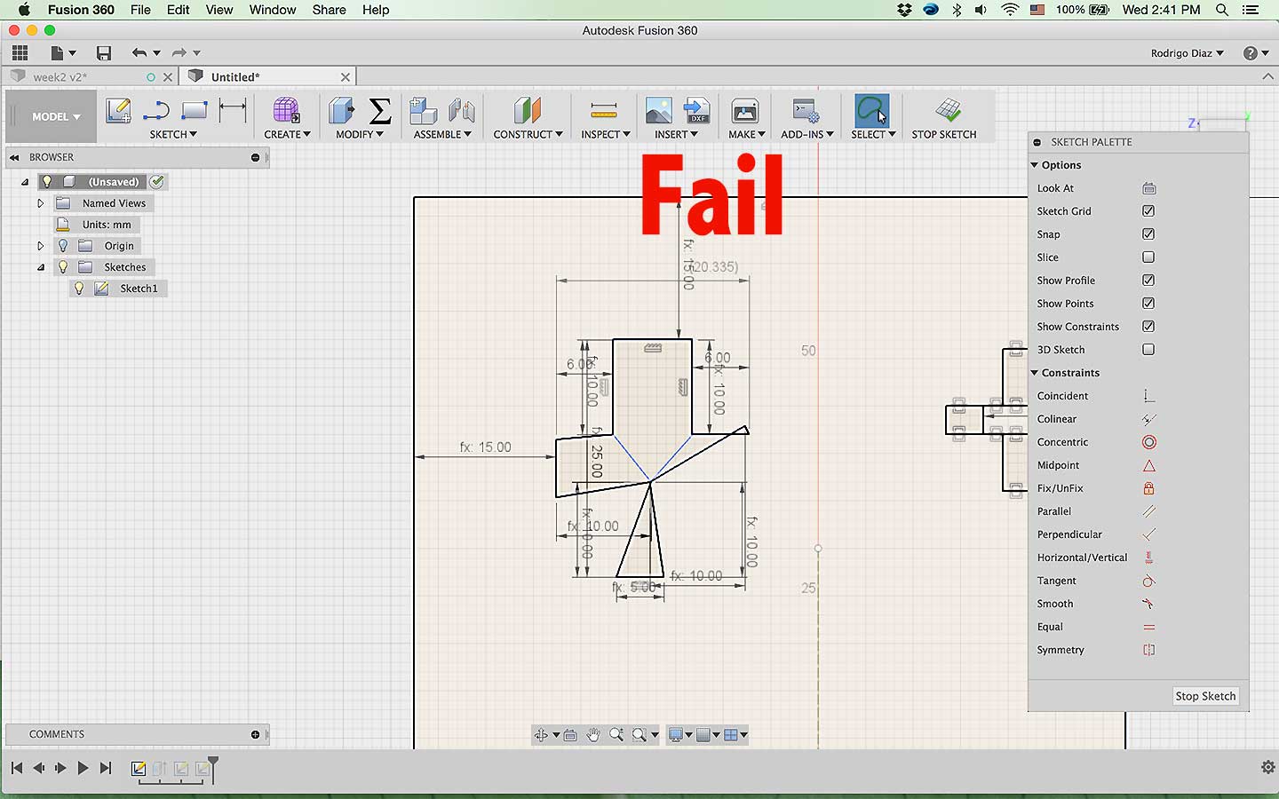
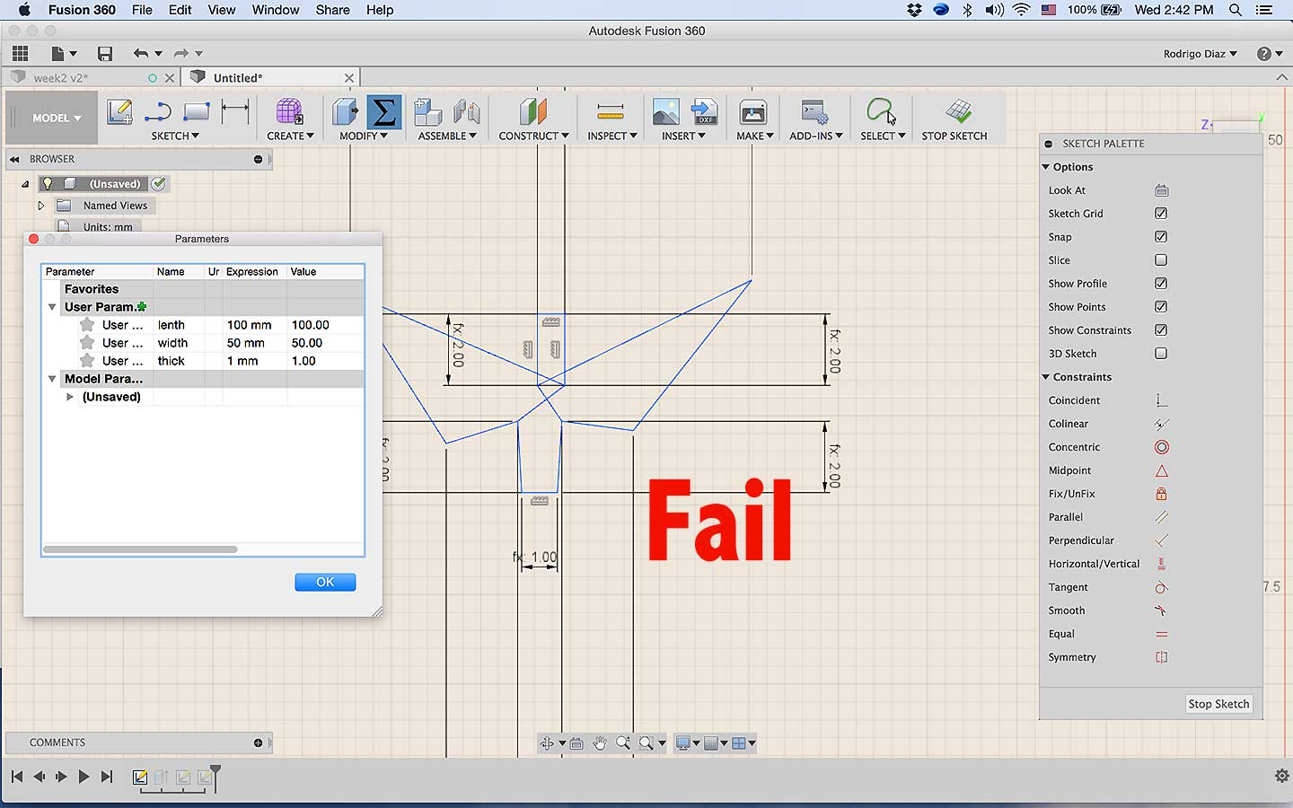
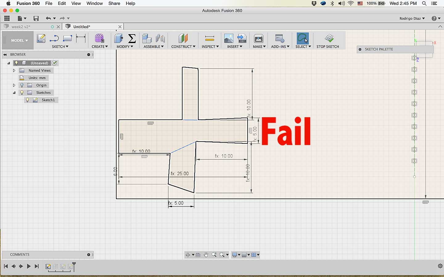
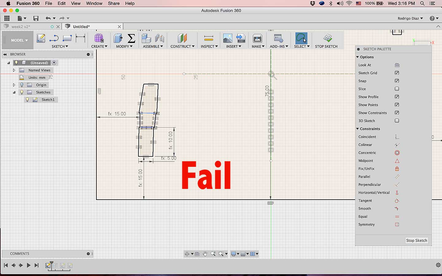
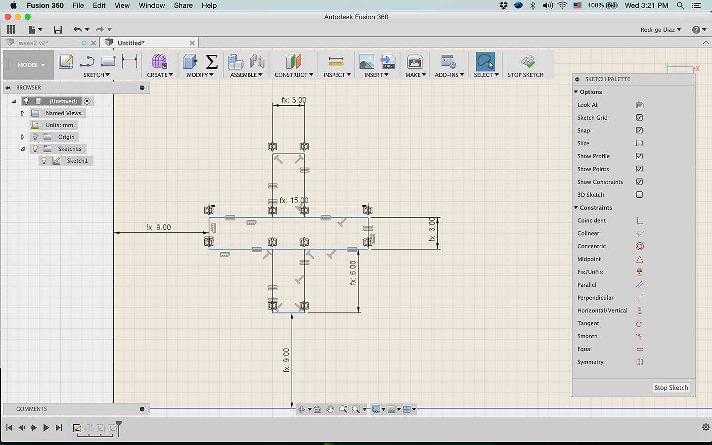
Another very helpful thing to learn is the constrain that you can set up while sketching so will maintain the desired shape even is you change the parameter's values this link can give you powerful understanding on how to apply constrains to create parameter design in Fusion360
- Creating Constrains
by using the constrain table and the parametric spread sheet, I staRted to draw.
I'm trying to create a joint part where the legs connet to the table. I already defined thickness = 3mm I my hope is that using parameters I will be able to change the thickness and the relation of the size will automatically adjust to constrainst
I create the relationship between the cross section and After I change the parameters for the thickness..... ㅠㅠ...ups doesnt work
More failures.... this is not funny... taking too much time
Failling again..
what I have not posted is that I already start from the beggining several times.....
I feeel like I'm an expert in crlt+z. Trying last time and then extruding!!
EUREKA!!!. when I change the thick parameters to 3mm/5mm the whole model adapt to it!!
Pros and Cons about Fusion360
- Not for begginers
- integrates 2D, 3D, rendering and CAM
- Powerful tools
- Big community behind the program
- Bright Future
USING A 3D MODELING SOFTWARE
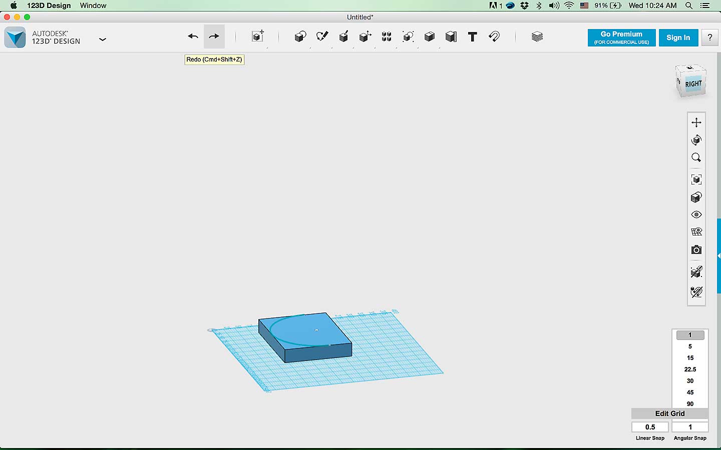
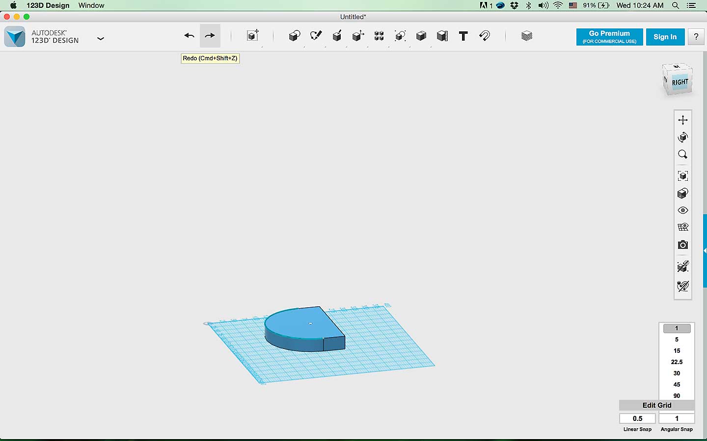
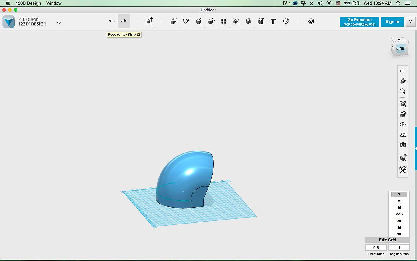
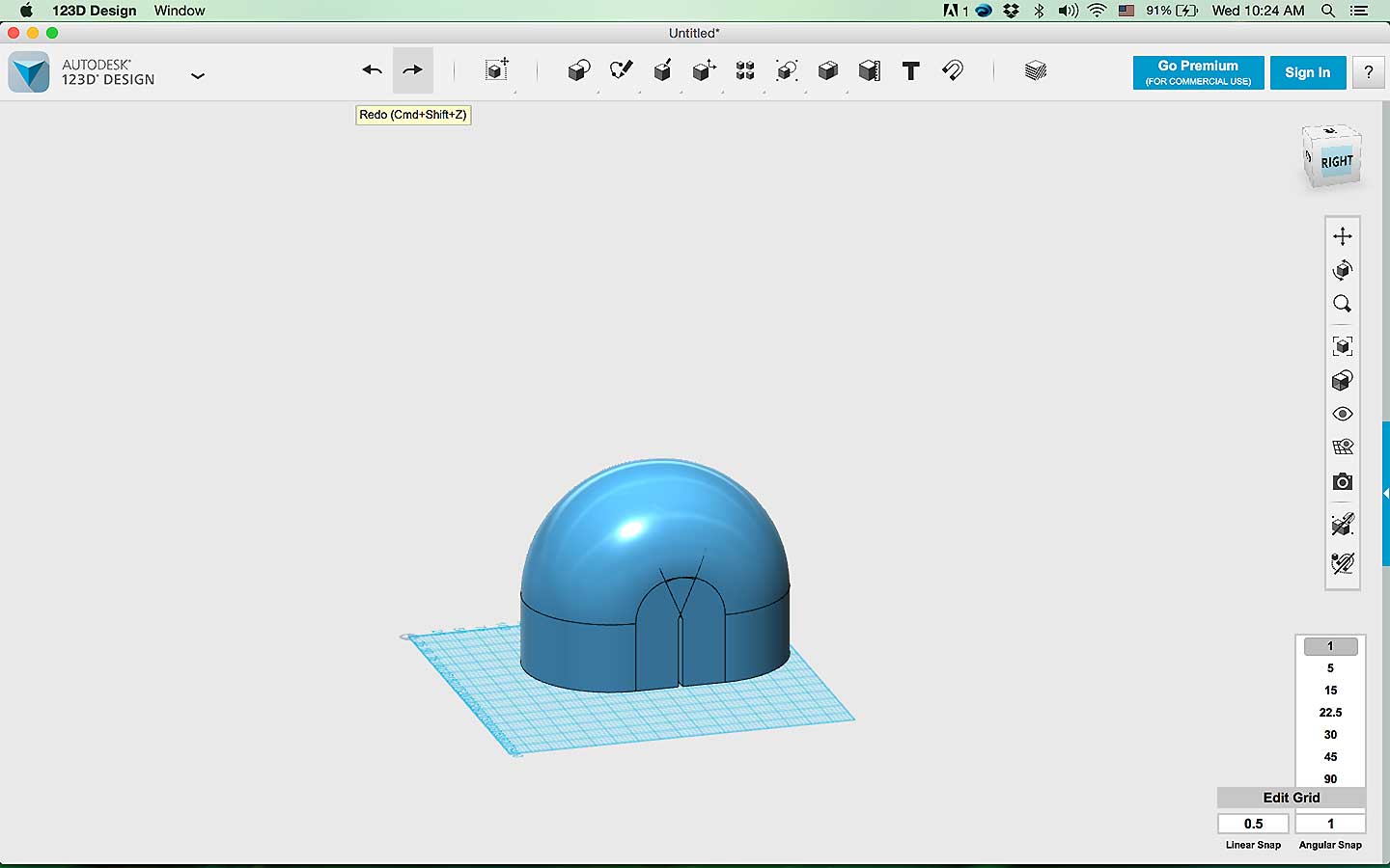
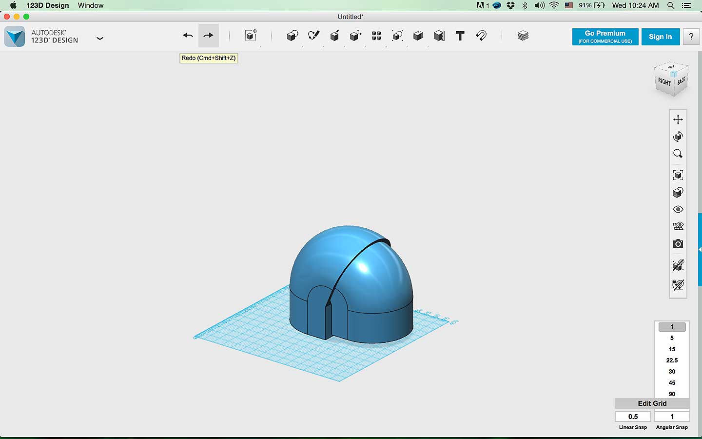
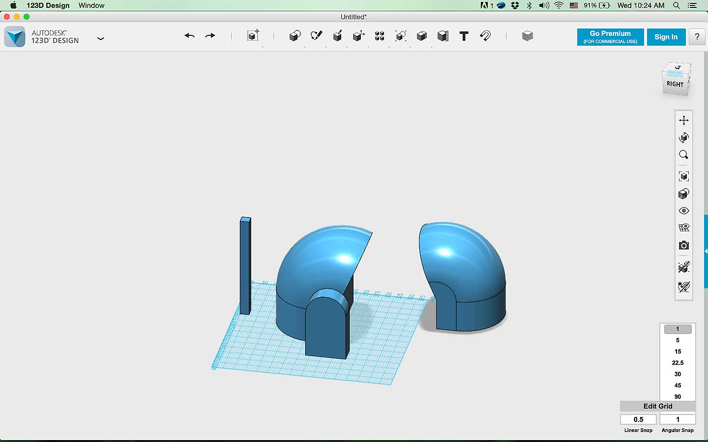
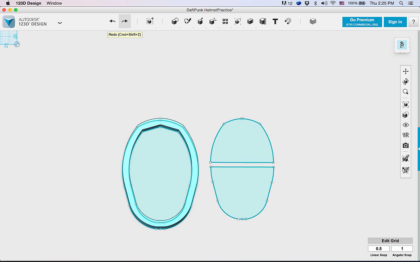
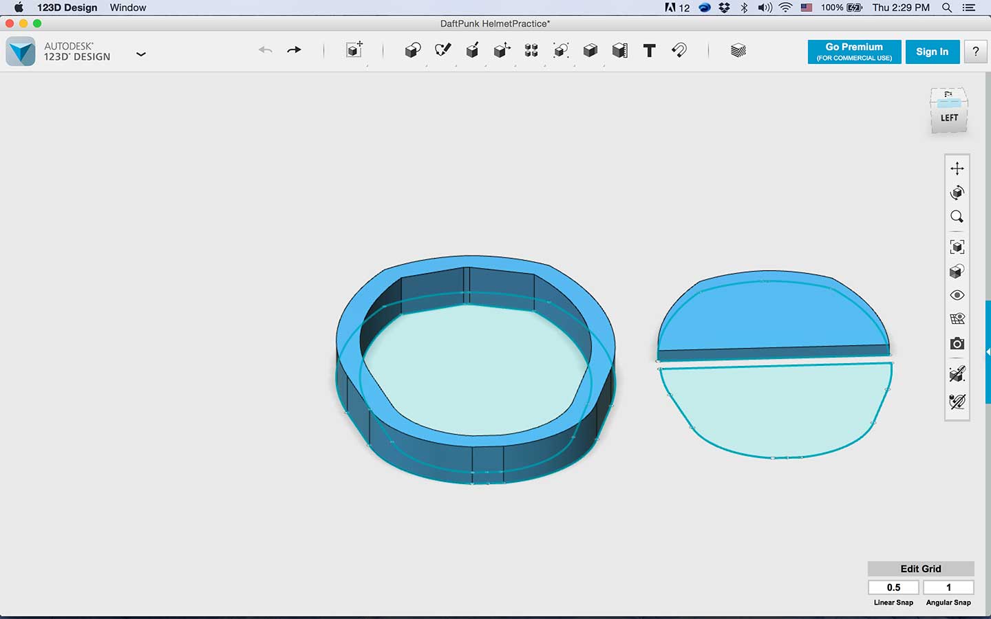
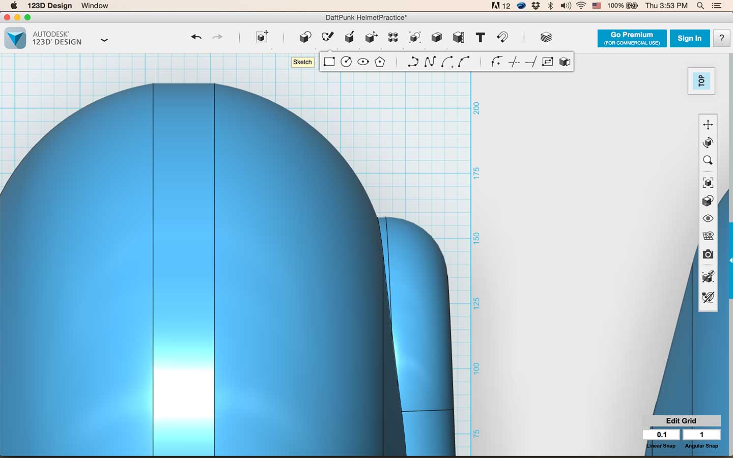
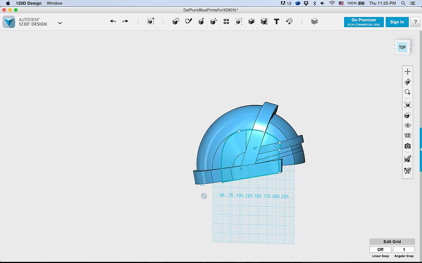
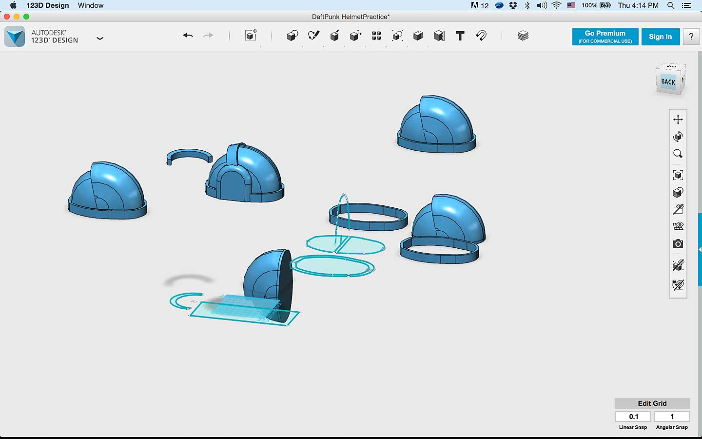
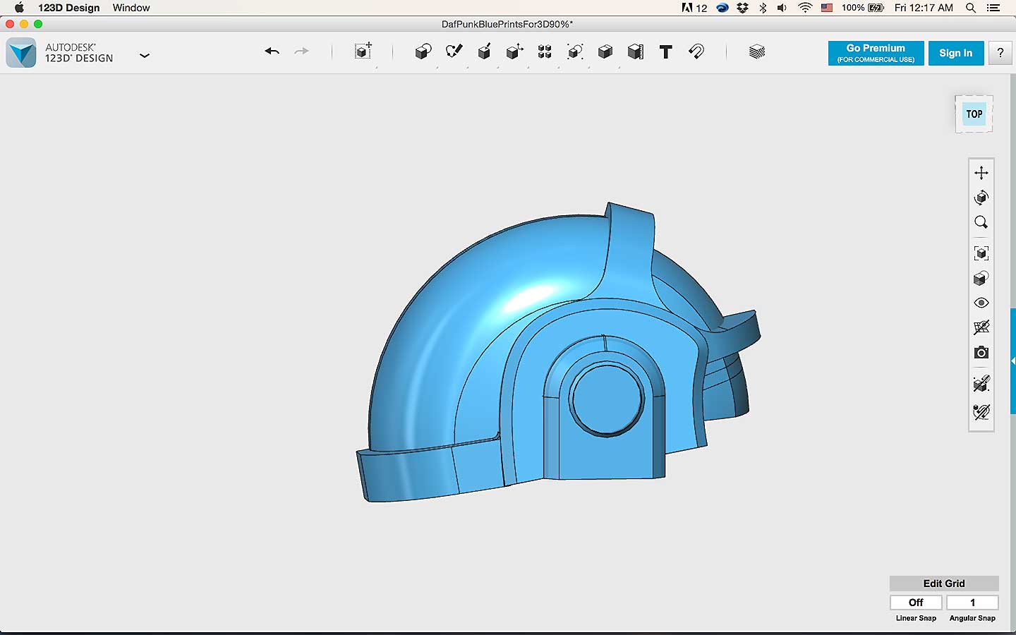
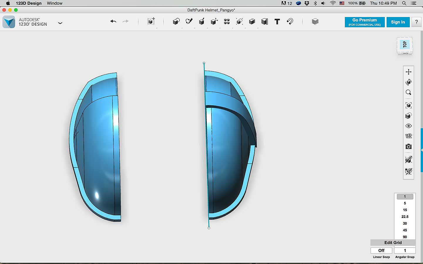
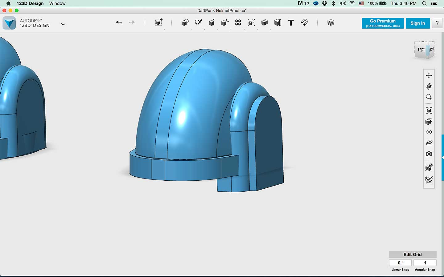
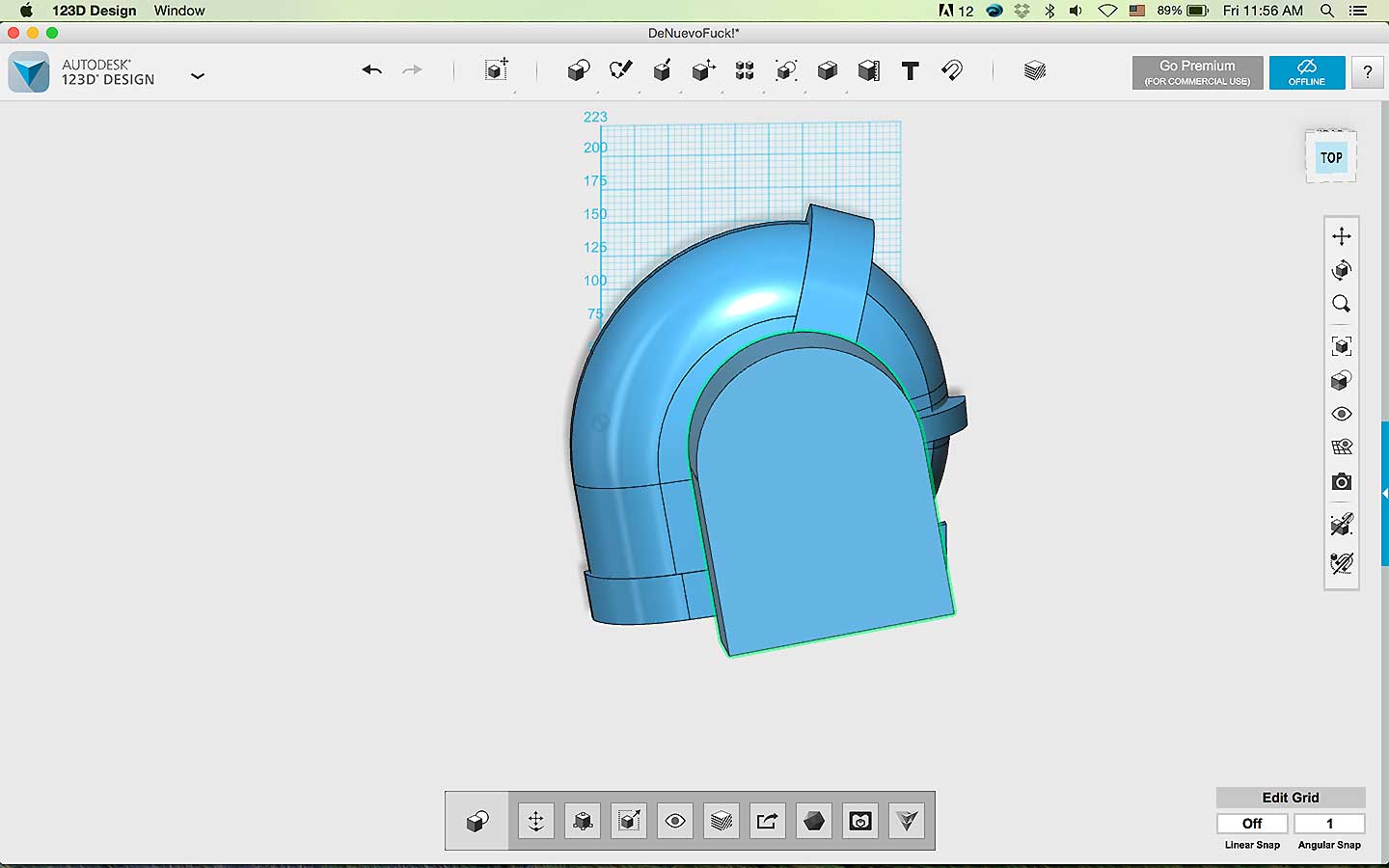
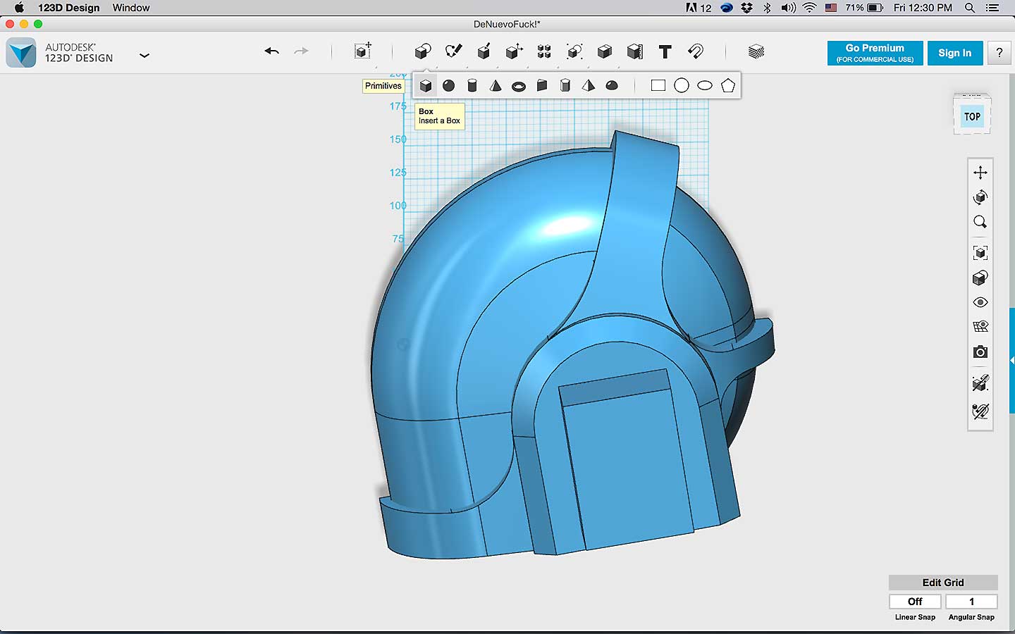
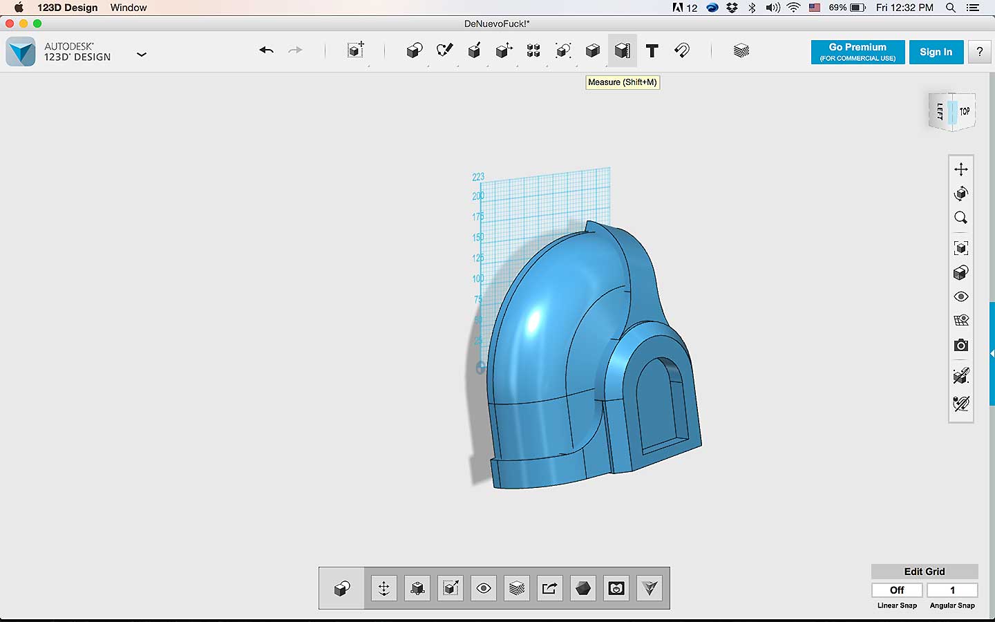
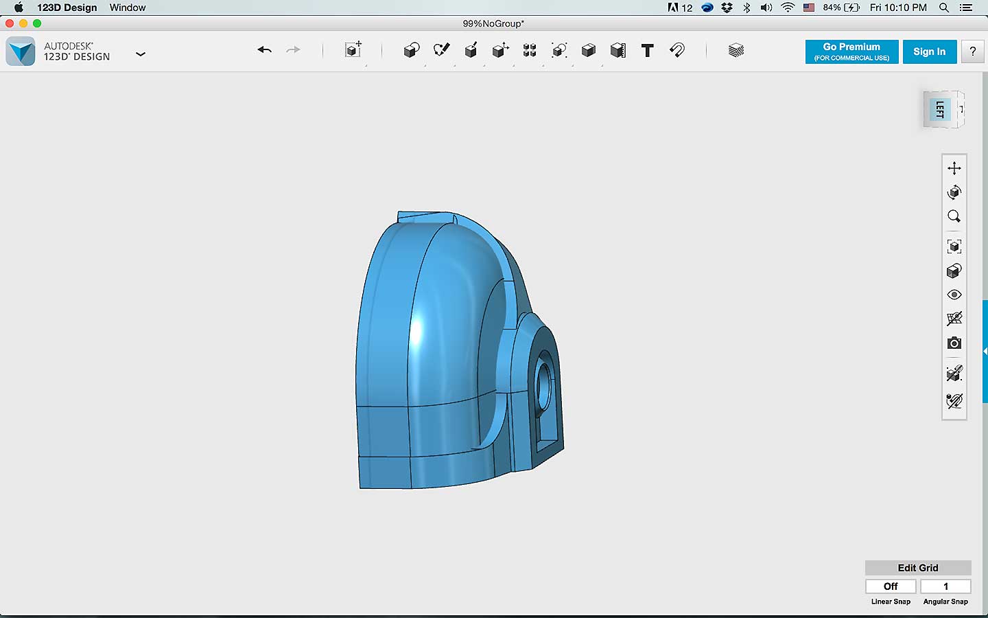
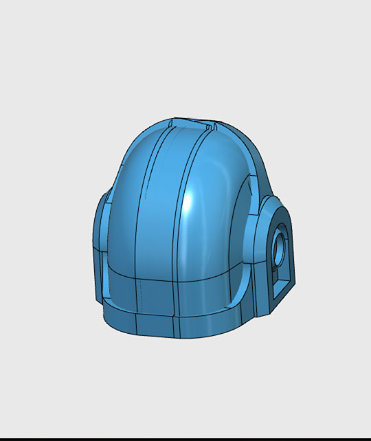
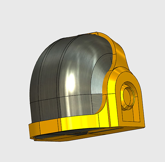
For the 3D modeling software I used the trustworthy 123 Design excellent for begginers and very intuative; However, I think that this will be the last time using this program since Autodesk just announced that will no longer support this pragram from this year.f
- Sketching/Modeling the Final Project
I started with this image as the blueprint to have an idea on how the helmet shoudl look. Once in 123Design I started with an square, cut the corners and I used the revolve option to create the circular visor.
I continue by mirrowing the piece and by moving it untill the back of the helmet was done.
After I started to create to frame, I soon realize that I was heading towars failure because to extrude it from this model woudl not allow me to control the shape as I wanted.
So, I improvise, I Use the blueprint and trace them using illustrator and Autocad to vectorize the img and then convert it to a SVG so I could imported to 123D.
Once that was done, I just play with the extruder and fillets command to create the desired shapes.
For the top bar I just made and sketch and extrude from it.
All this hard work just to realize that the shape was weird and I didnt like it.
So, what I end up doing was, cutting it in half using the "body split" fuction and I desided to work with half of it.
After repeating some of the steps above and bunch of fillers, body split, face and split and combine commands, I finally mirror the half and voila!.
I successfully end up with the model that I wanted!
Downloads
- 123 Design file
- Illustrator vector bluePrints
- stl for 3D printing
Lessons Learnt
What I was not able to do this week:
- Use the programs suggested by Prof. Neil like openskad
- use more parametric design
- being able to conplete the whole table including the legs
What I did but need to get better at:
- Draw a parameter design in Fusion360
- learn how to link file to my website
- Sketch a Final Project
- be more organize with the img and files in my Git repo.
| Week1 | Week3 |