For this week, the assignments to be accomplish are:
Add an output device to a microcontroller board you've designed and program it to do something
Learn something new
Reading time
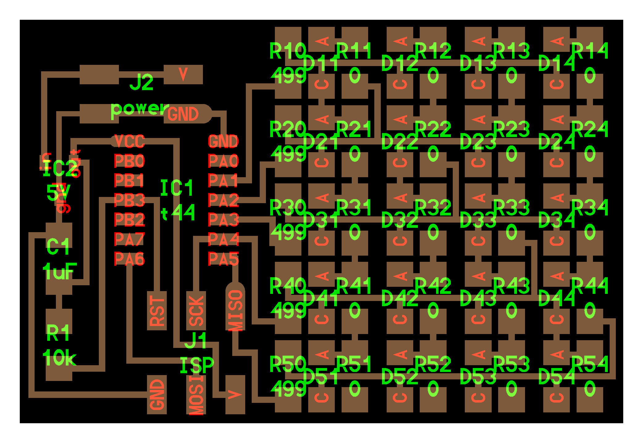
when the professor showed us this board I felt in love with the simplicity and elegancy of it. I wanted to make it and learn how needs to be coded.
This is the sexy Led Matrix that I used as a guideline to make one.
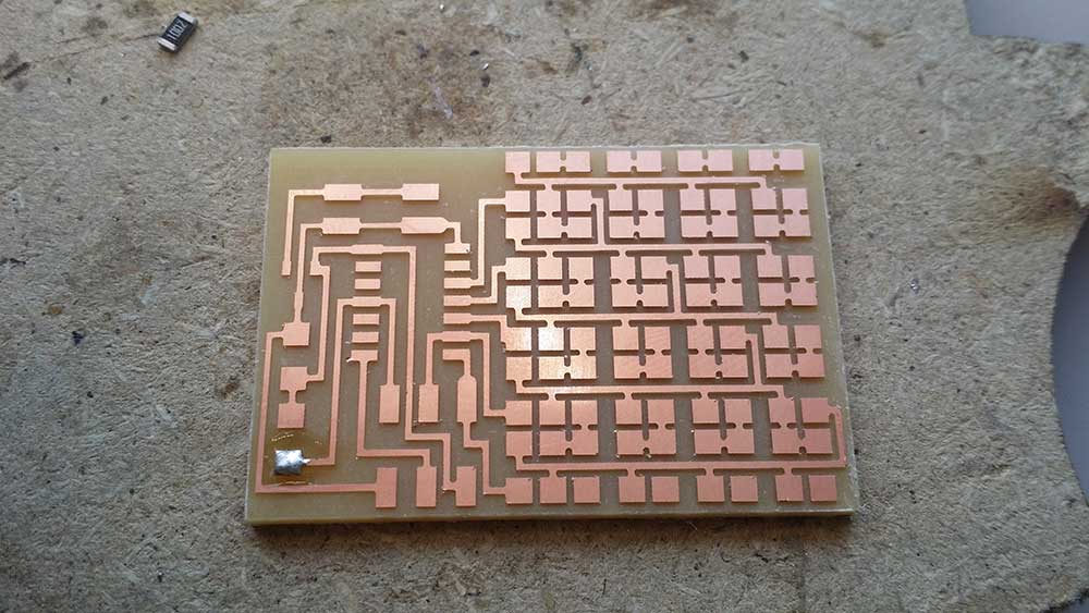
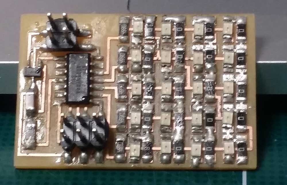
This is the before and after 2 hours of soldering and the nice result was a neck pain.
this is not the video and Im checking
When I took the class, there was too much to digest so I had to think, What's the best way for me to learn what Prof. Neil is Saying!!
Let's make a two board and program them!!. I started with the LED matrix and figure how it works. but after that I wanted to learn how to make another board so I got inspired by DC motor board.
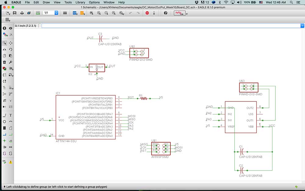
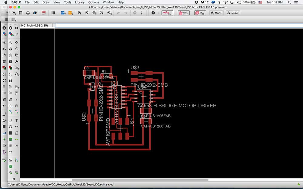
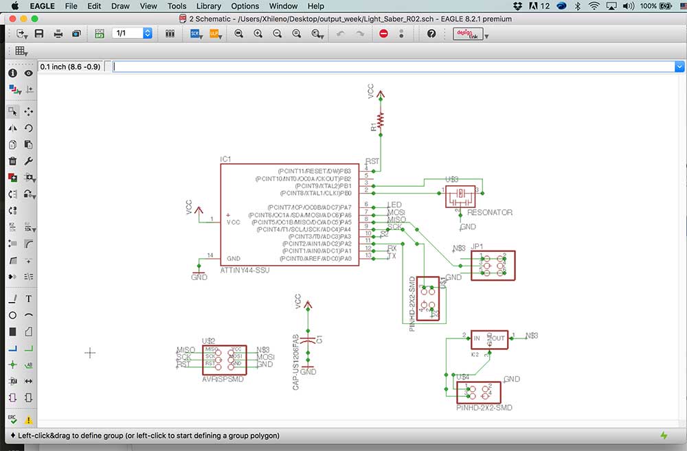
Creating the schematics from Eagle
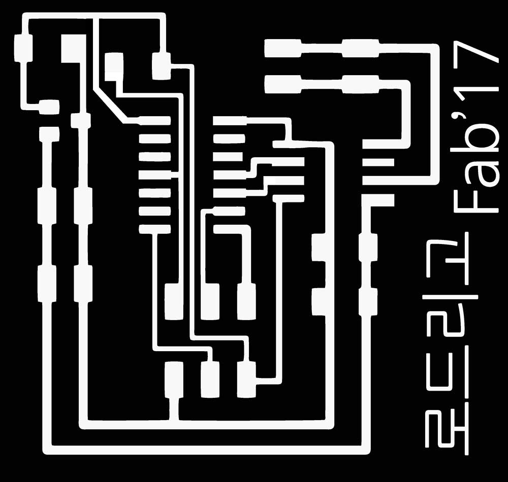
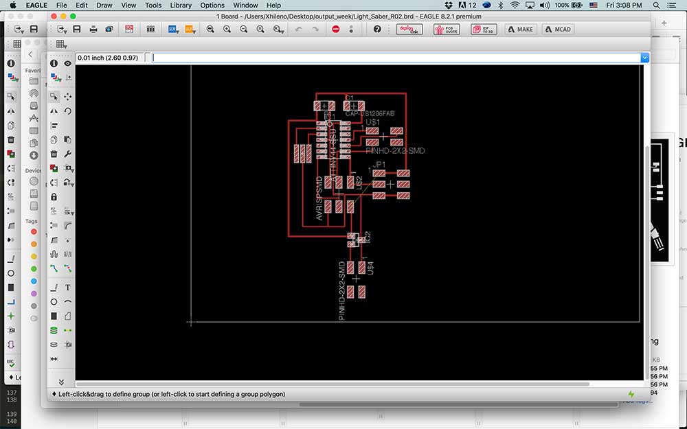
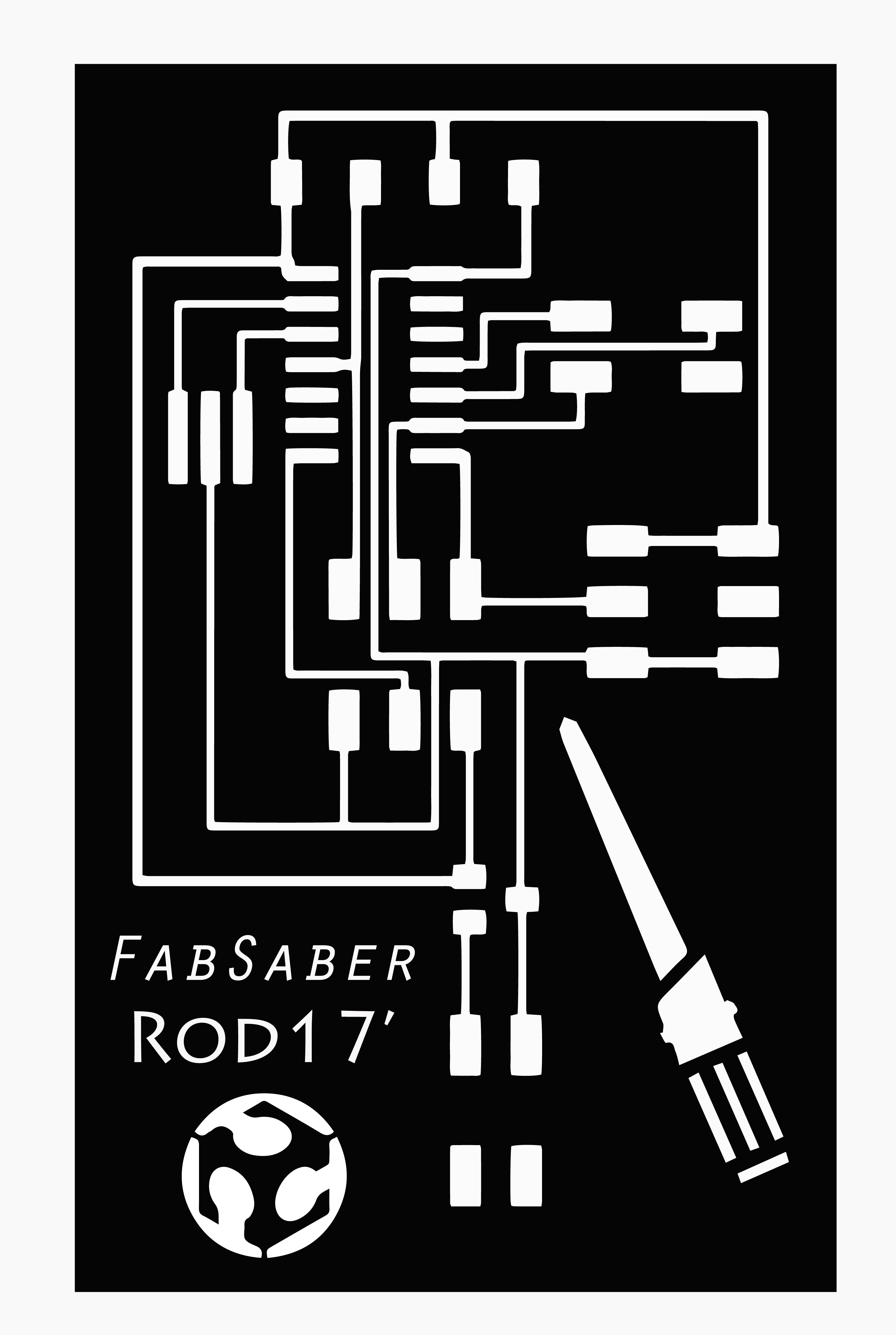
I started making the File Checking ERC and creating the Board to make the traces and check DRC. After I put my name on it and cut it!
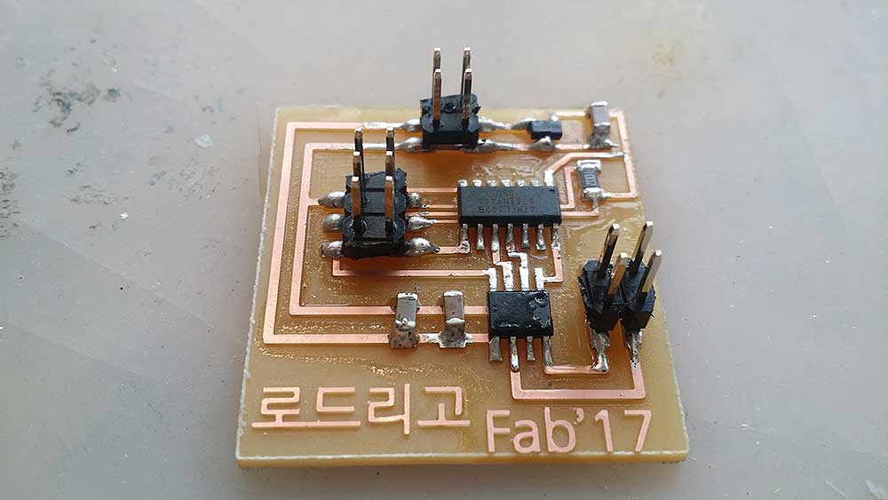
Soldering and Programing and trouble shooting!
I replicate the board that the prof. Neil has in his website but this time I had to learn to understand how it works and read the H-Bridge data sheet and the voltage regulator to understand the requirements for the Attiny44, H-Bridge and voltage regulator.
List of problems that I encountered trying to make this board
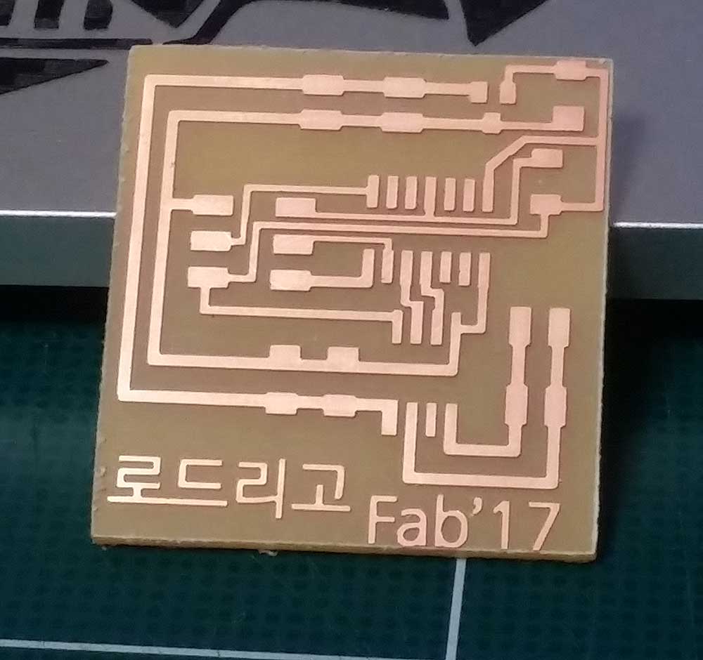
I realize that I was doing the outside of the PCB wrong!! I save the board by "Air Cutting" and checking the tool path untill it was right!
Burn two(2) voltage regulator!! I just changed them!
Burn a Attiny44 ㅠㅠ!!! cause I burn the voltage regulator and it was direct voltage to it and was burned!
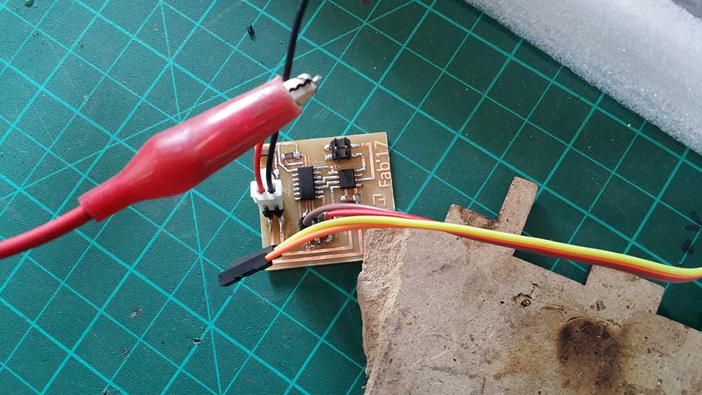
I did assamble the board and it worked ok. However; when I connected 9volts to use it with the motor I burned the voltage regulator, I check the connection and solder a new one, and again happend the same.
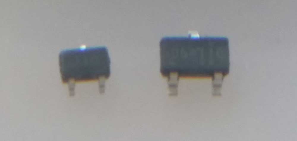
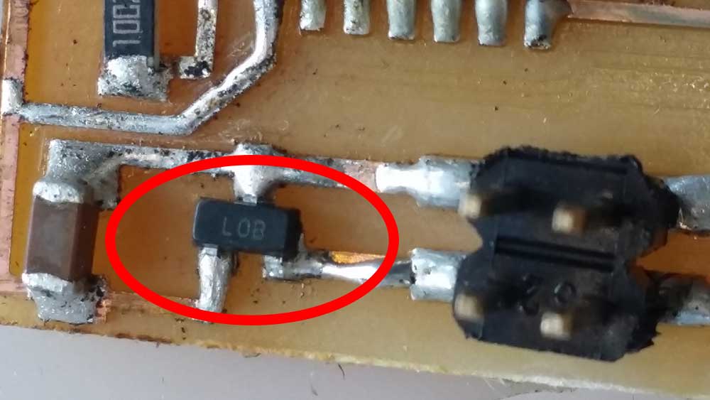
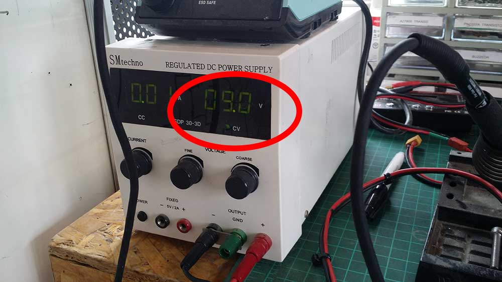
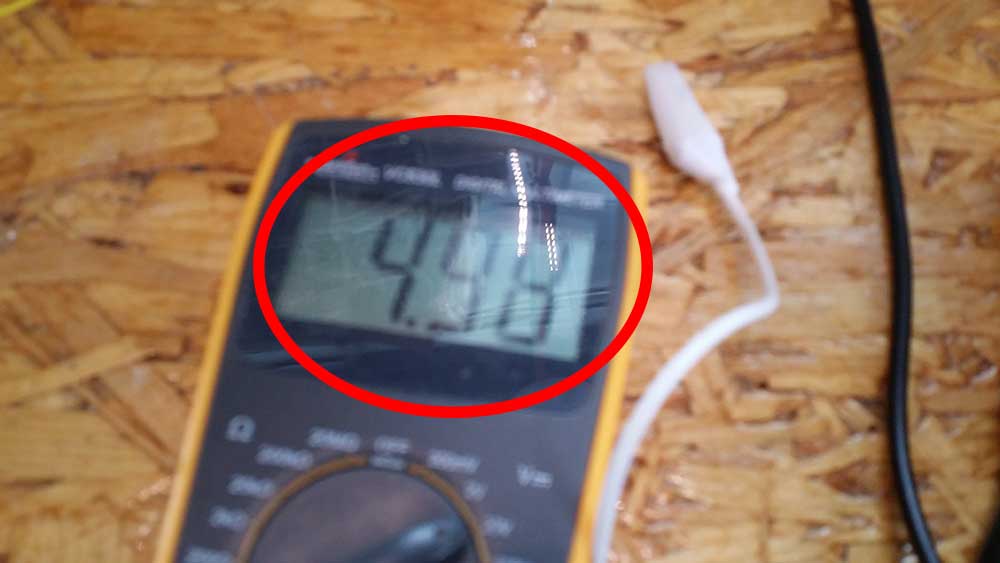
Luckyly our instructor had the same board and when I looked at it carefully I notice that the labeling name on the package was different. Zooming pictures revealed me that ven the size was defferent. thus, I changed soldered and connected 9v to it and voila 9v comming in 5v comming out
For Some reason I was not able to make my DC motor move, I did connect my instructor,s board and the DC motor moved I did the same connection and I tested mine and I was able to bootloader meaning the Att44 was ok so I think I burned the bridge. I was about to continue when I realize that I should probably making a board for my Final project so, to be continue...
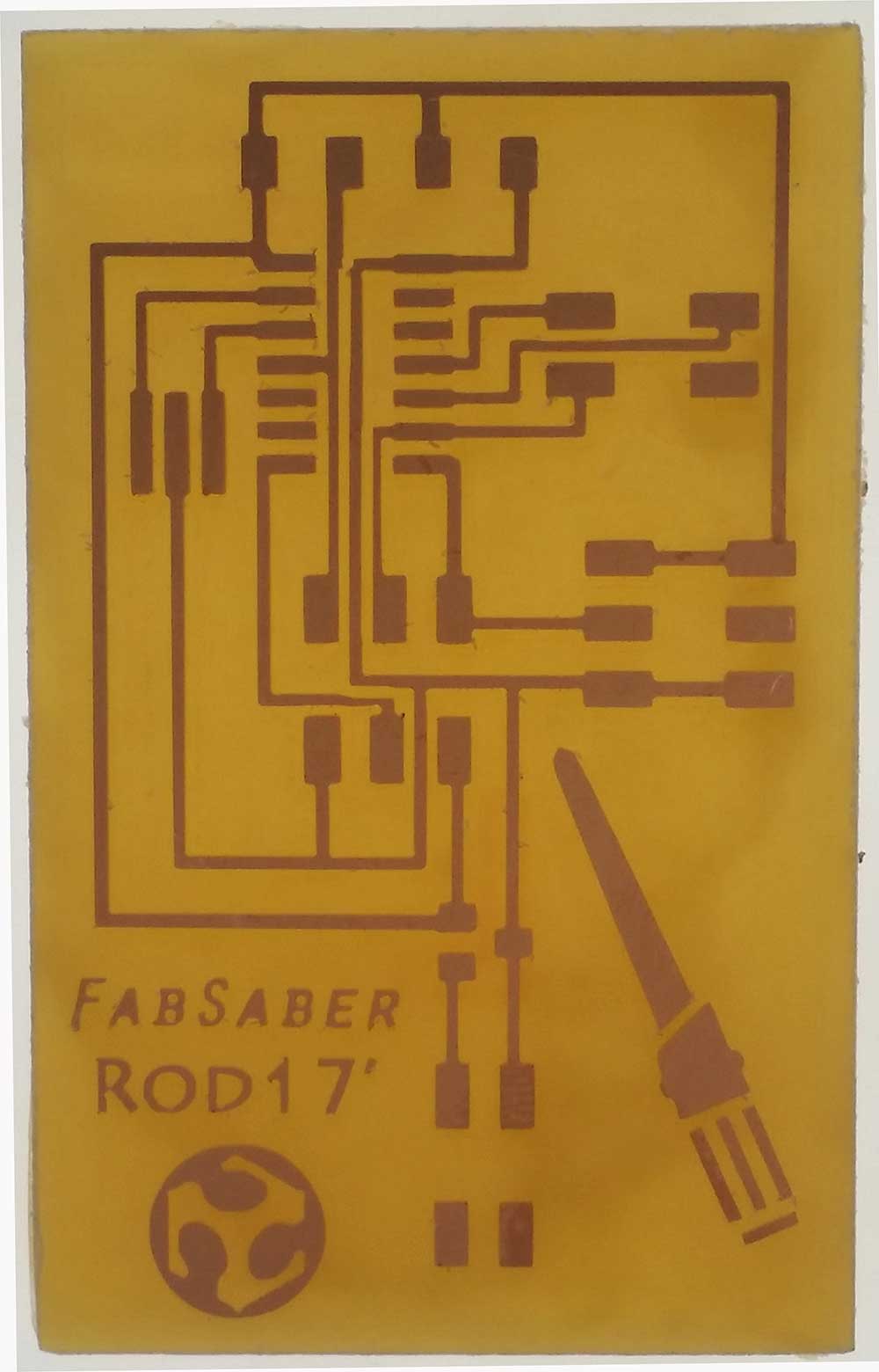
I want to make a light saber so I want to use adressable led (neopixels) so I can make the animation from bottom to top light up just like the light saber, I read the Neopixel data sheet and I realize that I dont know how to used the pixels I did play with the adafruit library using arduino and my life was great!!
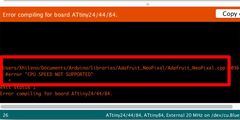
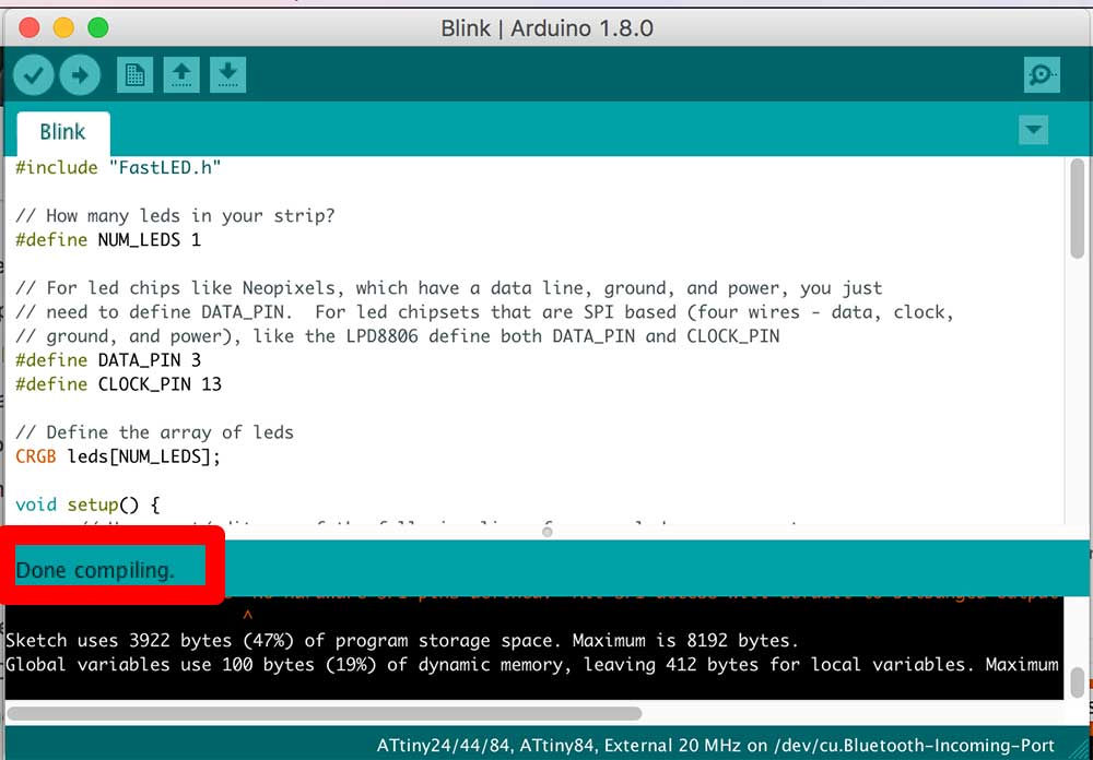
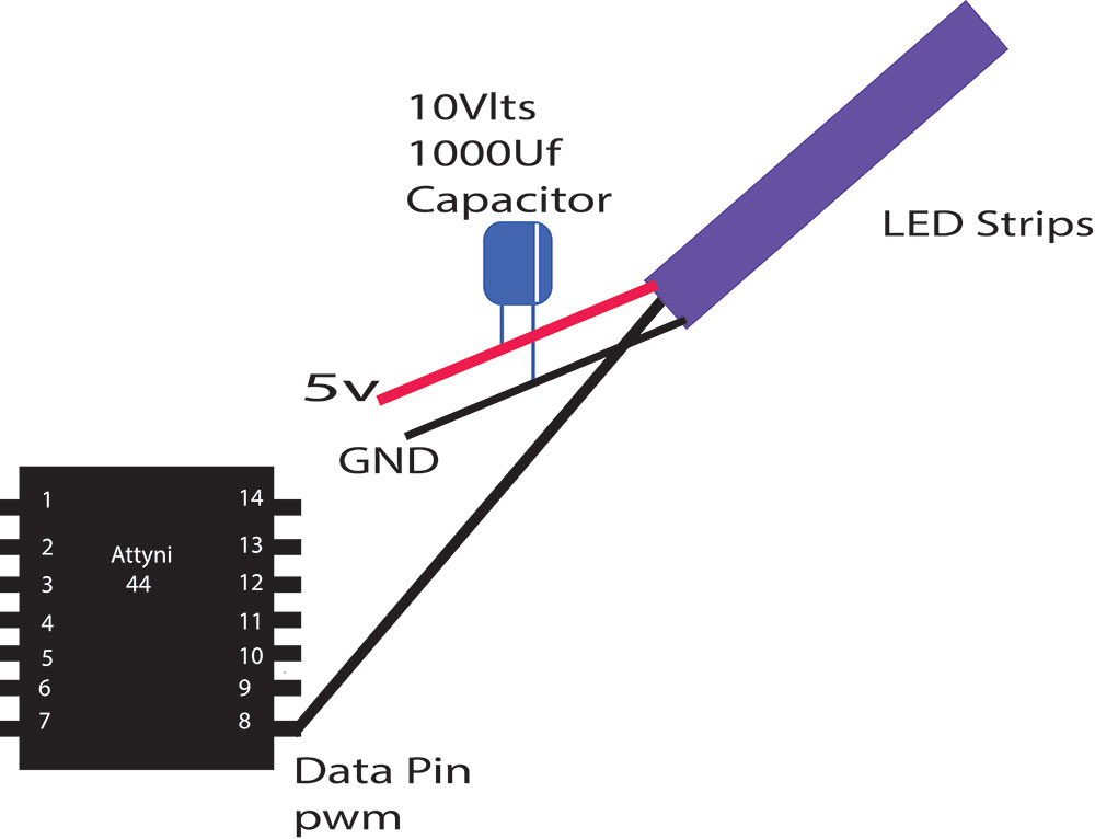
Here's my eagle file This is after I cut it. I discovered that you can check the compatibility in the IDE by compiling it using the Attiny, clock speed (external of internal) and it will give you how much memory your sketch uses. This is a simple diagram to guide you how I connected my LED strips to the board. I didn't have big problems beside the Adafruit library (didn't support the 20mhz but 16) so I download the Fastled library that had support for the external 20Mhz resonator and magic!!!