Week 10: Output Devices
This week our task was to "add an output device to a microcontroller board you've designed and program it to do something". We were inspired by the Drawio pencil from Make magazine
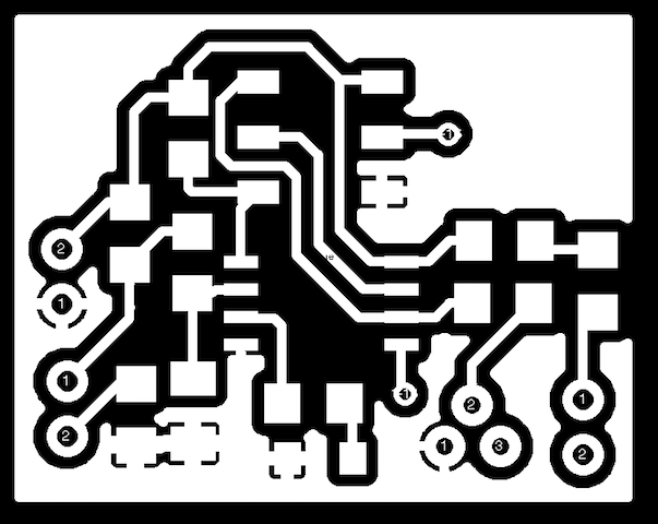
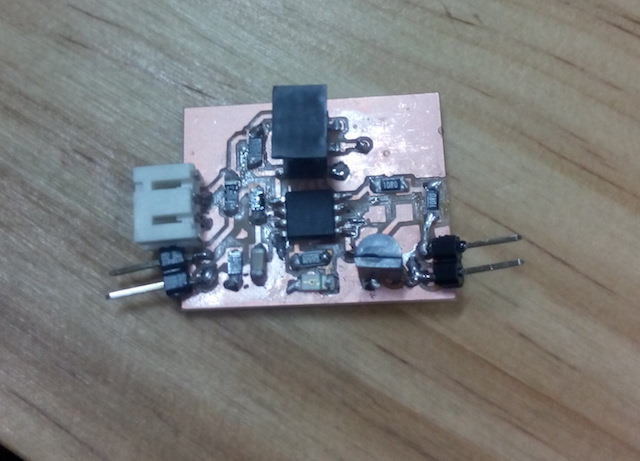
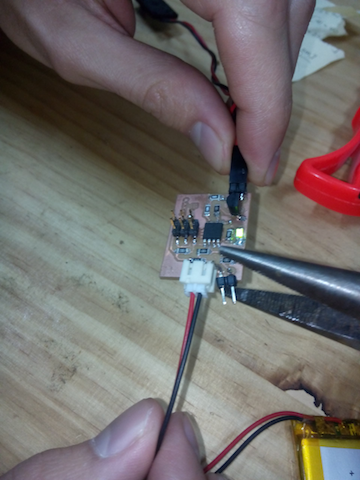
To begin, we changed the integrated circuit for a microcontroller to allow it to be programmable - instead of the TLC 555, using the ATTiny85 microcontroller, and adapting the circuit design from this project I designed the circuit with Eagle, then fabricated and tested the board for short circuits. There were some problems that required desoldering, but finally the board worked well.

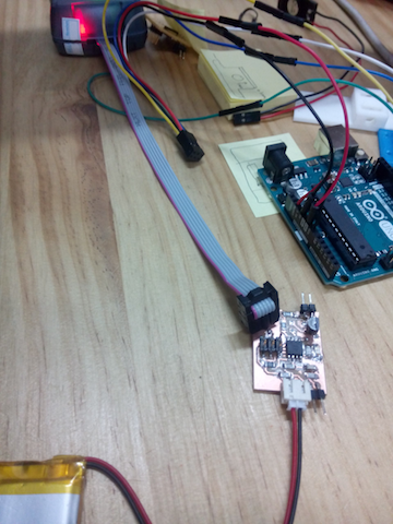
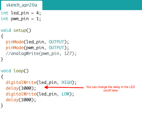
I then played with programming the board to talk to the LED as the output device. I used an Arduino to program the board. I then changed the time interval set in the program that talks to the ATTiny85 clock settings. I changed the time lapse of the LED turning on and off, and then linked up the board to a mini-speaker as a second type of output device.
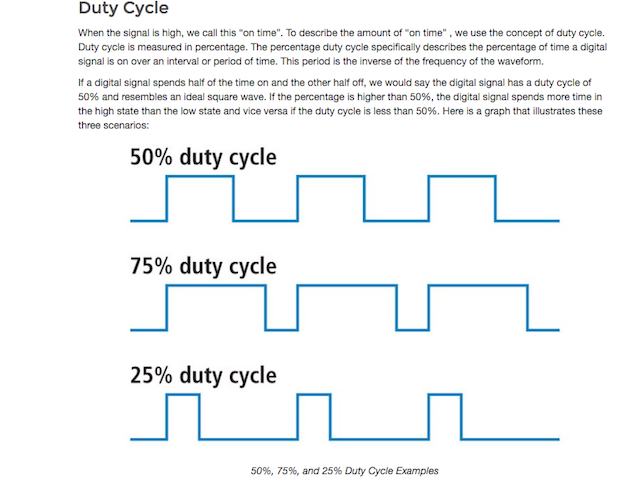
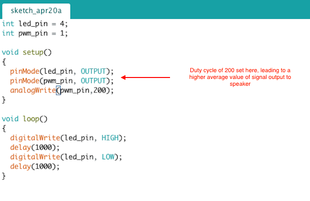
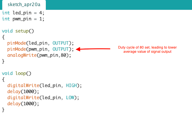
I then played with programming the duty cycle for the analog output of the speaker. Our code just changes the volume, not the frequency of the signal. Because there is a 3.7 V battery linked to the board, this theoretically should put an upper limit to the duty cycle. However, we measured but the full charge as 4.15 V. Here the speaker is the transducer - taking a digital signal with a certain duty cycle and transforming it into an analog (pressure based) sound signal. When the duty cycle increases, the average value of the signal increases, which translates into an higher volume.
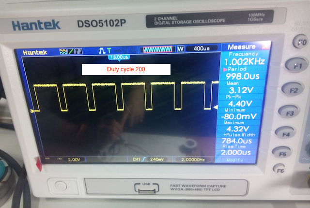
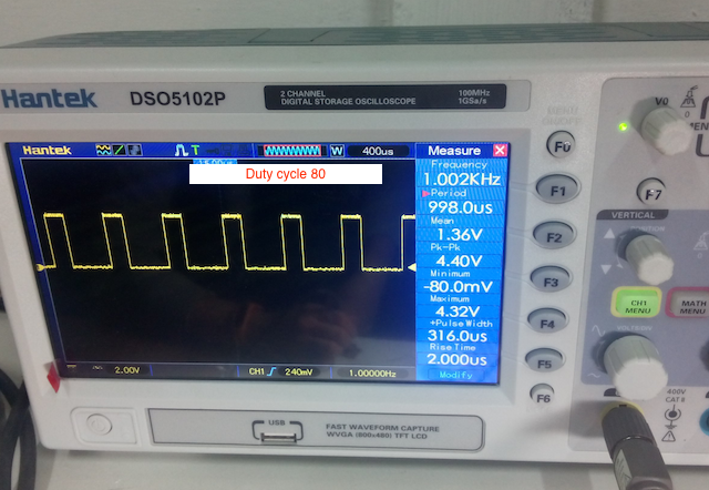
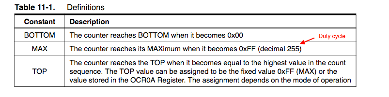
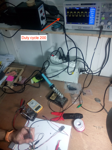
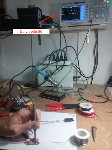
In terms of the code, I learned that the ATTiny has a 255 duty cycle, which has to do with the 8 bit register programmed in the chip, creating 256 values (counting 0). This is shown in the ATTiny85 In the data sheet. I played with changing the duty cycle in the code by alterning this number, changing it from 200 to 80. By linking the board up to the oscilloscope I could visualize the change the duty cycle (as programmed in the code).
Hero shots: see below for a video of the speaker working as my board output, as well as a picture of the LED turning on
Here are the files from this week:
Board Holes Board Mill Board Cut Board Image Traces Board Image Holes Board Image Cut Board Eagle Board Eagle Schematic Code