Assignment Week 3: Computer Controlled Cutting
This week our task was to understand the basics of parametric design. The requirements for this week were:
✔ make lasercutter test part(s), varying cutting settings and slot dimensions
✔ design, make, and document a parametric press-fit construction kit,
accounting for the lasercutter kerf, which can be assembled in multiple ways
✔cut something on the vinylcutter
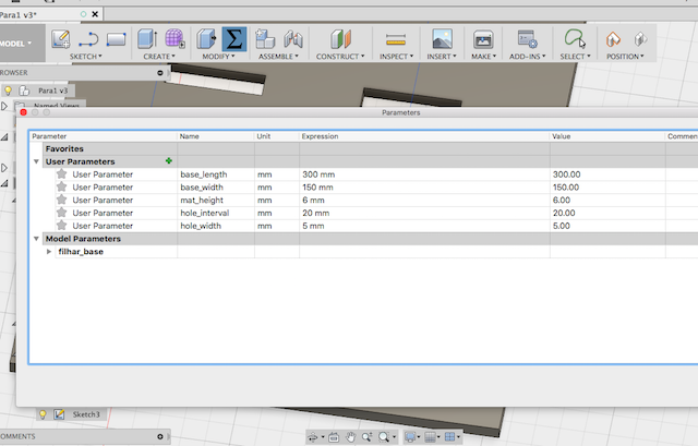
I used Autodesk Fusion 360 to come to grips with parametric design. After watching some tutorials, I figured out the basics of specifying parameters in the window that constrain the dimentions of the parts. I chose to begin the design process of my final project - an apparatus to measure the material properties of samples based on their resonant frequencies Click here to view my project page
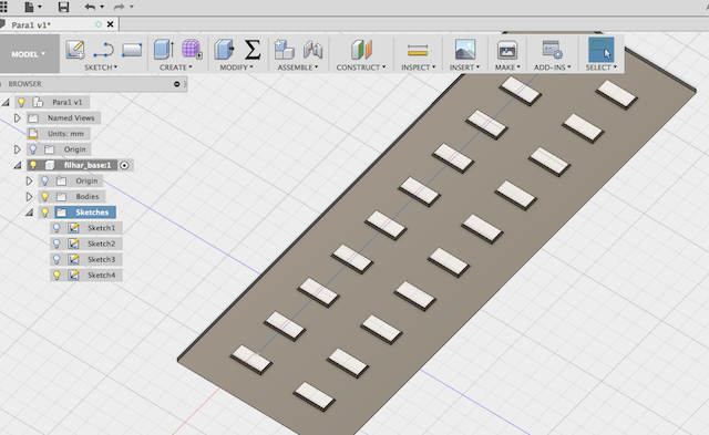
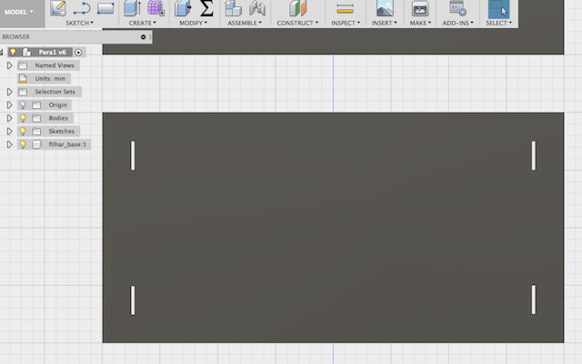
One of the unexpected lessons from this week was the importance of following a clear design process. At first, I created a base and specified the parameters. I then extruded it to the width of the cardboard I intended to use in the Fab Lab (3mm), and then tried to create holes with the right dimensions (see pictures above). The problem was, I found it difficult to line them up properly on the extruded surface. After trying many techniques, I went back to the drawing board.
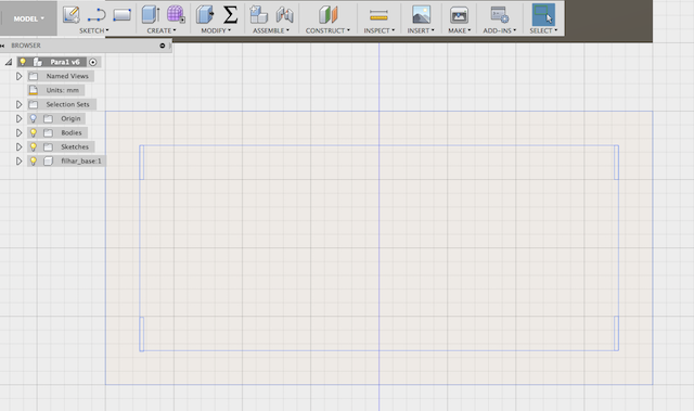
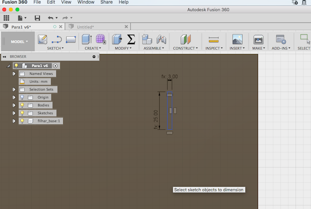
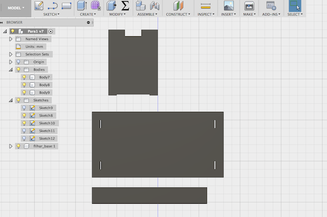
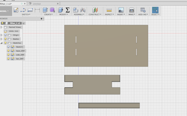
I started using the 2D sketch tool, and quickly found that if I planned everything ahead, I could design everything in 2D, and then extrude only the parts I needed (excluding the holes). This made it easy to line up everything perfectly - the sketch tool is much more precise than designing once the shape is extruded (pictures above)
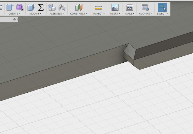
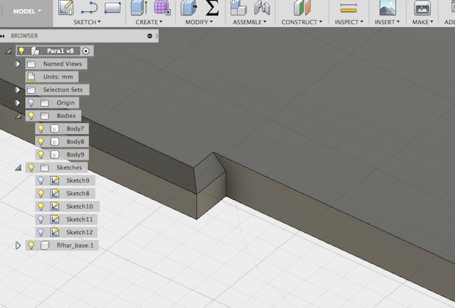
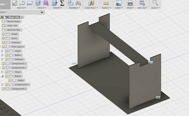
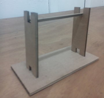
After getting the design process sorted out from 2D to 3D, I quickly designed and extruded the parts of the whole assembly. I tried adding camphors to the edges to help with the press-fit assembly once laser cut. I added two (one on each side of the piece) on one side, and one on the other to compare results
I then figured out how to assemble the pieces with the "assemble" tool, and it all fit. This was a good way to check that the dimesions of the pieces were designed correctly
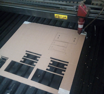
Next came the laser cutting. I saved sketches from each of the pieces into DXF files from Fusion. The I used illustrator to import them and save them all onto a single file. While I learned that I should save each component of a model as a seperate sketch, and then combine them into one page, I made the mistake of using the same sketch for all of my pieces. This turned out to be okay when it came to the 2D sketch, as I could import a sinlge file into Illustrator, and it had all the pieces. From there, I saved the single DXF file onto my USB stick and took it to the laser cutter computer.
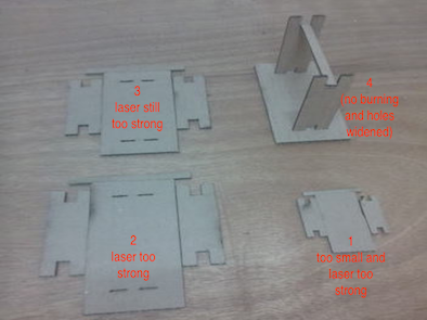
At first, the dimensions I had programmed were way to small, and I had to adjust it on the laser cutter software. This made it less precise, but it was a good learning point, and as all the pieces were scaled proportionally, it didn't matter too much. As you can see below, the first cut was still very small. The laser cutter settings also needed to be adjusted in terms of strenth and speed. The following lists the 4 experimental cuts in terms of the range of power settings tried (range indicates minimum value to maximum value):
- 90-100%: badly burned
- 70-80%: burned
- 50-60%: slightly burned
- 30-40%: no burning (good)
The other change that had to be made was the size of the holes. Although they fit exactly in terms of dimension, it was useful to make them a bit bigger. This allowed the final fitting together (see image below) of the designed test aparatus of the filharmonic.
Taking the assignment a step further, now came the need to create a parametric press-fit model that could be reconfigured. For inspiration, I decided to create a press-fit model for elasticity testing can be reconfigured on the basis of different material sample sizes and geometries. Below you can see the first sketches of such a design.
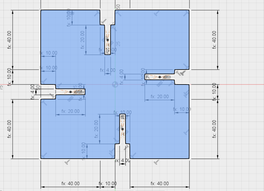
After a lot of sketching in my notebook I came up with the following design for two pieces that offer a lot of flexibility when it comes to reconfiguring the overall model.
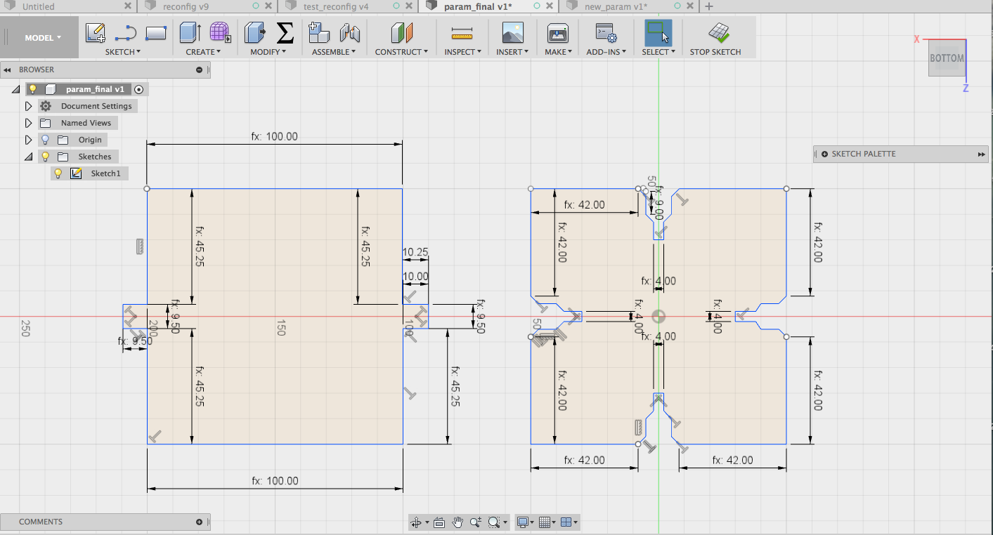
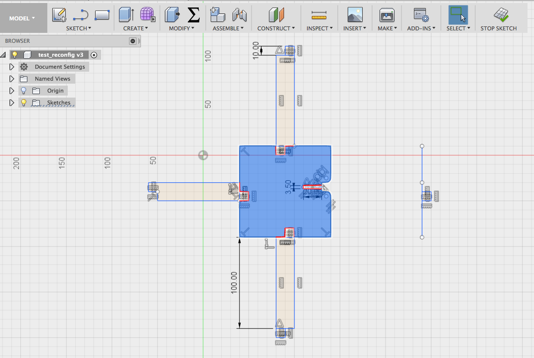
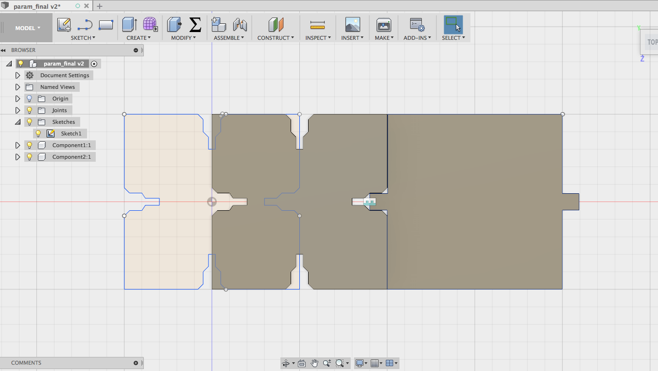
As you can see in the Fusion 360 sketches, I made sure that the pieces were (a) parametric, and (b) used press-fit style joints so they could be pressed together easily in multiple ways while retaining structural integrity. I played around a bit with the parametric measurements. Below you can see what happened when I altered one parameter without making a change in another. Fusion usefully points out how the model is skewed by noting where the right angle is on the canvas.

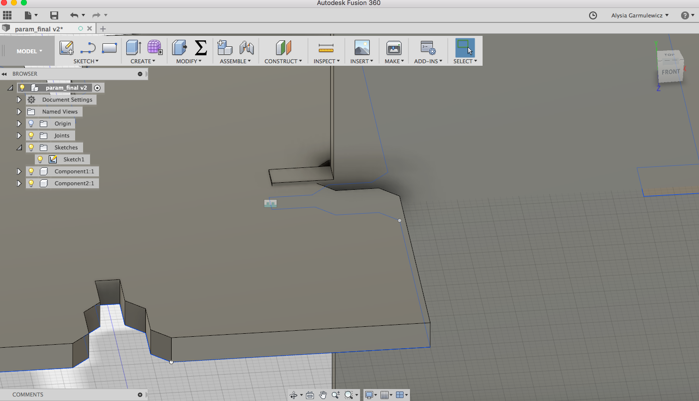
I extruded the pieces to create a 3D model and then tested the 2 types of joints by creating components and selecting 'joint' in Fusion
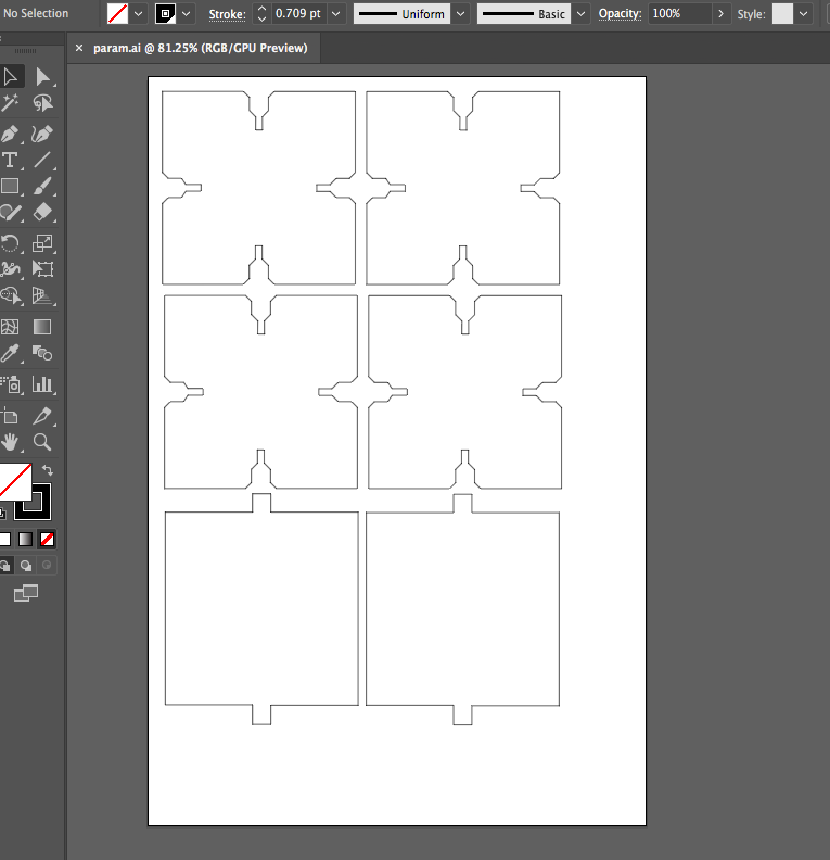
I exported the pieces to Illustrator, and played around with arranging the pieces so they could be cut in batches. However, when I turned to the laser cutting software, this step ended up being redundant, as it was easy to manipulate the dxf file (exported from Fusion) in the laser cutter software (duplicating and arranging the pieces to fit the dimensions of the cardboard I had available). The pictures below show the illustrator layout as well as the layout in the laser cutter software.
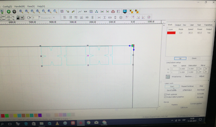
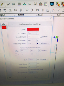
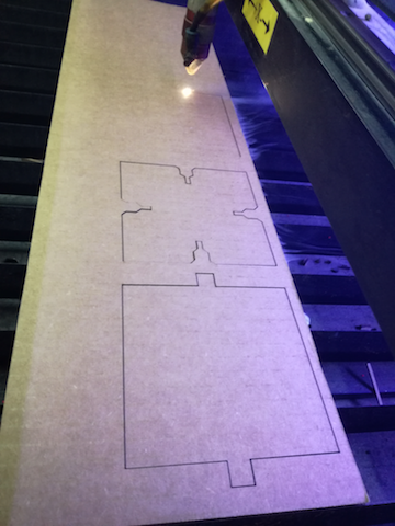
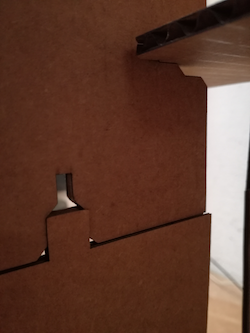
A close-up of the settings I used for cutting the cardboard is seen below, along with the cutting. The width of the cardboard used was 4mm, and the power used was 60% (max and minimum). This was a good setting for cutting through the thicker cardboard without causing burning. The speed was programmed at 30mm/s.
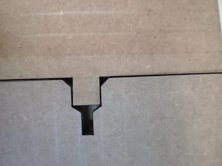
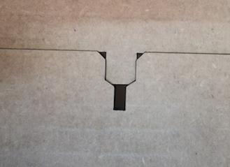
However, there was a problem of fit with one of the joints - it was too loose (picture below, left). I fixed this quickly by adjusting it parametrically (increasing the size of the insert by 1.5mm). Then it fit perfectly (see below, right)!
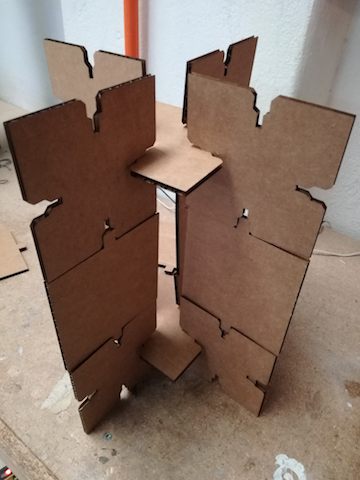
Here are the piles of cut pieces. I assembled them in different configurations inspired by the different sample set ups for testing (see final project page for the eTester method). The following two show a set up that is designed for circular samples to be supported by the edges.
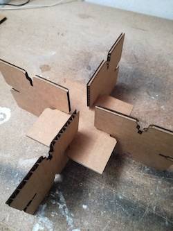
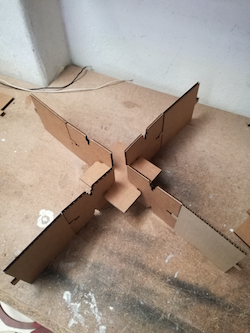
The following two allowed a test sample to be balanced on one edge or two edges. The latter is also extendable to account for different sample dimensions. For more details on how these setups relate to elasticity testing, see the Final Project page.
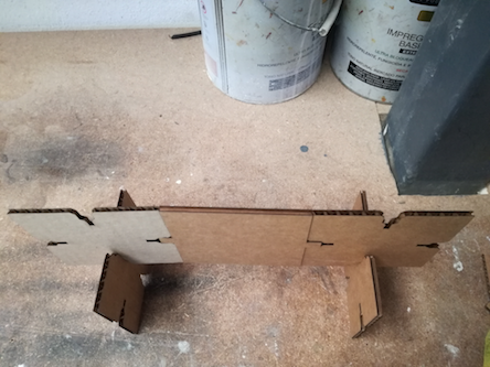
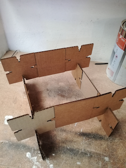
One of the most important parts of the design was the 'double purpose joint', allowing the sideways joining of the pieces (designed to be joined according to the width of the material itself), as well as the insert joint that allowed the two differently designed pieces to be joined creating a flat surface. This multifunctional joint increased the reconfigurability of the overall model.
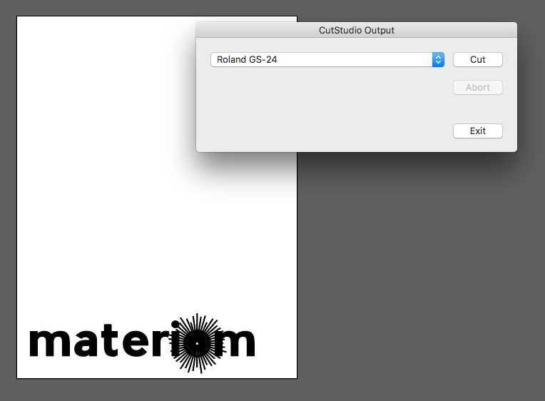
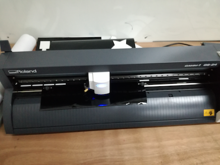
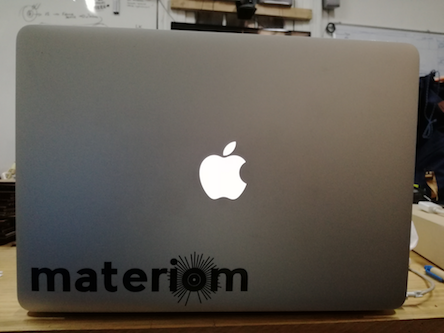
Then came cutting something on the vinyl cutter (Roland). I decided to cut a new version of the logo for Materiom, the platform for local materials my final project will be contributing to. First I took the logo in illustrator and exported it via the Roland CutStudio plugin to the laser cutter.
I chose black vinyl (3M Scotchcal 300 Series) and adjusted the roll so it was lined up with the white rollers. The settings were:
- Speed: 5cm/s
- Offset: 0.125mm
- Force: 120gf
After it cut, I then carefully peeled it off the vinyl, and transferred it onto the transfer material (a type of plasticised paper). In the picture below (right) you can see me applying pressure to make sure the sticker was properly transferred.
![]()
After this stage I applied the transfer paper to my laptop, once again applied pressure, and then carefully peeled it off. Success!! I enjoyed making the logo very much - I was astonished at the speed of the cutter! It is really easy when you understand the process.
Here are the files from this week:
First model files
Bar file
Base file
Side file
All
Reconfigurable Model files
Illustrator file
Model Pieces
Vinyl cutter file
Illustrator file