Week 2 - Computer-aided design
Week 2 was all about computer-aided design i.e. CAD. Fab academy has a large colletion of programs listed for students to get acquainted with. It is recommented that student test as many programs as possible and select few to do the weekly assingment of modeling the final project with them. List can be found under 2017 schedule here.
2D programs
I started the weekly assignment by looking through the listed programs www-pages. Just looking quickly what the programs are about. Some of them were familiar but many were totally new to me.
After going through each programs the www-pages, I selected few programs that I installed to my computer for more close inspection. First program I did install was GIMP. It is a capable raster image manipulation software. Previously I have used Photoshop when I needed to work with Images. So it was interesting to see the difference. For some reason I did not find GIMP easy to use with my Photoshop background. So I decided to stick with my Photoshop for the future.
But as this week we needed to try new software, I did some drawing with Gimp. As my 2D-drawing skills are non-existing I just did a sketch about my final project from one angle with some details on it.
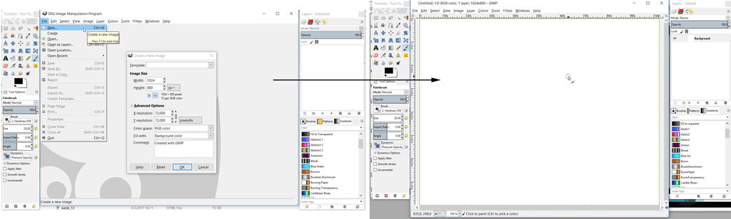
When starting Gimp, it will open without new image. So first thing is to create a new image. This is done from File -> New. There are options like image size and resolution that can be selected to start with.
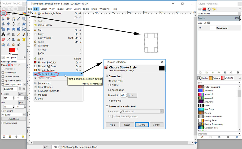
Then I created a box using Rectangle select tool from tools menu. To make a box out of it, I used Edit -> Stroke Selection. From there line style and width can be selected. The result is a box with line color chosen.
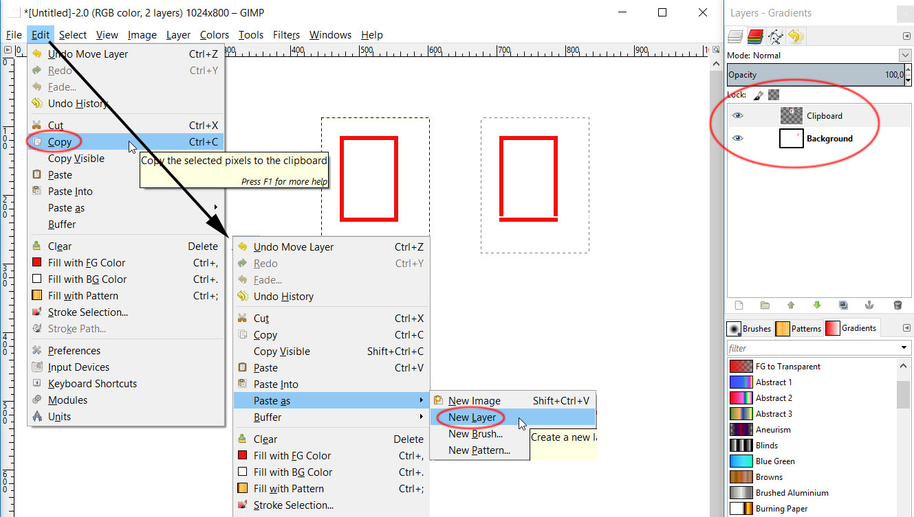
Copying box with Edit -> Copy and Pasted it into a new layer (that can be seen on the right) using Edit -> Paste as -> New layer.
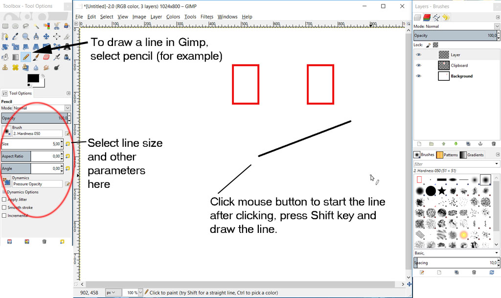
Drawing a line in Gimp is quite a weird prosedure. First select pencil for example (other tools make lines as well) select the properties of the line from the tool options window. Now to draw a line click your mouse left button (Windows) on the starting point. Before moving cursor or anything press the Shift key and start moving you mouse to the place you want your line to go. To finish the line click mouse button again.
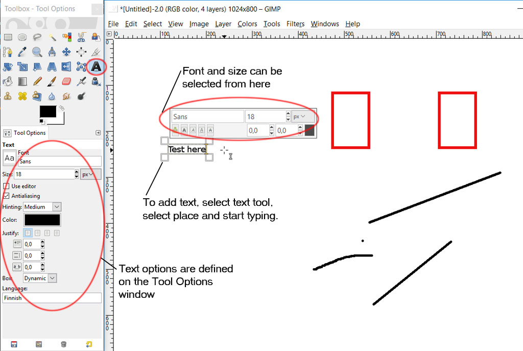
Adding text is quite easy, select the text tool from tool box, select font, size etc. and click to start typing.
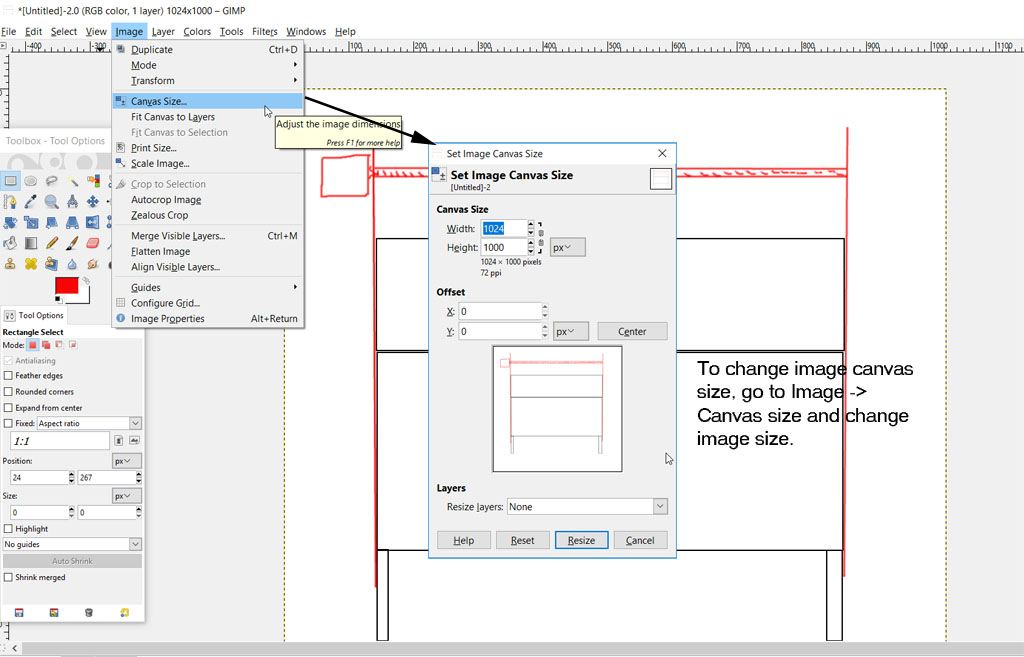
To re-change image canvas size, go to Image -> Canvas size and make the changes.
Using mainly these tools, I draw a picture of all electric components on my final project. Not as actual components but as a diagram.
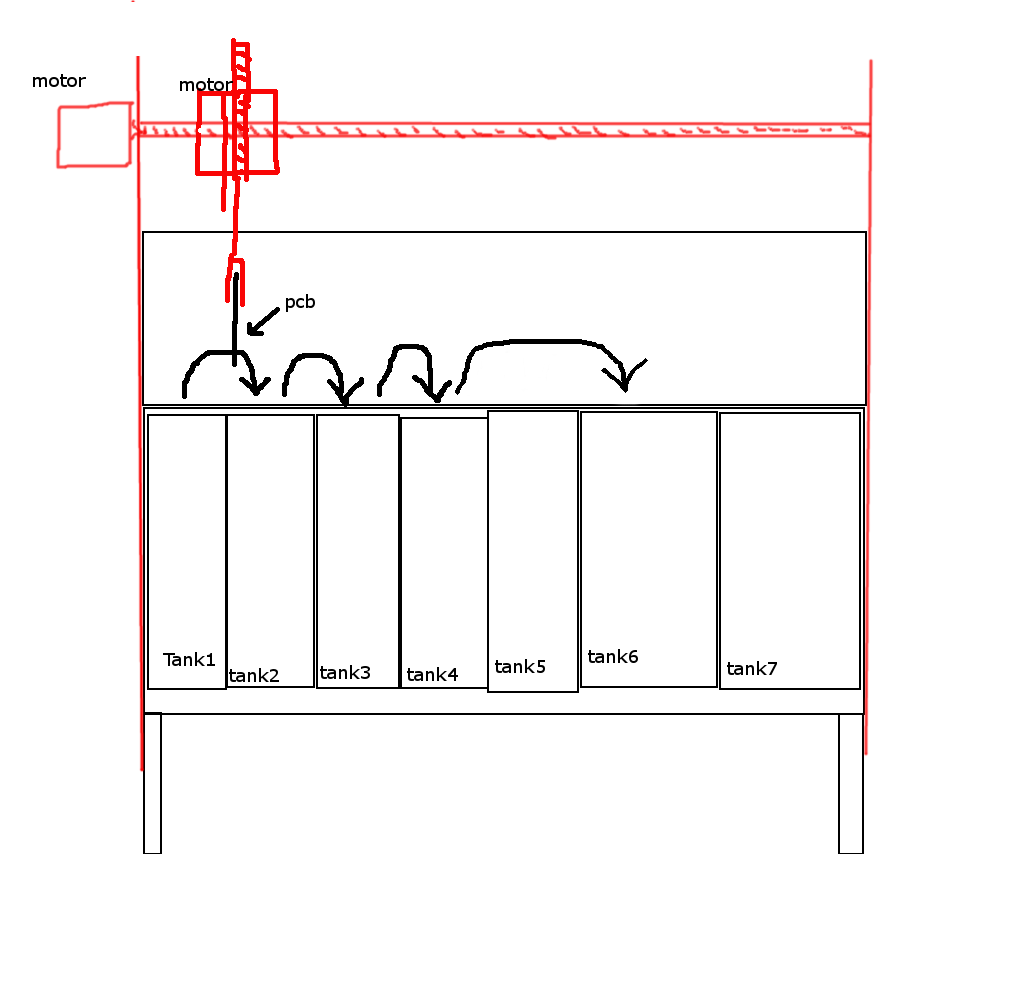
Here is the gimp image. Final Projects sketch.xcf
Second program was MyPaint, I was not sure if it needed a touch pad as the about section was talking about the touch when painting. But installing it to the laptop, it seemed to work fine. I am still not sure if it would work differently on touch pad device and I did not find it useful for me at the moment.
At the end I used some 3D programs to first sketch the project and after that used GIMP to sketch some sensor and motor positions on the 3D model. Here is the result of GIMP operation.
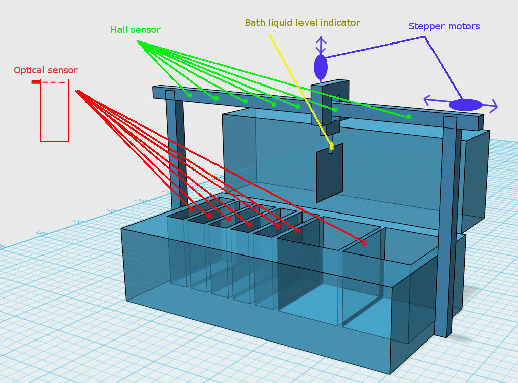
Here is the gimp image. 123D-hahmotelma_gimp.jpg
At the end I got used to some features that were done differently than in Photoshop, like activating layers to edit layer content. Otherwise I used general draw line and dot with a pencil or bruch tool -tools, and added some text with text tool.
3D tools
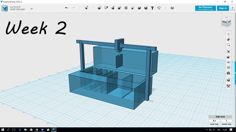
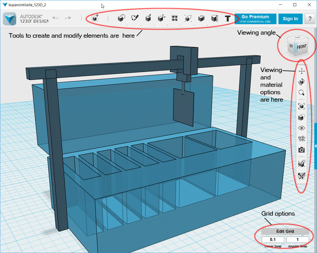
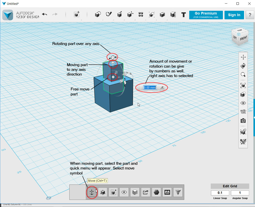
Next I downloaded 123D for testing 3D programs. Luckily we had a local fab lab tutorial session for 123D inkskape and Solid works, so I had some basics already. This is what basic 123D-working envinronment is build. On top of the screen are tools to create and edit new primitives, creating sketches and konstructing parts out of sketshes. Modification like boolean operations can be found there.
On the right are is the menu icons for viewing options and options for visualisation like using textures.
On the right top corner is a common 3D design environment viewing cube, that lets user easily change the viewing directions when needed. On the right bottom corner there is tool to edit grid options.
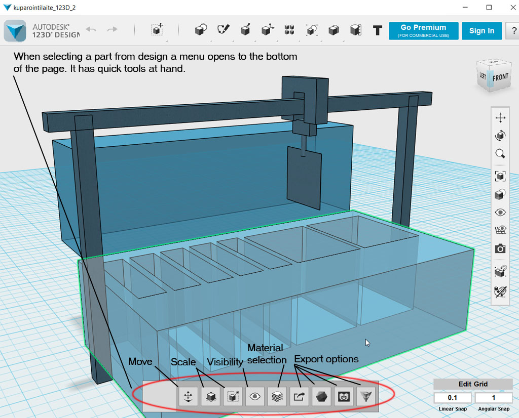
When part of the design is selected, there is a quick menu that will open at the bottom of the page. This has many common features quickly at hand. Especially when you want to move or re-orient a part, this is good way to go at it.
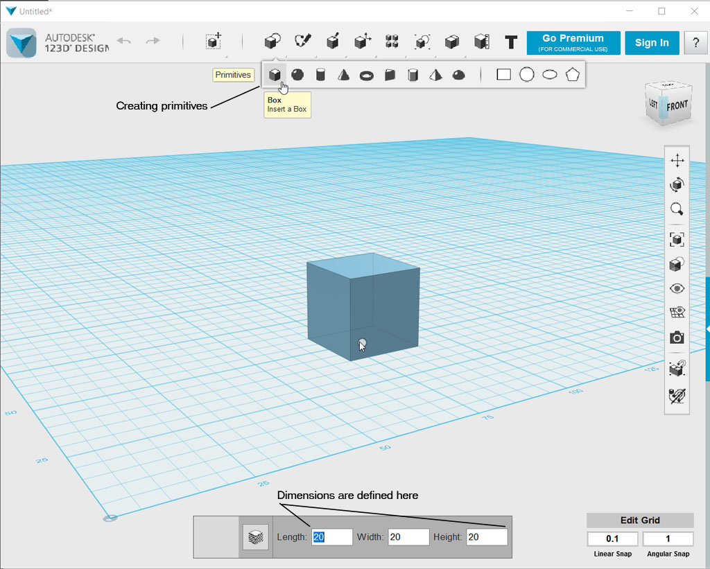
Designing the first sketch of my final project, I mainly used tools like create creating primitives.
Moving an object is done by selecting it and then using quick panel at the bottom of the screen. When moving is selected there is a orientation and direction indicating visualisation connected to the object at hand. Moving or rotating part is done by using that.
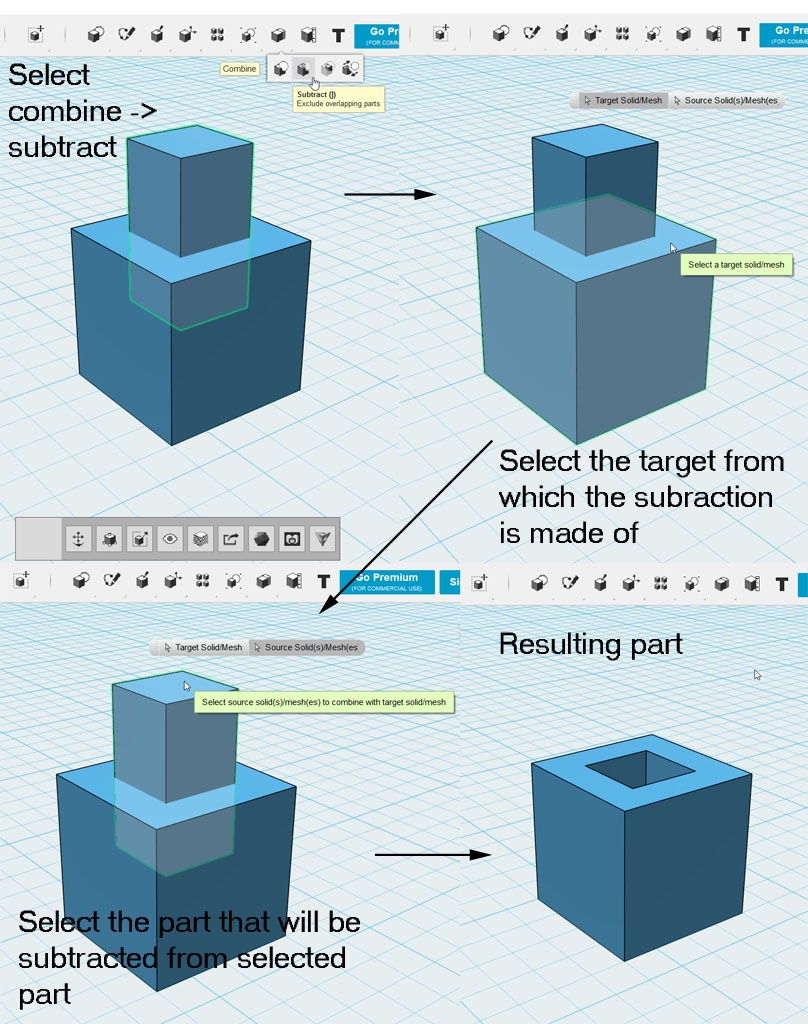
One tool that I used a lot is the boolean subtract. This I how I made the tanks to the final project sketch.
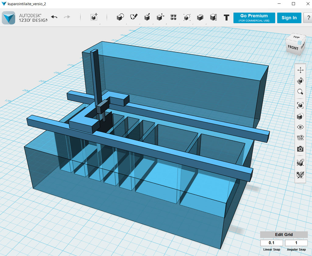
Using mostly these tools I created a model for my final project. The result of 123D program is here. It is the same model I used on GIMP example but from different angle. The darker part is the final project part, the blue one is the original process equipment.
In 123D I used a lot of different tools like: creating primitives (boxes mostly), used boolean operations that are named as Combine in 123D. Biggest problem with 123D was the orientation and positioning of the parts, as there is not any specific options for that. One just has to move them around with mouse and see from different angles what they are in correct place.
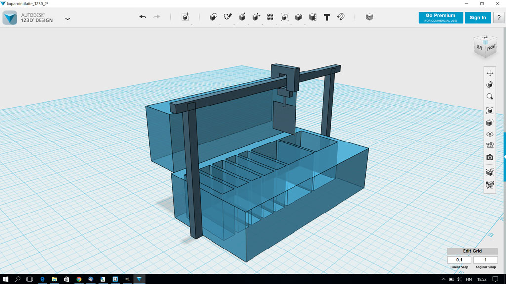
After having an interesting small chat with my co-student Mikko, I made this other possible version picture.
Here is the 123D file. Kelkka_versio2.123dx
Next I downloaded and installed FreeCAD. FreeCAD needs much more tutorial to get into with all the workbenches and their usage. But after viewing some tutorials on Youtube, I started to get into the idea how they work.
I used a mainly part and part design workbenches to make this 3D sketch of couple of the bath tanks and the blank pcb holder that we have now.

Files used with this weeks assignment
123D generated .dxf file kuparointilaite 1
123D generated .dxf file kuparointilaite 2
123D generated .123dx file kuparointilaite 1
123D generated .123dx file kuparointilaite 2
FreeCAD design .FCStd file