Making in-circuit programmer
Following the global lecture of the week, in our lab, we practiced creating Printed Circuit Boards (PCBs). Together with the instructors and peers, we went through steps to design Brian's version of PCB. We downloaded Brian's PNG files for the Traces and Outline Cutout which were used to set milling fabmodules.org. Due to the absence of experience with anything that has to do with PCBs, I proceeded with the same design and used the .rml files we created.
Thanks to the staff of our FabLab, we have excellent guides for operating the machines. For this week, milling and electronics and design production guides give an overview of how to use Roland SRM-20 available in our lab, as well as how to prepare files for milling.
According to the guides, first is important to prepare necessary materials: the stock and the milling bits. We have both FR1 (suitable for manual soldering only) and FR4 (suitable to be used in the reflow oven) stocks available, however, for the FabAcademy assignments we use primarily the FR1. Recommended milling bits are 1/64 inch (0.4mm) for milling traces and 1/32 inch (0.79mm) for cutouts. We have been successfully using a 0.2-0.5mm milling bit for the traces and a 1.00mm one for the cutouts.
After the materials are ready:
- Use .png files to create .rml files in fabmodules.org (see details below)
- Prepare the stock for milling: make sure it's clean and flat
- Tightly attach the stock to the wooden base of the milling machine with the double-sided tape
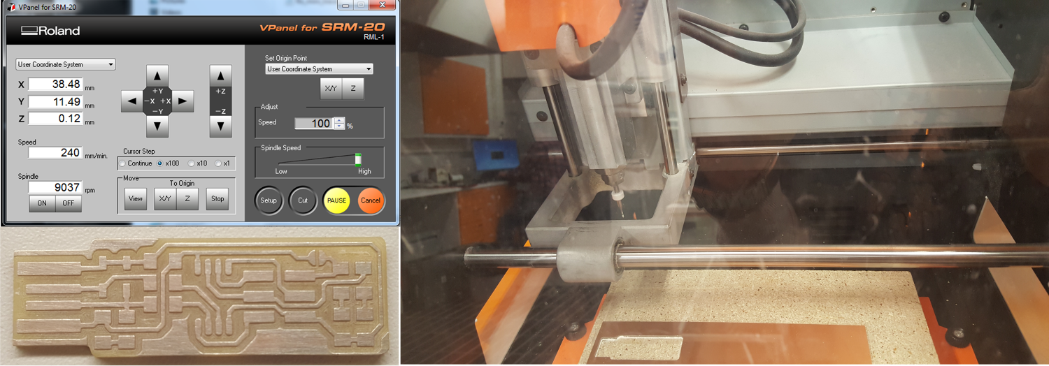
- Set up the milling machine (Roland monofab SRM-20) and the software (VPanel SRM-20) for milling
- Set X/Y (left bottom by default) and Z origins.
- To set the X/Y use arrows in VPanel
- To set the Z, first carefully lower the milling bit as close to the stock surface as possible with the VPanel's arrow button. Then, with the screwdriver/hex key/Allen wrench loosen the milling bit, so it lowers down to the surface. Tighten the milling bit again.
- Import .rml trace file to mill. Choose Cut - Delete old files - Add the traces .rml file - Output (milling starts immediately!)
- When traces are milled, clean out the milled dust
- CHANGE the milling bit for cutout and readjust the Z origin. DON'T readjust X/Y origin. Import .rml cutout files
- When the cutout is milled, clean out milled dust
- Take out your board. A screwdriver or a knife work. Either to be handled with caution
- Be nice: clean out the area and put tools where they belong
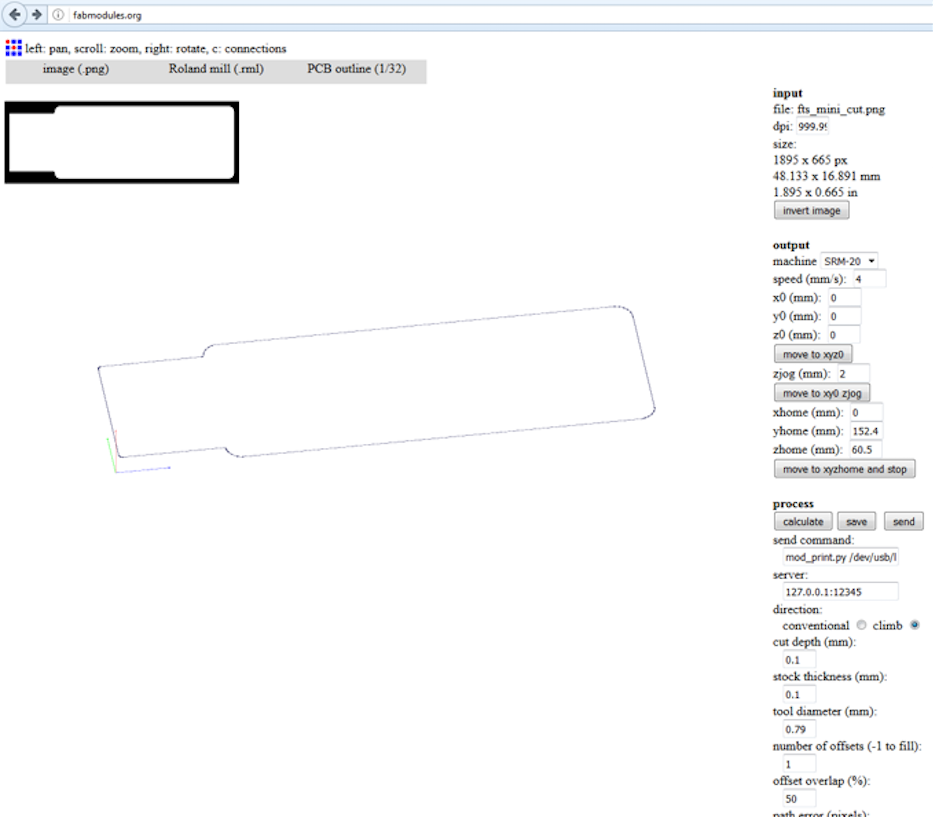
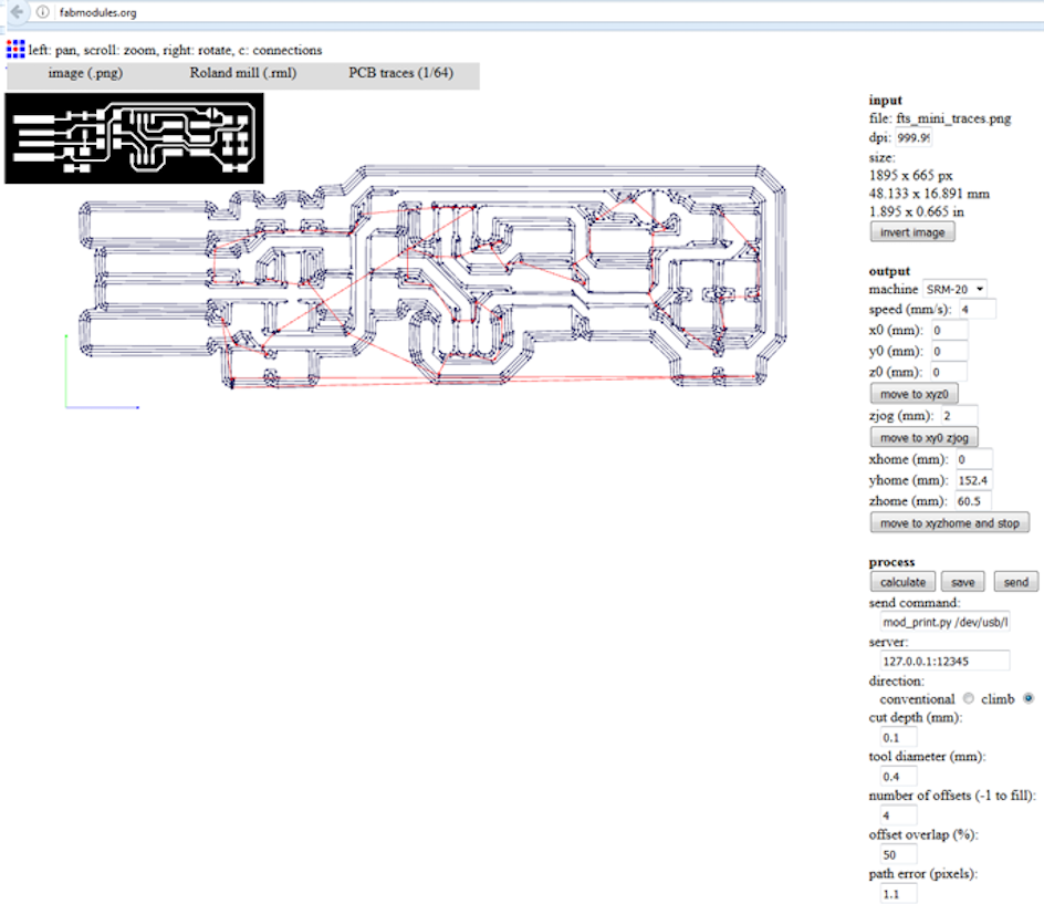
To prepare .rml files for traces and cutout in fabmodules.org
- Input format: image (.png) file of traces or cutout to be milled
- Output format: Roland mill (.rml)
- Process: PCB outline (1/32 inch) or PCB traces (1/64 inch) for cutout and traces respectively.
- Set milling parameters
- For both traces and cutout choose machine SRM-20 and set x, y, and z to 0, set the size of milling bit (0.2-0.5mm for the traces and 0.79-1.00 for the cutout) and cut depth (recommended value for traces is 0.1-0.15mm and for the cutout is 0.5mm)
- For the cutout also set stock thickness (1.7mm to 1.75mm depending on the stock)
- Calculate and Save
Milling went fine: with the help of instructors I was able to set the hardware and softwaree parameters on correctly, so the traces came out well. There were just a few tiny ones I had to remove with a scalpel. For milling the Roland SRM-20 machine and Software VPanel for SRM-20 were used.
Next I found components required by the design
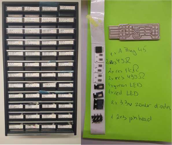
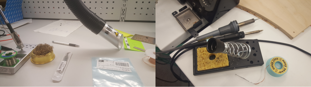
As I have never done any soldering before, I spent some time practicing soldering and desoldering random components to/from random PCBs. Thanks to Jari for volunteering giving a "Soldering for Dummies" tutorial and providing random PCBs. I tried several soldering guns available in the lab to find the one which seems to be the easiest to use for this week's assignment.
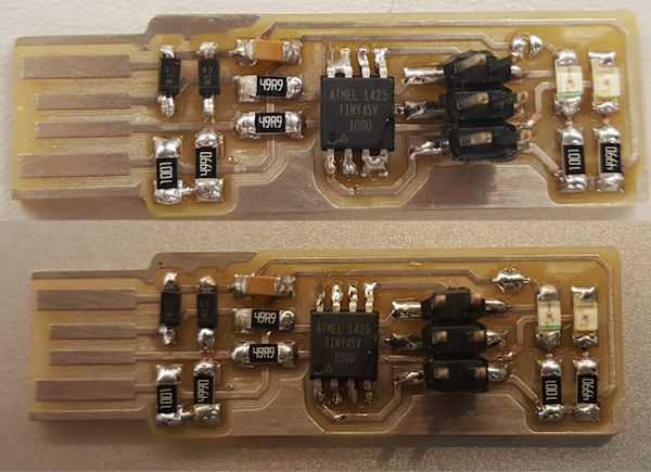
Following Brian's recommendations, I checked what is the correct orientation for installing the microprocessor, diodes, LEDs and the capacitor. Although still far from getting soldering job perfectly, I am quite happy with the final outcome I managed to achive. No damage done to my PCB, the compoments, myself or peers in the lab. Initially, I did make a few mess-ups having too much solder, which I managed to correct relatively quickly and effectively cleaning out the excessive amount with the desoldering braid.
Programming
I used with the instructions for programming on Windows 10 on Brian's page. I followed these steps:
- Using the GNU AVR toolchain on Windows 10
- Git Installation
- Atmel GNU Toolchain Installation
- GNU Make Installation
- avrdude Installation
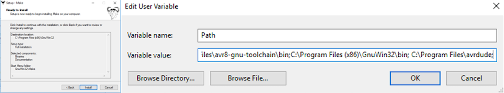
- PATH Update
Start - Control Panel - System - Advanced System Settings - Advanced - Environment Variables
User variables - Path - Edit OR New - Path
If a list input is available add
    C:\Program Files\avr8-gnu-toolchain\bin

C:\Program Files (x86)\GnuWin32\bin


C:\Program Files\avrdude
Otherwise, enter values separating with a semicolon in a textbox - Downloading Zadig to install drivers for programmer
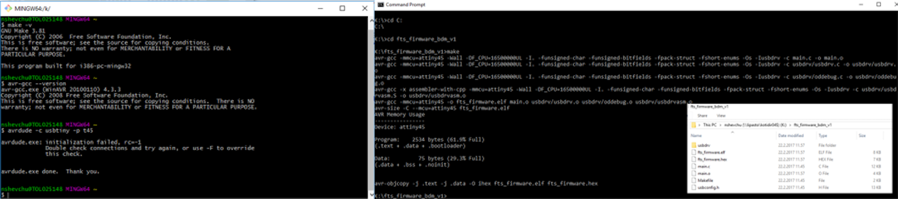
- Checking in Git Bash commands make, avr-gcc, and avrdude work fine
- In the menu search for Git Bash and start it
make -v+ Enter should return the following (or similar):
GNU Make 3.81

    Copyright (C) 2006 Free Software Foundation, Inc.
...
Ifcommand not foundis shown instead, re-checking of installation of make and the path variable setting for typos is requiredavr-gcc --version+ Enter should return the following (or similar):
avr-gcc.exe (AVR_8_bit_GNU_Toolchain_3.5.4_1709) 4.9.2
...
Ifcommand not foundis shown instead, re-checking of installation of the Atmel toolchain and the path variable setting for typos is required.- Connect the programmer to a USB port
avrdude -c usbtiny -p t45+ Enter should return the following:
avrdude.exe: initialization failed, rc=-1
...
This means that avrdude successfully found the programmer, but failed to talk to a target board (because nothing is connected to the programmer)
If insteadavrdude.exe: Error: Could not find USBtiny device (0x1781/0xc9f)is shown, USB driver installation (the Zadig steps) needs to be checked.
Ifcommand not foundis shown, checking the installation of avrdude and the path variable is required - Downloading the firmware source code, unzipping the file, and opening Command Prompt, and cd navigating cd into the source code directory (K:/fts_firmware_bdm_v1). After running make, file fts_firmware.hex was created
- Using FABISP programmer provided by the local instructor Jani, did not require making changes to the Makefile
- Connecting the programmer to the computer with the USB hub and to my PCB
- Running commands make flash, make fuses
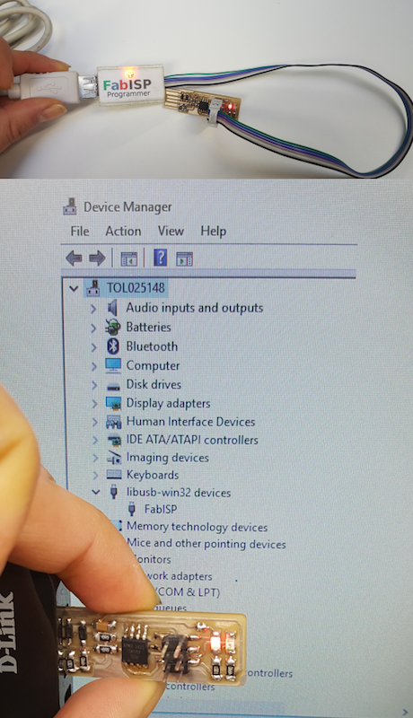
- After disconnecting the FABISP, I connected my PCB, which showed up in the Device Manager (Start → Control Panel → System → Device Manager)
- Reconnecting the FABISP programmer and running make rstdisbl
I still need to remove solder from the jumper to break the connection and tested the programmer to program another board to make sure my PCB was programmed correctly.
Files:
Roland Milling Files
Remember, remember...
- When soldering, best to start with the most difficult parts (the ATtiny45 in my case) and finish with the pin header last, as it can get in the way if soldered earlier.
- Make sure to apply the right amount of solder: solder connections should be smooth with solder both onto the pin and onto the pad, yet excess solder is to be avoide as it creates unwanted solder bridges between nearby traces and pins
- Get the assignments done the week they are assigned. Any carry-over will most likely bite.