- what will it do?
- who's done what beforehand?
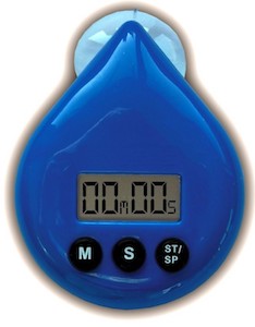
- Ecosaver Shower Timer
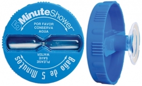
- Culver Shower Timer
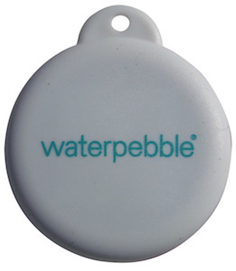
- Water Pebble
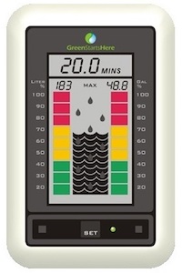
- Greenstartshere Shower Saver
- Renergise shower timer
- what materials and components will be required?
- where will they come from?
- how much will it cost?
- what parts and systems will be made?
- what processes will be used?
- Project management has been used for documentation and completing parts of the final assignment in a timely manner
- Computer-aided 2D design is used for creating a box for all electronics and for making a vinyl cut sticker design
- Computer-aided 3D design to make the support
- Computer-controlled cutting for lasercutting the box and and vinylcutting the sticker
- Electronics design and production (creating schematic and board layouts in Eagle, generating milling files in fabmodules, milling stuffing and soldering PCBs) for making the boards
- Embedded programming for programming the boards
- Working with input and output devices (LCD screen, electret microphone, LED lights, Piezo)
- Embedded Networking to create the serial network
- what tasks need to be completed?
- what questions need to be answered?
- What is the optimal way to put together all the parts?
- How to minimaze the size of the device?
- What can help synchronizing the processes?
- what is the schedule?
- By June 3rd: designing/making a board with the LEDs and the power-on switch, making an LCD board, making wiring
- By June 7th: Programing the boards, design the casing
- By June 10th: Assembling the device
- June 10-13th: final troubleshooting + making the presentation
- June 14th: Presentation
- How will it be evaluated?
It will be a device aiming to help the user decrease water consumption by giving an alarm when the user is running water for more than a certain period of time.
There are several commercial products that carry out a similar function. I have not found any similar projects in Fabacademy. Some examples of devices available on the market:
4 PCBs (switch-on, sound sensor, LCD, piezo), wires for connecting the PCBs, 9V battery, ISP programmer, FTDI cable for debugging and/or possible user interfacing, acrylic plastic for the external case.
All of the components will come from the Fablab inventory.
Switch-On Board (microprocessor ATTINY44A-SSU-ND,
FTDI connector,
20MHz resonator,
slide switch,
1uF capacitor * 2,
10K Ohm resistor * 2,
499 Ohm resistor * 3,
2X2 pinheader,
2X3 pinheader * 2,
LED * 3
);
Sound Sensor Board (microprocessor ATTINY44A-SSU-ND,
electret microphone 668-1296-ND, , Op-Amp AD8605ARTZREEL7CT-ND,
Regulator LM3480IM3-5.0/NOPBCT-ND,
LED, 1uF capacitors * 4,
10k Ohm resistors * 5,
1k Ohm resistor,
499 Ohm resistors,
2X3 pinheader,
2X2 pinheaders * 2);
LCD Board (microprocessor ATTINY44A-SSU-ND,
2X2 pinheader * 2,
2X3 pinheader,
2X5 pinheader,
20MHz resonator,
LCD screen,
5V regulator,
1uF capacitor,
100nF capacitor,
1K Ohm resistor,
10K Ohm resistor,
100K Ohm resistor);
Piezo Board (microprocessor ATtiny45,
piezo buzzer,
4.7V zener diode,
2X2 pinheader,
2X3 pinheader,
1M Ohm resistor);
Bridge Board
2X2 pinheader, microprocessor ATtiny45, 1uF capacitor, 499 Ohm resistor, 1K Ohm resistor, LED, FTDI pinheader.
PCB stock, FTDI cable, connecting wires, connectors, 9V battery, acrylic plastic.
| Component | Quantity | Cost/Unit | Total |
|---|---|---|---|
| microcontroller ATTINY44A-SSU-ND | 3 | 1.18 | 3.54 |
| microcontroller ATTINY45V-10SU-ND | 2 | 1.23 | 2.46 |
| resonator 20.00MHZ SMD | 2 | 0.43 | 0.86 |
| zener diode 4.7 | 1 | 0.07 | 0.07 |
| electret microphone 668-1296-ND | 1 | 1.65 | 1.65 |
| op-amp AD8605ARTZREEL7CT-ND | 1 | 1.35 | 1.35 |
| regulator LM3480IM3-5.0/NOPBCT-ND | 2 | 0.32 | 0.64 |
| 1uF capacitor | 8 | 0.07 | 0.56 |
| 100nF capacitor | 1 | 0.12 | 0.12 |
| resistor 499 Ohm |
5 | 0.01 | 0.05 |
| resistor 10K Ohm | 9 | 0.01 | 0.09 |
| resistor 100K Ohm | 1 | 0.01 | 0.01 |
| resistor 1K Ohm | 2 | 0.01 | 0.02 |
| resistor 1M Ohm | 1 | 0.01 | 0.01 |
| LED Orange | 2 | 0.1 | 0.2 |
| LED Red | 1 | 0.13 | 0.13 |
| LED Green | 1 | 0.15 | 0.15 |
| LCD 16X2 module | 1 | 7.06 | 7.06 |
| Piezo | 1 | 2.95 | 2.95 |
| 2X2 Pin Header | 7 | 0.66 | 4.62 |
| 2X3 Pin Header | 5 | 0.6 | 3 |
| 2X5 Pin Header | 2 | 0.67 | 1.34 |
| 9V battery | 1 | 4.88 | 4.88 |
| 9V battery snap with 2pc molded | 1 | 0.52 | 0.52 |
| 5V FTDI cable | 1 | 20 | 20 |
| 2X2 connector socket | 7 | 0.55 | 2.75 |
| 2X5 connector socket | 1 | 0.55 | 0.55 |
| Tin power socket crimp | 8 | 0.05 | 0.4 |
| Plastic crimp connectors | 8 | 0.05 | 0.4 |
| Other (acrylic plastic, material for 3D printing, PCB stock, solder, ribbon cable, heatshrink tubing for insulation) | n/a | n/a | n/a | Total | 60.38 USD |
Five boards, each carrying out a certain function will be joined via serial network to make an integrated system. When one board senses sound, timing starts, green LED will be on and the LCD screen will start showing the time. When half of the programmed time elapses, the second LED will switch on and the Piezo will buzz, and when the all time elapses, the red light will switch on and and the Piezo will buzz again.
The project covers a wide reange of skills asquired in the course.
Establishing networking, assembling the device, testing and debugging.
The succcessful project should incorporate all planned processes. Each of the processes should be executed flawlessly on its own as well as integrated in the sequence with the other processes. Important success factors are precision of the sound sensor, and timing of the messages on the LCD screen, LED light signals and the piezo buzzer.
This is an individual project.
Noted.
Remember, remember...
- Do your best planning, because you WILL run out of time...