Designing the Board
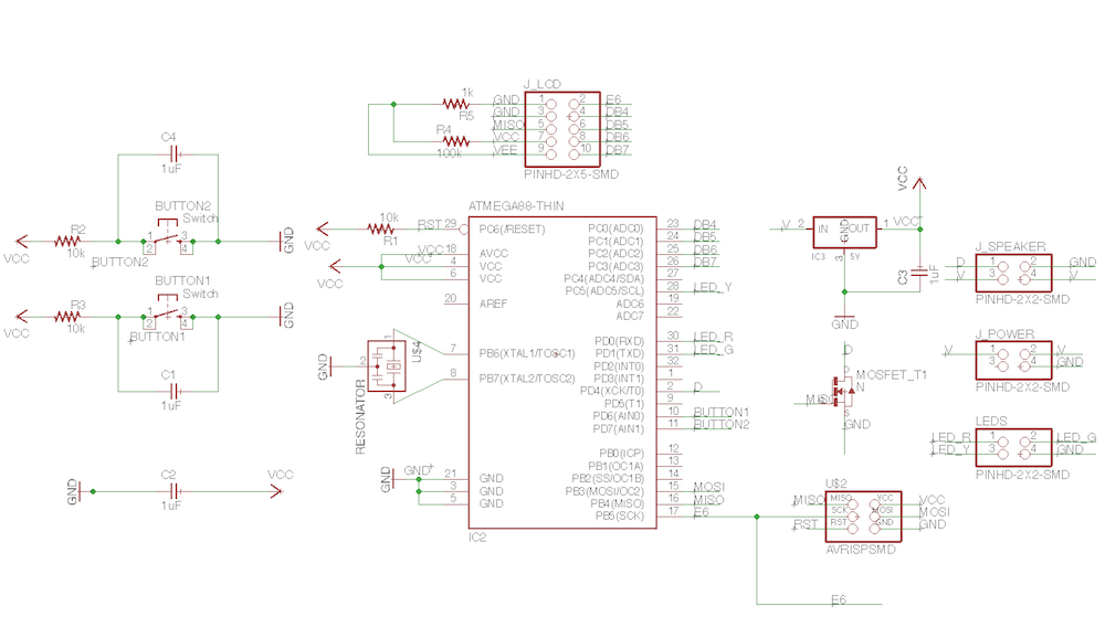
The initial plan for this week was to design the DreamBoardWeek10 board that I can use in my final project. Seem like this board will need the following components:
I was not able to make a one sided board design, so I decided to try shifting buttons with their capacitors and resistors to the board with the LEDs.
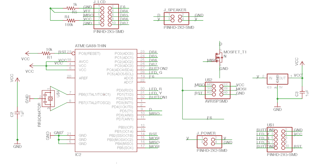
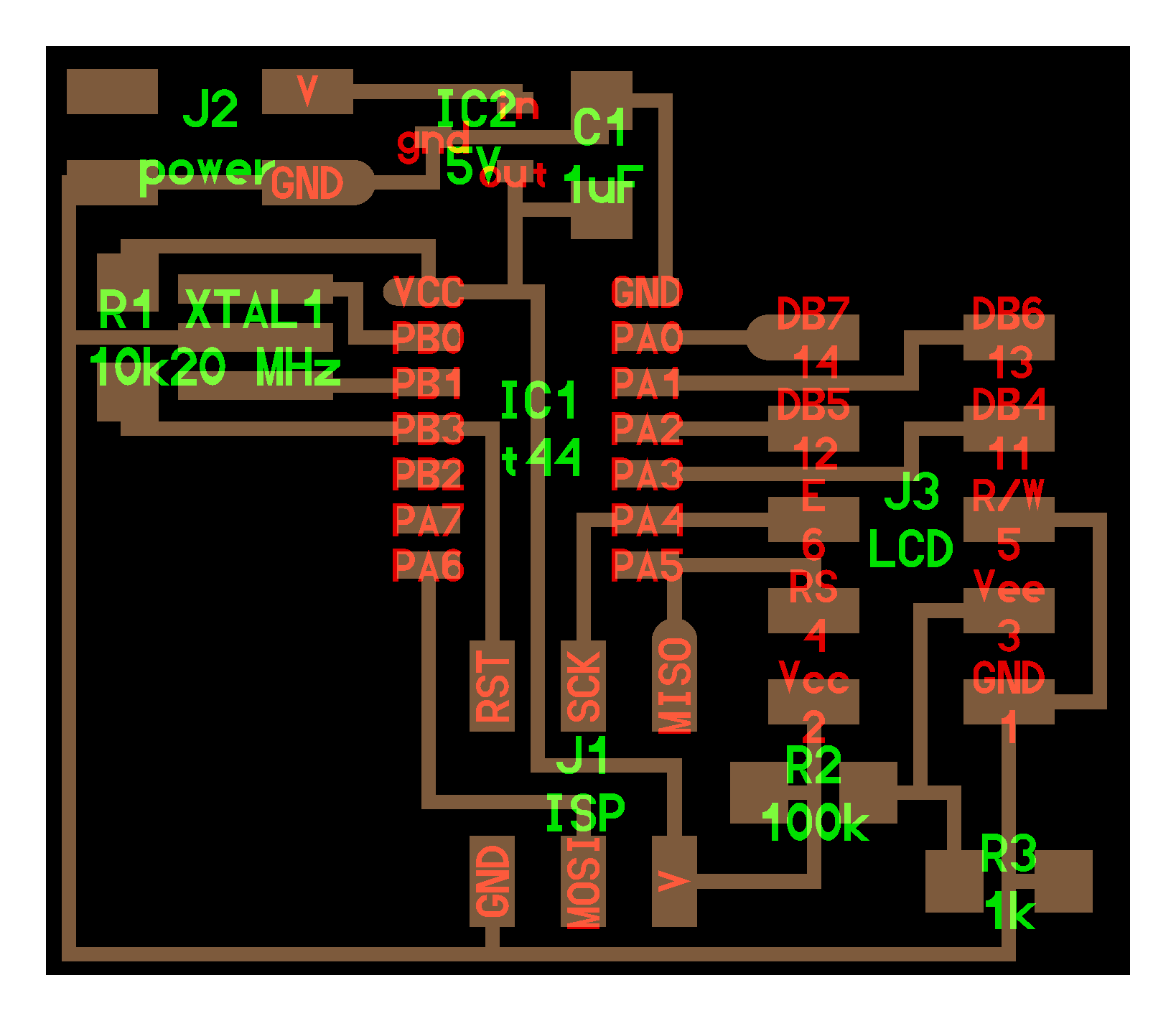
As it turned out, the board with fewer components was not much easir to design in the given timeframe. So DreamBoardWeek10 did not come true. I settled with a decision to make Neil's hello.LCD board with a slightly modified design ending up with the AlternativeDreamBoardWeek10. Components on this board are:
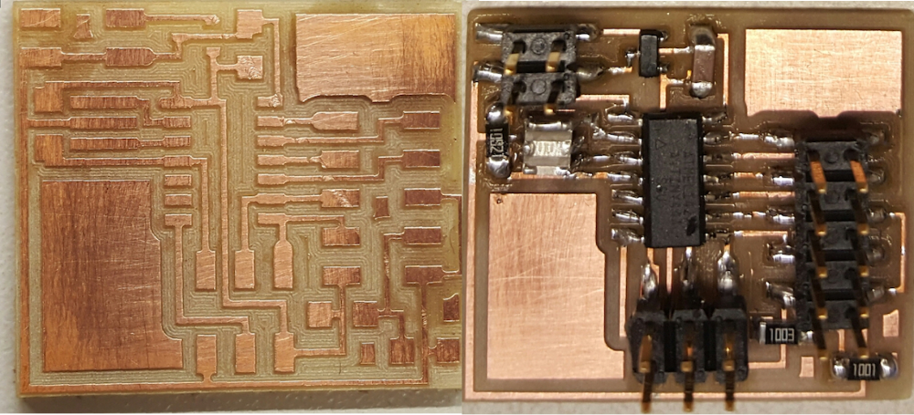
Producing the Board
When I started milling this week I used a wrong milling bit, so the traces were not milled properly on the FR1 .062 circuit board stock with the Roland SRM-20 milling machine.
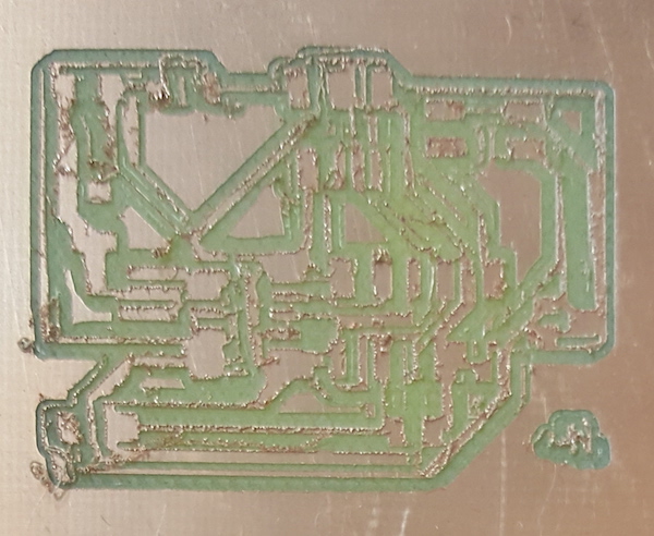
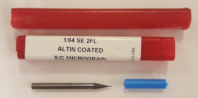
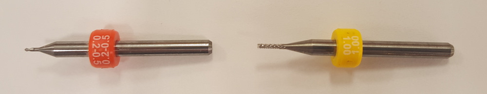
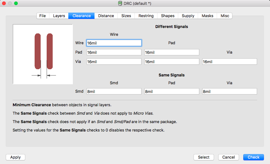
Next time with the correct milling bit the traces did not come out right because of the 8mil Clearance setting in the Design rules in Eagle.
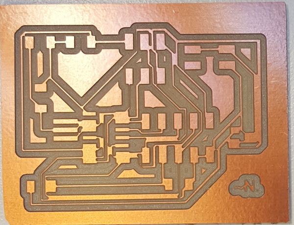
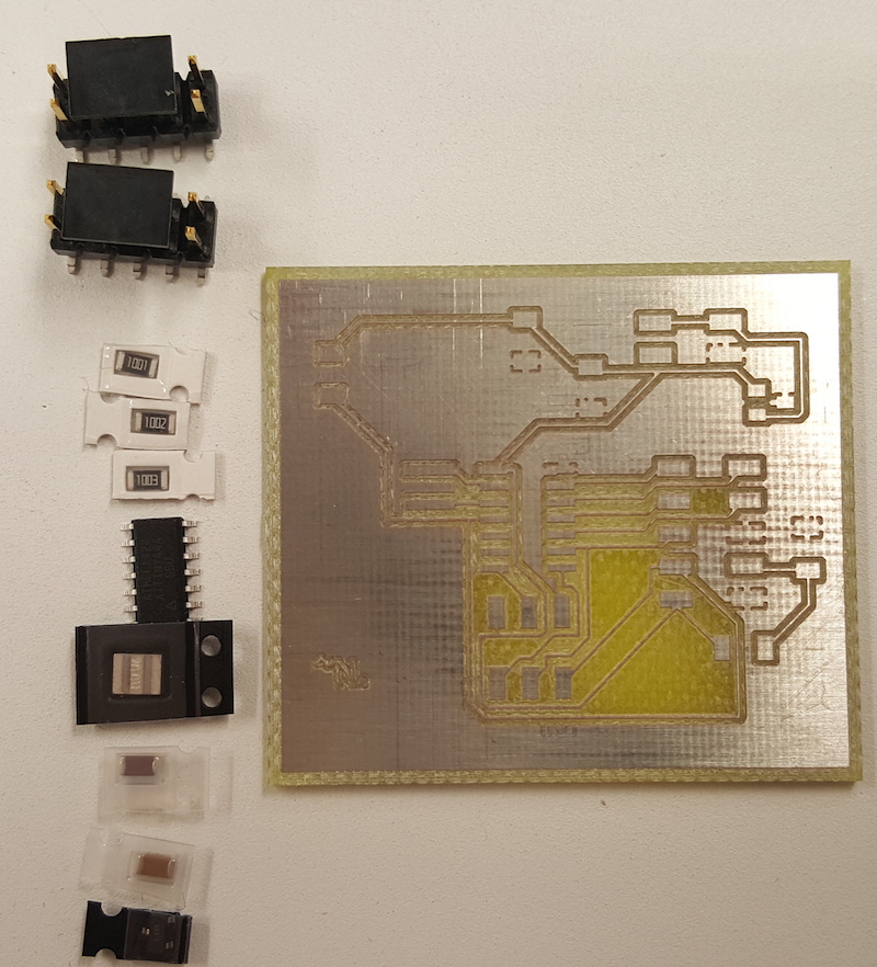
I had to modify the design once again to adjust the Clearance setting to 16mil. Due to lack of time, I ended up milling this board on FR4 with < a href="http://www.lpkf.com/products/rapid-pcb-prototyping/circuit-board-plotter/protomat-s103.htm">ProtoMat S103 used for professional PCB milling.
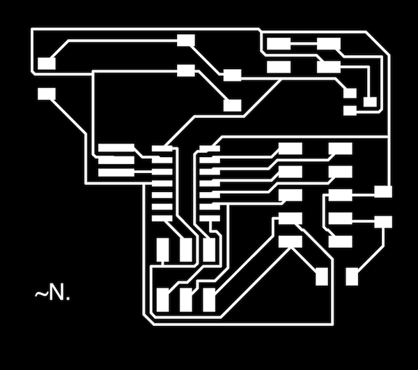
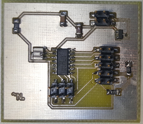
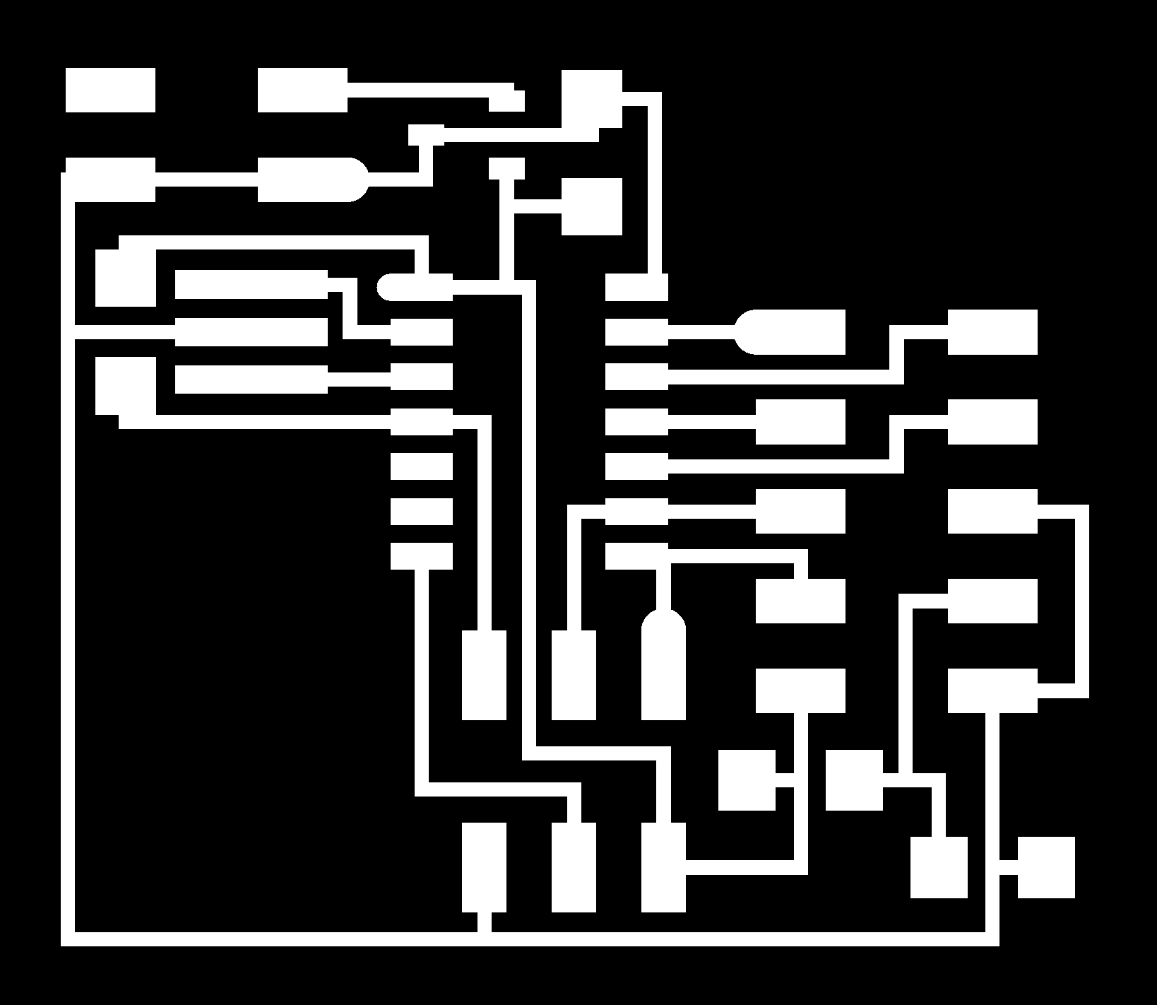
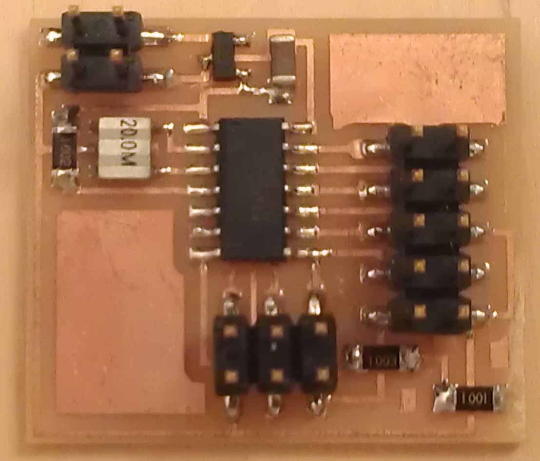
I recreated the traces, milled and stuffed this board, the AlternativeDreamBoardWeek10 V2.
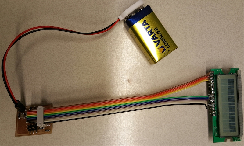
Connecting LCD
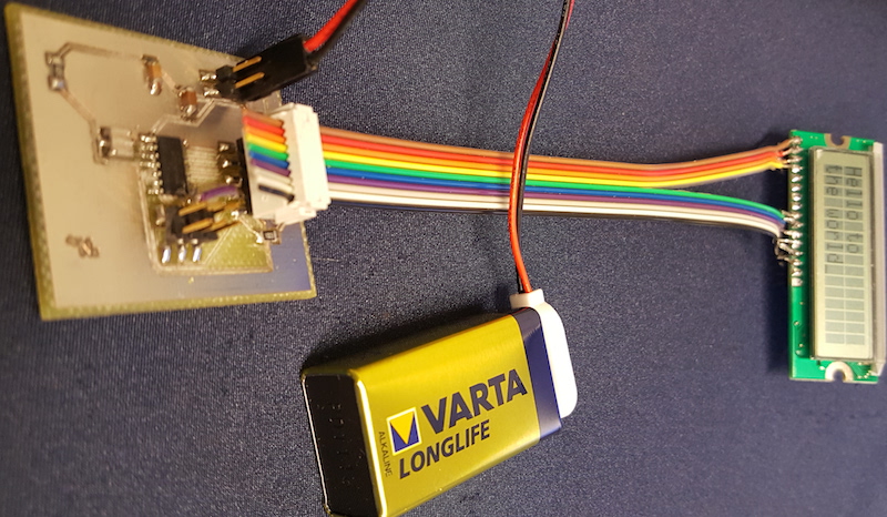
I checked the LCD datasheet to match the right pins. To connect the LCD to the board, I used a split rainbow cable. The insulation is taken off of the cables' ends which are soldered to the pin soldered to the LCD.
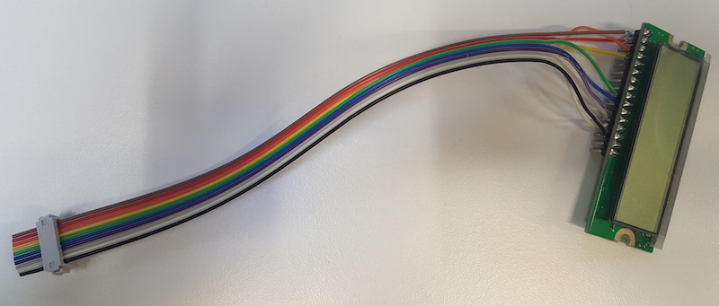
Initially, when I tried powering the board with a 9V battery, the screen lit up.
Programming the Board
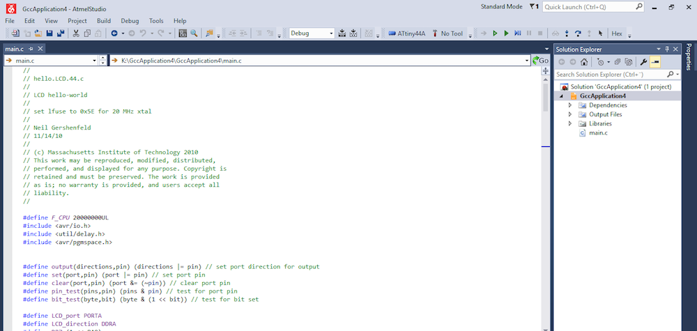
I connected the ISP programmer to the board and used Atmel Studio to attempt programming the board.
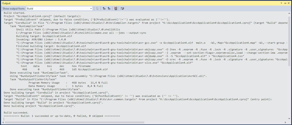
After I added #define F_CPU 20000000UL, I successfully compiled Neil's hello.LCD.44 code for a board with the LCD screen.
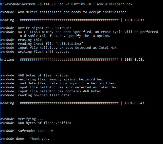
Then I used avrdude in Windows command line (cmd.exe) to program ATtiny44A, using a .hex file created in Atmel Studio.
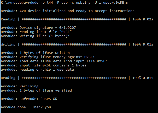
There was no output on the screen. When later I attempted debugging, I ran into hardware issues. The screen was occasionally lighting up when connected to power. Even during the recitation time, I was still trying to figure out what the problem is and how to fix it and proceed with finishing programming...
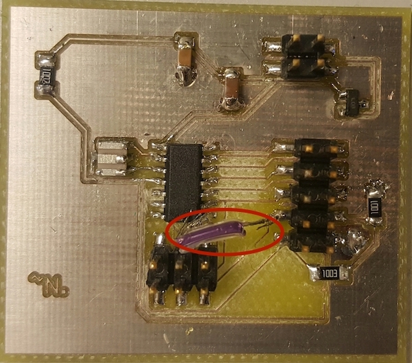
Later on, thanks to Jari, the problem was discovered: my schematic had an error. Instead of connecting one of the LCD pins to MISO, I attached it to RST.
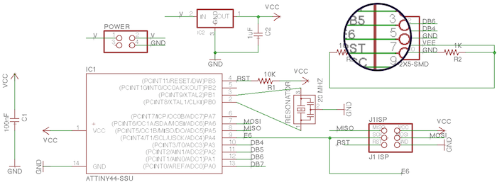
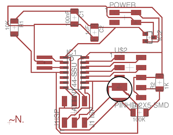
NOTE:I made the same mistake in both of my DreamBoardWeek10 and AlternativeDreamBoardWeek10 boards, so the attached .brd and .sch Eagle files contain this error. For sure, elimitating this discrepancy is on the to-do list for the final project.
After fixing the connection, the LCD greeted the world :)
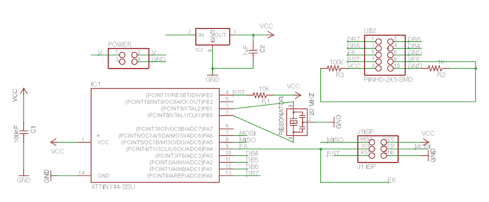
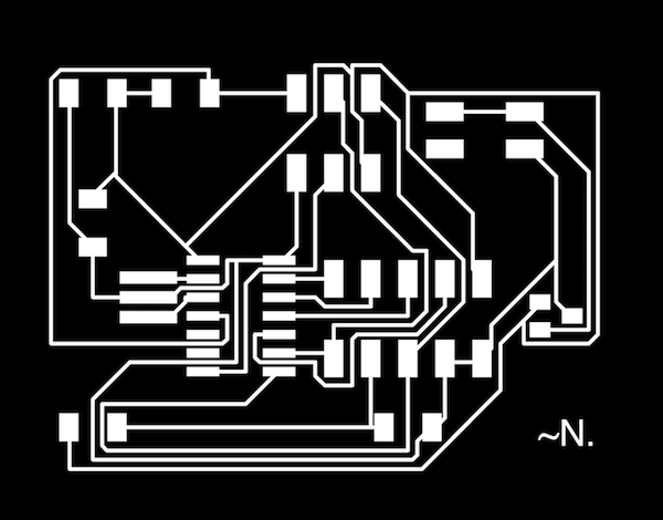
Simulteneously with fixing my board, I tried to complete the weekly assignment by replicating Neil's hello.LCD.44 board. I used the traces and interior files provided in our schedule to mill the board and the board layout and components as a reference. The board was milled on FR1 with Rolland Monofab SRM-20.
Although I was able to program the board using the .hex file created earlier, the code didn't work.
Together with my peers, I spent a while trying to find out what the issue is, but haven't had any luck yet. If I have time, I'd like to find out the problem and fix it.
Files:
Layouts and schematics of the dream boards and the one that was milled and stuffed, .c add .hex files used for programming.