Mechanical Design
Team
Introduction
This week we have to design a machine and this will be a group project. Machine action is tested mechanically and we have to automate it in coming week(Machine Design). We spend lot of time looking for good ideas. Some of the ideas we finalised are listed below. We have to choose one among them.
Project Criteria
As I said above, we had lots of ideas :). We filtered them using the criterias below.
- 1. Project should contain both mechanical as well as electronic parts.
- 2. Project should contain minimum 2 axis movements
- 3. Feasible with our constraints.
Some of the Ideas
We were confused about which idea to choose. Briefing some of the initial ideas.
1. PLAbot :
This is the first idea we had. We are using PLA material for 3-D printing and the wastage of the material is very high. Ultimaker machine stops most of the time and lots of material is wasted. We wanted to do recyle the wasted materials. The wasted materials can be collected together and then processed to build the filament for further printing.
Challenges :
When we looked into the feasibility we found that the high temperature used for heating the material can make the material lose its properties. It may also cause bubbles inside filament if proper care is not taken.
2. EdgeBander :
The models made of plywood and wood in the Lab lack quality finishing. Tables and chairs should look better if we could bind nice bands on edges. The edges are pretty sharp. So we thought of making a "EdgeBander" which will have two motors that will be moved along the opposite edges of the plywood and the banding materials will be binded along the edges.
Challenges :This will not meet the project criteria as it has only one degree of movement which is rotational motion along the horizontal plane.
3. SolarTracker :
This is something we almost fixed. SolarTracker as the name suggests tracks the motion of the Sun along its movement through the day to power something - like lighting using solar power. A solar panel is kept connected to a stepper motor which rotates 360 degrees. After one complete rotation the panel will go to the postion where maximum voltage(sunlight) is available. This process can be set to rotate every half hour to check the voltage. We were planning to use solar energy to power something here in the lab.
Challenges :Constant checking along 2 axis (azimuth and elevation angle) is something that is difficult. Also solar panels are costlier as well.
4. ZenithScope / Celestial Tracker(Name might change :P ) :
This is 'goto' telescope. It means, this telescope can point towards a planet when we feed its coordinates as input.
Challenges :Building good quality telescope :)
Feascibility Study and Project Selection
After discussion we all agreed to select 'Zenithscope' as our project. This is pretty interesting project. We were confused sometimes. We decided to build a build a small telescope for time being and concentrate more on the 'go-to' system. We will be developing good telescope as well, if time permits.
After going through a lot of material online, and understanding our constraints, we set the planned scope of our project.
- Default Position
- Auto-Locate Celestial Body
- Automated Movements of the telescope
- If possible, remote Controlled Movements.
Some interesting and inspirational videos we found online are below.
Assigning Tasks
Assigning tasks properly, was difficult. Anyway, some of us are good at mechanical side and some are good with programming side. So we decided split team the same way.
| Mechanical Design | Tanvir and Lancy |
| Electronic Design and Programing | Suhail, Siraj sir and Aneesh |
| Final assembly | Ofcourse, All together :-D |
Design and development
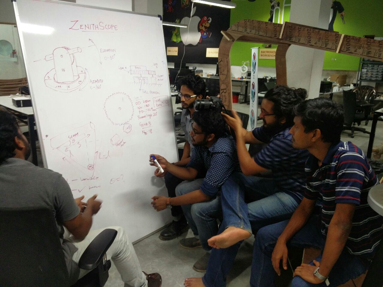
None of us have much astronomical knowledge. So, there is a lot we have to learn. We first discussed about the mechanical design. We came up with different ideas for holding telescope, moving telescope on horizontal & vertical axis, placing stepper motors etc.
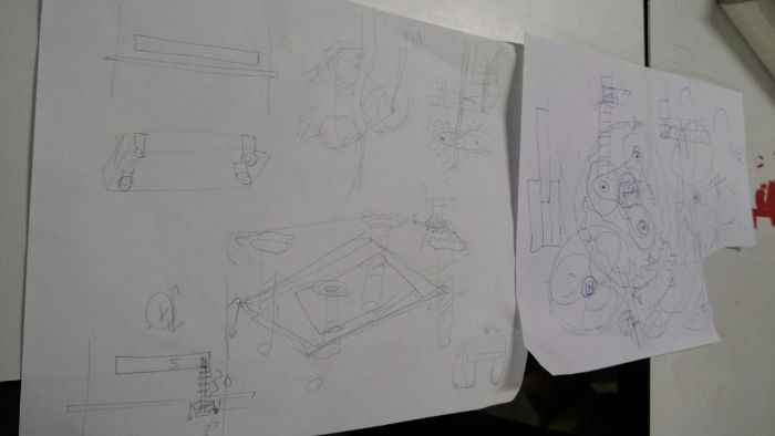
Sorry about above image. It was very late night drawings :)
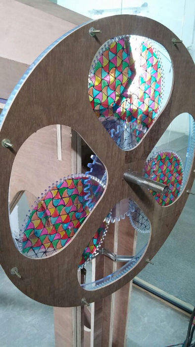
For reducing the gear ratio, and for the pun of it, we thought about incorporating a planetary gear system.
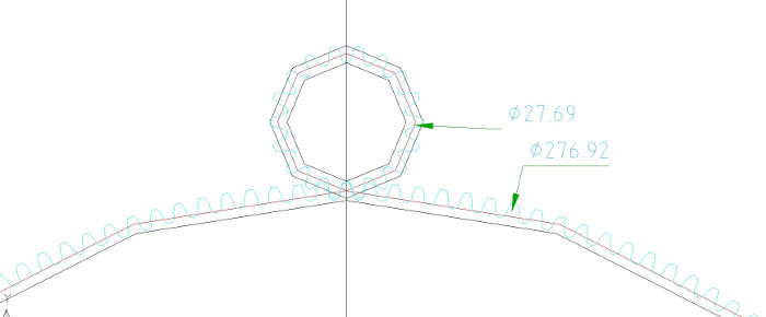
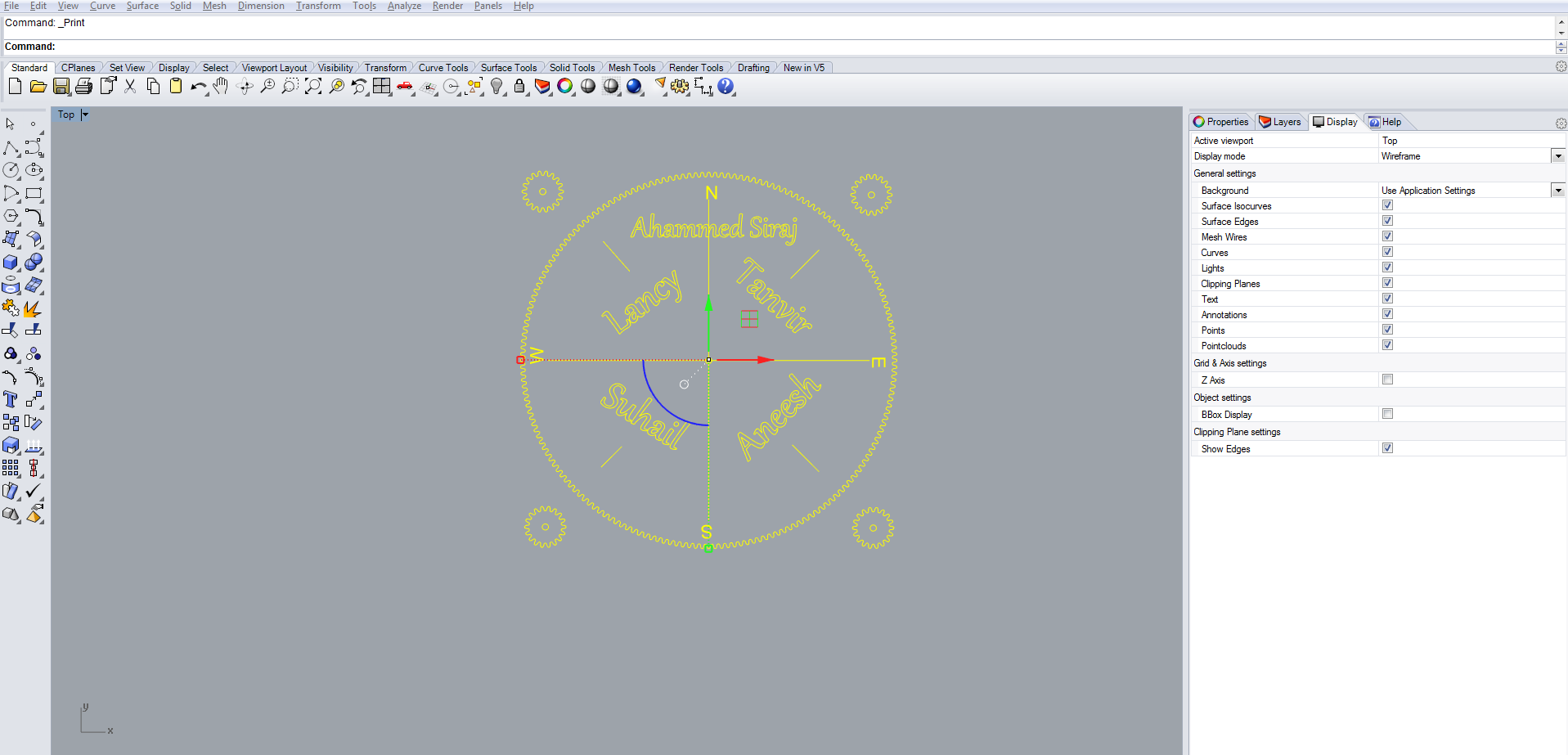
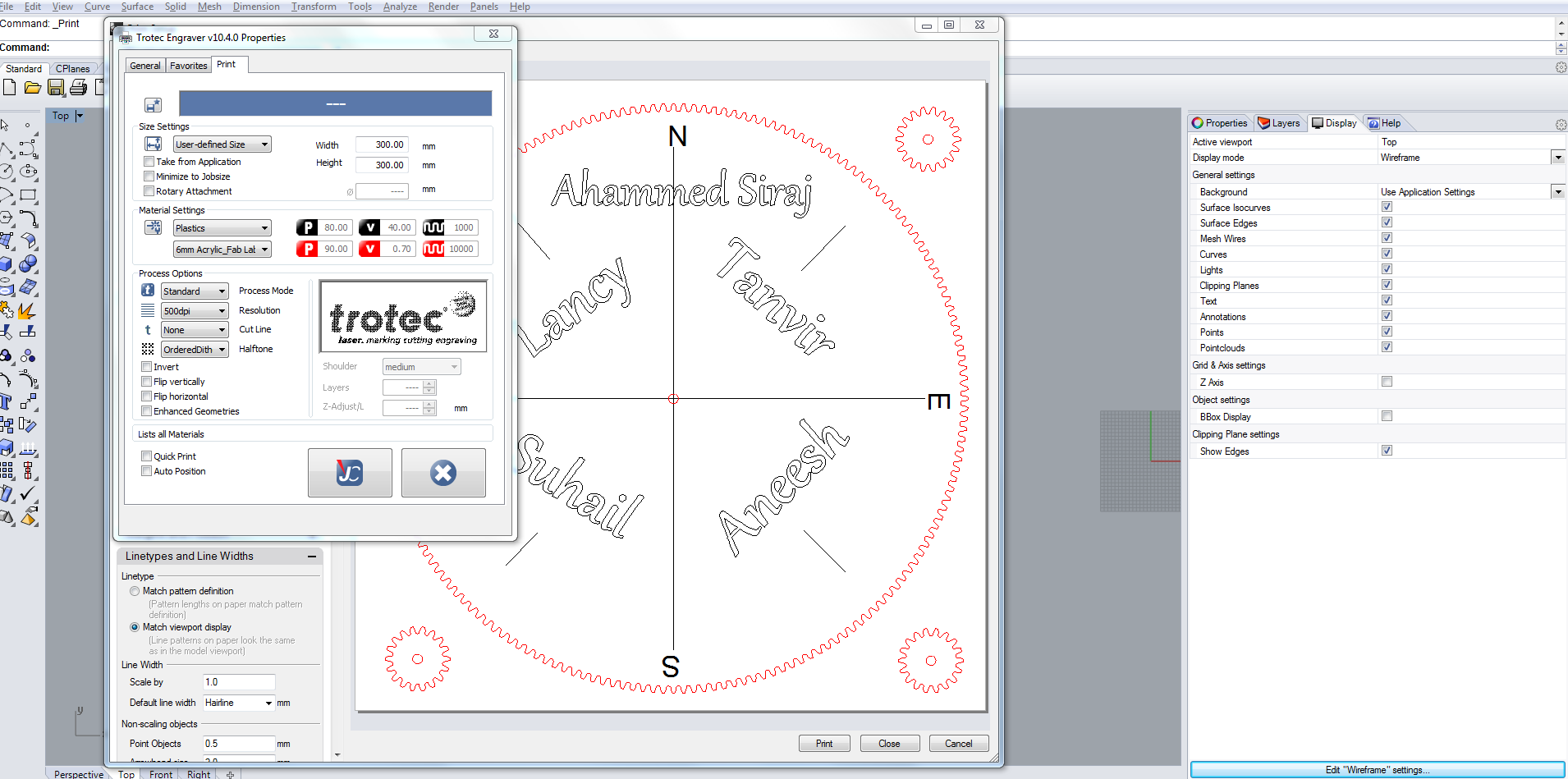
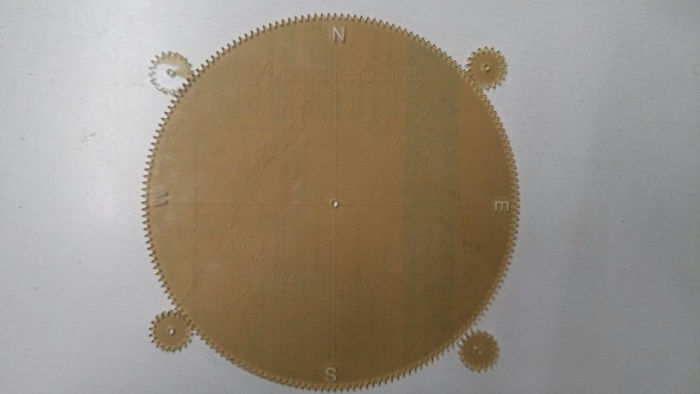
However, we decided to skip it and go on with regular 2 gear mesh system, for this we had calculated the required Parameters. Having set the required Outer Diameter of the driven gear as 280mm, Number of teeth to be 180, Gear ratio to be 0.1 and Diameteral Pitch as 1 and Pressure angle to be 20 degrees the following parameters were calculated:
| Number of teeth (N2=N1*Gear Ratio) | 18 |
| Outside diameter (OD2=(N2+2)/DP) | 30.77mm |
| Pitch Diameter (PD) :N/DP | 276.92mm |
| Root Diameter (RD=((N-2)/DP) | RD1: 273.85mm RD2: 24.62mm |
| Quarter Angle Circular Pitch (4ACP=(360/4)/N) | ACP1: 0.5 4ACP2: 5 |
| Pitch Point Diameter Circle (PPD=1/4*PD) | PPD1: 69.23mm PPD2: 6.92mm |
| Base Fillet (BF=.01*PD) | BF1: 2.7692mm BF2: 0.2769mm |
Note # The Driven gear is denoted as 1, and Driving gear as 2
Busy working on the group assignment. Some shots :-D
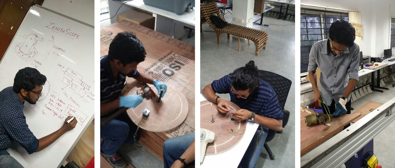
some fun in between :P
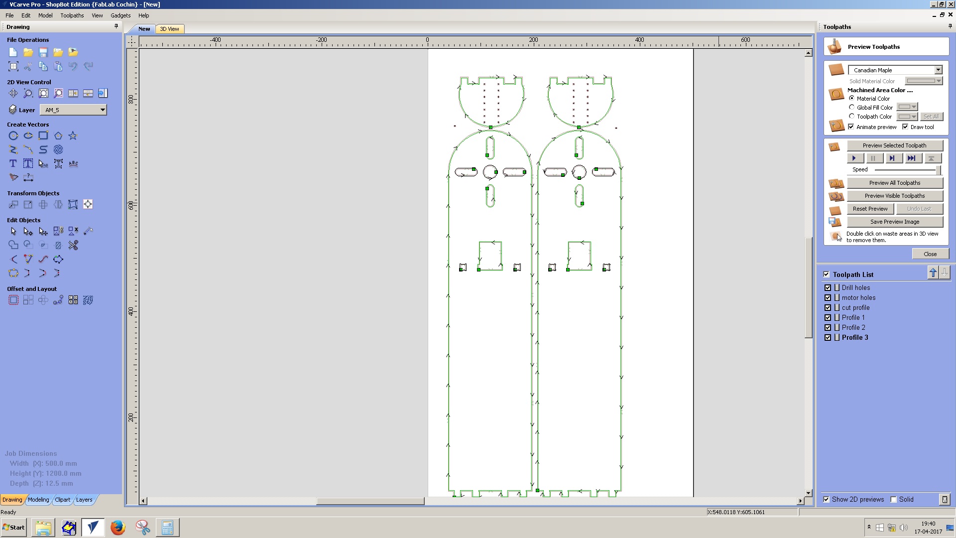
We then designed the vertical panel where the telescope is mounted. This contains 3 parts mainly. The vertical arm which is to be cut from plywood, a telescope mounting bracket which is to be 3D printed and a gear lock system for attaching side gear into the vertical arm. Vertical arm should also contain a slot for holding the stepper motor.
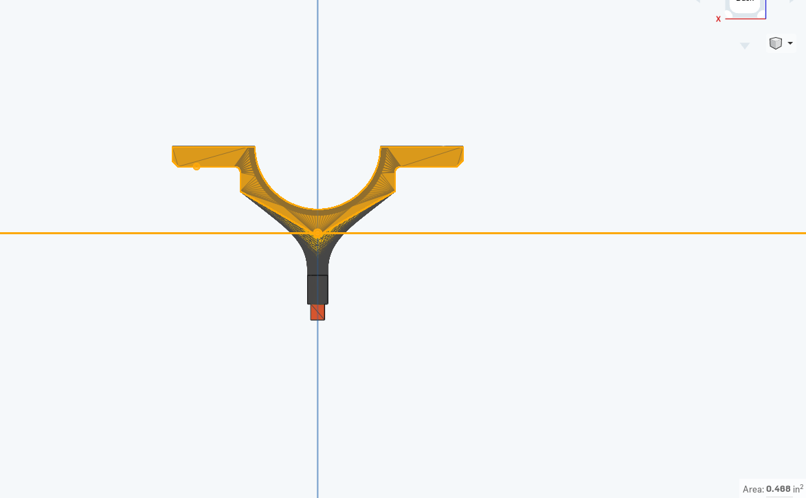
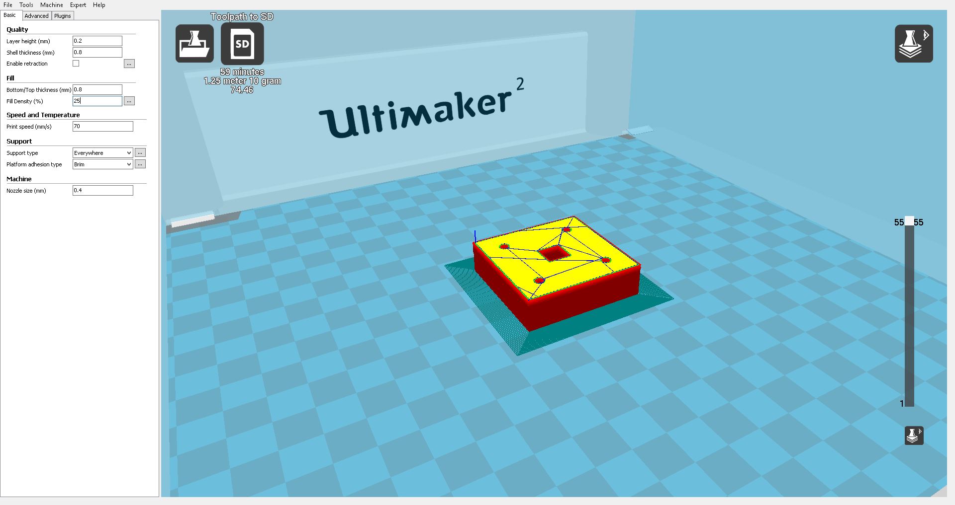
We calculated diameter of a telescope we had and designed telescope bracket in onshape. A screenshot is shown below.
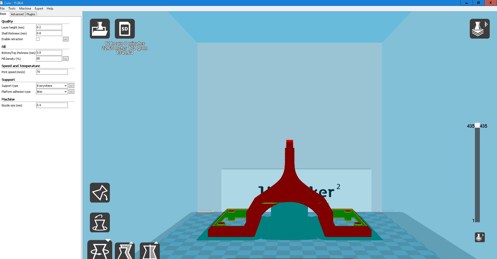
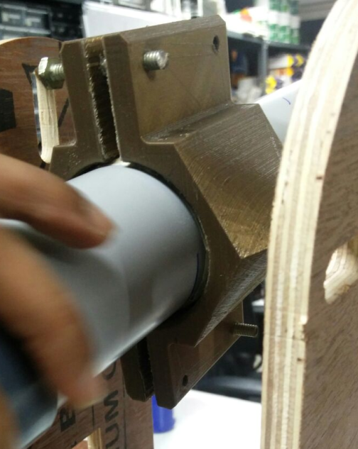
We printed two copies of the telescope bracket so that it can hold the telescope tightly. Both parts were connected together using nut & bolt. Image below shows telescope mounted using the bracket.
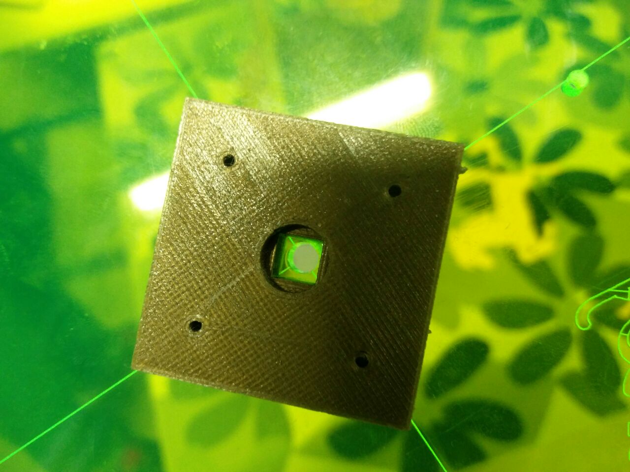
We need some mechanism to hold the side gear into the whole side arm. We decided to 3D print a lock which fits in telescope bracket and there are 4 holes in it for attaching the gear using nuts & bolts.
The gear was mounted on lock using fevicol which is then connected on either sides of arm.
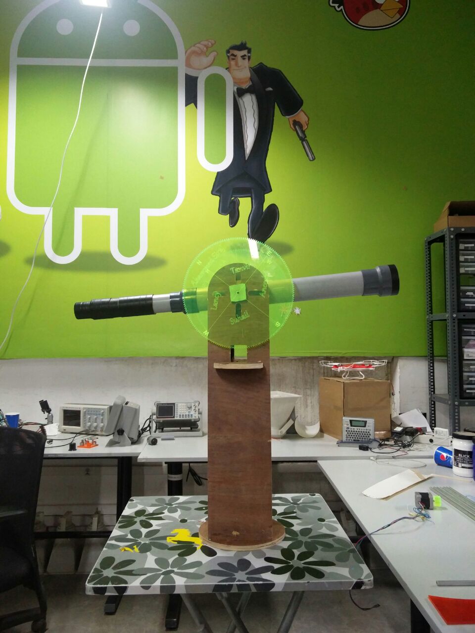
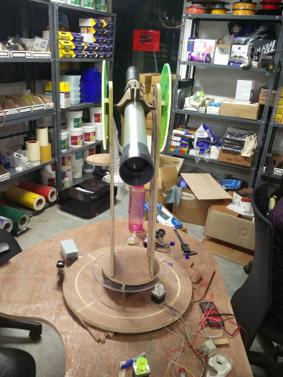
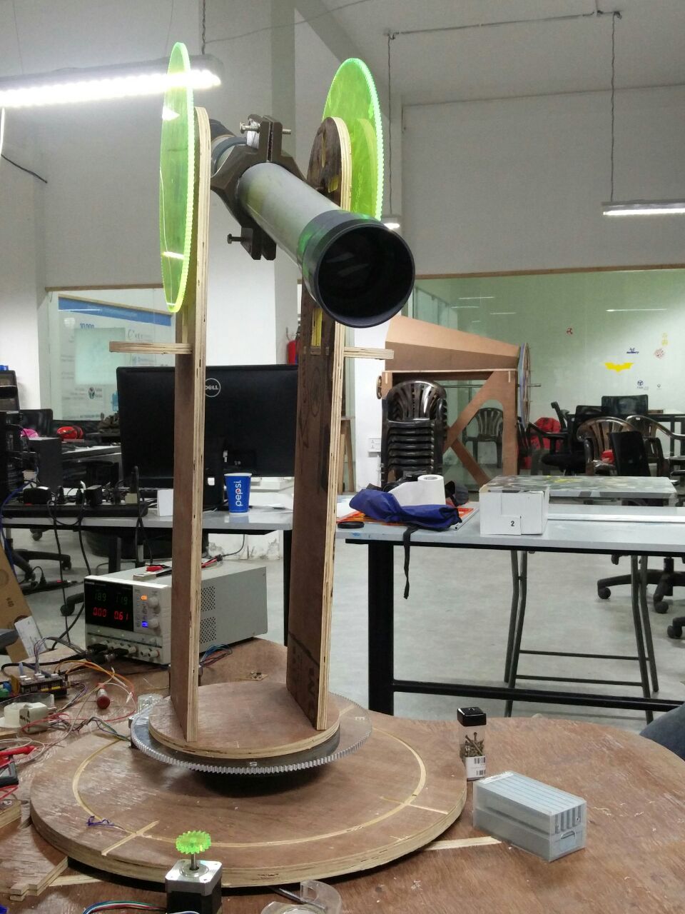
Now the mechanical section is finished. Hero shot of all parts assembled is shown below. Also, the video below shows the mechanical movement.