Machine Design
Team
Before moving onto automate the machine, it is essential to understand, the basic fundamentals on which the machine works.
For this we have researched, a bit on astronomy, and the calculations which are the backbone to the program.
Astronomy Basics and Principles.
As the basic objective of the machine is to point at celestial bodies automatically.It is essential that we know about their position relative to our own.
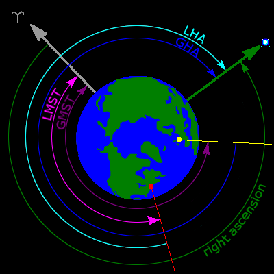
Right Ascension and Declination
The celestial bodies are all assigned a constant coordinate, to reference them.How we reference a location on Earth using latitudes and longitudes, the stars too have a sytem known as the right ascension and declination.
The celestial sphere is an imaginary sphere of arbitrarily large radius, concentric with Earth. All objects in the observer's sky can be thought of as projected upon the inside surface of the celestial sphere, as if it were the underside of a dome or a hemispherical screen. The celestial sphere is a practical tool for spherical astronomy, allowing observers to plot positions of objects in the sky when their distances are unknown or unimportant.
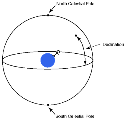
The above figure shows how the declination angle would be
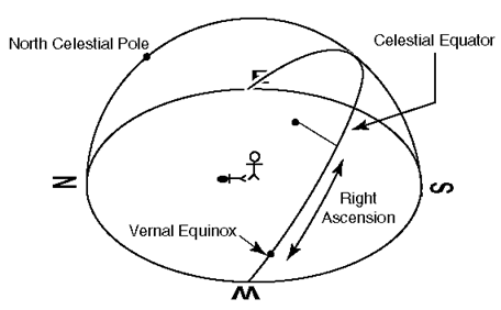
The above figure shows how the Right ascension would be.
The below video helped really well to understand what RA and DEC are.
Altitude and Azimuth
Now that we have understood where the celestial body is in the celstial sphere, we need to understand where it is relative to here we are.
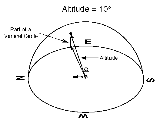
Altiude is the corresponding angle to Angle of Declination, in the local sphere.
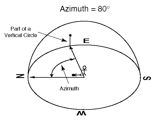
Similarly, the Azimuth corresponds to the Right ascension on the local sphere.
Calculations
The local cordinates has to be calculated from the known celestial cordinates. For that we use the following calculations.
Days since J2000 (d)
Many things (including the siderial time) are measured from fundamental epoch or date. For almost all the modern astronomical purposes, the reference date is J2000, which corresponds to 1200 hrs UT on Jan 1st 2000 AD, and we can use the table provided below to find how many days have gone by since J2000 for any date for the next 20 years or so.
The formulae can be given as
				d  = number of days from J2000(to current year) + number of days from start of current year to start of current month + number of days in current month + fraction of the day completed (current time/24)
				// {in 24 hour format}
Local Siderial Time
Sidereal time is the hour angle of the vernal equinox, the ascending node of the ecliptic on the celestial equator. The daily motion of this point provides a measure of the rotation of the Earth with respect to the stars, rather than the Sun.
LST = 100.46 + 0.985647 * d + long + 15xUT
- 'd' is the days from J2000, including the fraction of a day
- 'UT' is the universal time in decimal hours
- 'long' is our longitude in decimal degrees, East positive.
Add or subtract multiples of 360 to bring LST in range 0 to 360 degrees.
This formula gives our local siderial time in degrees. We can divide it by 15 to get our local siderial time in hours, but often we leave the figure in degrees. The approximation is within 0.3 seconds of time for dates within 100 years of J2000.
HOUR ANGLE(HA)
We can build in the Earth's rotation by replacing the RA by the Hour Angle. The HA of an object increases with siderial time, but the declination stays the same, as the DEC measures the angle from the Earth's equator. We calculate the HA in degrees, so that we can take sines and cosines later.
A can be calculated using the following formula
HA = LST - RAIf HA negative, we should add 360 to bring in range 0 to 360. RA must be in degrees.
			sin(ALT) = sin(DEC)*sin(LAT)+cos(DEC)*cos(LAT)*cos(HA)
			ALT = asin(ALT)

			cos(AZ)   =  sin(DEC) - sin(ALT)*sin(LAT)/ cos(ALT)*cos(LAT)
			AZ = acos(A)
If sin(HA) is negative, then AZ = A, otherwise AZ = 360 - A
Making the Machine understand
All the calculations we've done here so far are all in degrees. The problem with this is that even though it's easy to understand and convey this to others, the machine doesn't understand this. Here we used stepper motor. And for a stpper motor we have to calculate the steps. One step of a stepper is taken as 1.8 degrees.
1.8 degrees = 1 step
For more accuracy we can use microstepping. Here we used microstepping of 1/16
i.e, 1.8 / 16 = 0.1125
Therefore, for calculating the number of steps, we use the following formula.
Number of steps = no : of degrees/0.1125
This is the step equation
Electronics and Programming
Once we got the idea of how go-to telescope works and basic theories behind it, we moved to the programming section. We are going to use Funduino board we already have, with a RAMPS1.4 board which contains multiple Pololu stepper motor driver. We are using arduino IDE for programming.
Components
- RAMPS1.4
- Arduino Mega
- Pololu stepper motor
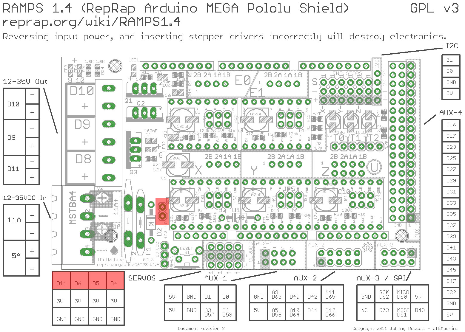
RAMPS

Ramps is short for reprap Arduino mega pololu shield, it is mainly designed for the purpose of using pololu stepper driven board (similar to 4988 driven board). Ramps can only work when connected to its mother board Mega 2560 and 4988/DRV8825.
The shield has following features:
- Standard interfaces (as that of extruder)
- Reserved GCI like I2C and RS232Reserved GCI like I2C and RS232
- MOSFET are applied to the heater/ fan and thermistor circuit.
- Adding another 5A to protect the component parts.
- An 11A fuse is added to the hotbed
- Support 5 stepper drive board
- The adoption of Pin Header as pololu makes it more convenient to repair or change.
- I2C and SPI are reserved for expanding
- All the MOSFET can be controlled by PWM
- Use the interface of servo motor to adjust the level of printing platform automatically.
- Adding a SD module for SD ramps module.
- LED can indicate the status of the heater (the open and close of MOS).
- 2 stepper motor for Z axis in parallel.
Image below shows the annotation diagram of RAMPS 1.4
Arduino Mega
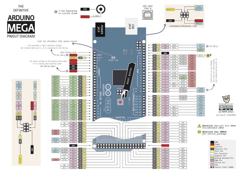
The Mega 2560 is a microcontroller board based on the ATmega2560. It has 54 digital input/output pins (of which 15 can be used as PWM outputs), 16 analog inputs, 4 UARTs (hardware serial ports), a 16 MHz crystal oscillator, a USB connection, a power jack, an ICSP header, and a reset button. It contains everything needed to support the microcontroller; simply connect it to a computer with a USB cable or power it with a AC-to-DC adapter or battery to get started.
We had mounted the RAMPS board over Arduino Mega. Schematic diagram showing connection setup between RAMPS and arduino mega is given below.
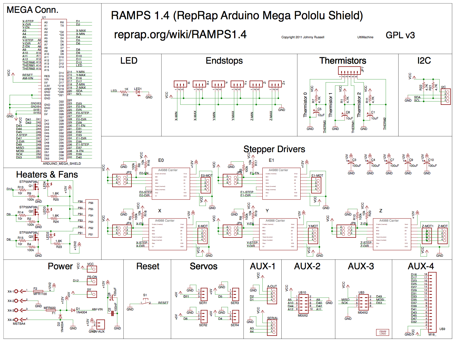
Image below shows the pinout diagram of arduino mega.
Pololu A4988
The A4988 is a microstepping driver for controlling bipolar stepper motors which has built-in translator for easy operation. This means that we can control the stepper motor with just 2 pins from our controller, or one for controlling the rotation direction and the other for controlling the steps.
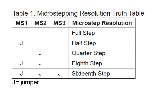
The Driver provides five different step resolutions: full-step, haft-step, quarter-step, eight-step and sixteenth-step. Also, it has a potentiometer for adjusting the current output, over-temperature thermal shutdown and crossover-current protection. Its logic voltage is from 3 to 5.5 V and the maximum current per phase is 2A if good addition cooling is provided or 1A continuous current per phase without heat sink or cooling.
Microstepping mentioned above can be set using 3 jumper pins. Jumper connection truth table for microstepping is shown below.
Program
		int leap_year = 0;
	  	//no.of days from beginning of year(normal)
	  	//jan-0, feb-31 etc
	  	int days[] = {0,31,59,90,120,151,181,212,243,273,304,334};
	  	//no.of days from beginning of year(leapyear)
	  	int days_leap[] = {0,31,60,91,121,152,182,213,244,274,305,335};

		//{degree,minute}
		int ip_dec[] = {-19,4.5};
		//{hour,minute}
		int ip_ra[] = {18,28.182};
		//{hour,minute} in 24HRS format
		int ip_t[] = {00,15};
		//{value in decimal}
		float ip_lat = 10.05542;
		//{value in decimal}
		float ip_long = 76.35792879999997;
		//date,month,year
		int ip_date[] = {18,4,2017};

		float pi = 3.1415;

		void setup() {
	  		int i,j;
	  		int base_correction = 0;

	  		//Initiate Serial communication.
	  		Serial.begin(9600);

	  		//pins for setting home position
	  		const int button_side = 32;
	  		const int button_base = 16;
	  		pinMode(button_side, INPUT);
	  		pinMode(button_base, INPUT);
			digitalWrite(button_side,HIGH);
			digitalWrite(button_base,HIGH);

			//STEPPER DATA
			// defines pins numbers
			const int enablePin_base = 24;
			const int stepPin_base = 26;
			const int dirPin_base = 28;
			const int enablePin_side = 30;
			const int stepPin_side = 36;
			const int dirPin_side = 34;

			pinMode(enablePin_base,OUTPUT);
			pinMode(stepPin_base,OUTPUT);
			pinMode(dirPin_base,OUTPUT);

			pinMode(enablePin_side,OUTPUT);
			pinMode(stepPin_side,OUTPUT);
			pinMode(dirPin_side,OUTPUT);

			//set enable pin
			digitalWrite(enablePin_base,LOW);
			digitalWrite(enablePin_side,LOW);

			//finding home position for base(azimuth)
			int button_base_val = digitalRead(button_base);
			while (button_base_val == HIGH) {
				digitalWrite(dirPin_base,HIGH);
				digitalWrite(stepPin_base,HIGH);
				delayMicroseconds(1000);
				digitalWrite(dirPin_base,HIGH);
				digitalWrite(stepPin_base,LOW);
				delayMicroseconds(1000);
				button_base_val = digitalRead(button_base);
			}

			//finding home position for side arm(altitude)
			int button_side_val = digitalRead(button_side);
			while (button_side_val == HIGH) {
				digitalWrite(dirPin_side,LOW);
				digitalWrite(stepPin_side,HIGH);
				delayMicroseconds(1000);
				digitalWrite(dirPin_side,LOW);
				digitalWrite(stepPin_side,LOW);
				delayMicroseconds(1000);
				button_side_val = digitalRead(button_side);
			}

			//After reaching home position
			float alt_val = get_altitude();
			float azimuth_val = get_azimuth();

			Serial.print(alt_val);
			Serial.print(';');
			Serial.print(azimuth_val);
			Serial.print(';');

			//telescope is not allowed to move backward. So if there is -ve value altitude,
			// azimuth should take extra 180 deg turn with alt value +ve.
			if (alt_val < 0) {
				base_correction = 180;
				alt_val = abs(alt_val);
			}
			if (azimuth_val < 0) {
				azimuth_val = 360 + azimuth_val - base_correction;
			}
			else{
				azimuth_val = azimuth_val + base_correction;
			}

			//azimuth should not be > 360 according to our mechanical setup
			if (azimuth_val > 360) {
				azimuth_val = azimuth_val -360;
			}

			//converting above values to steps
			//microstepping-1/16; 0.1125 deg = 1 step
			alt_val = alt_val/0.1125;
			azimuth_val = azimuth_val/0.1125;

			alt_val = alt_val*10;
			azimuth_val = azimuth_val*10;

			Serial.print('\n');
			Serial.print(alt_val);
			Serial.print(';');
			Serial.print(azimuth_val);
			Serial.print(';');

			//feeding steps to motor
			//base stepper
			for (i=0; i<=azimuth_val; i++) {
				//generate pulse for base motor
		  		digitalWrite(dirPin_base,LOW);
		  		digitalWrite(stepPin_base,HIGH);
		  		delayMicroseconds(700);
		  		//digitalWrite(dirPin_base,HIGH);
		  		digitalWrite(stepPin_base,LOW);
		  		delayMicroseconds(700);
			}
			for (j=0; j<=alt_val; j++) {
				//generate pulse for side motor
		  		digitalWrite(dirPin_side,HIGH);
		  		digitalWrite(stepPin_side,HIGH);
		  		delayMicroseconds(700);
		  		//digitalWrite(dirPin_side,HIGH);
		  		digitalWrite(stepPin_side,LOW);
		  		delayMicroseconds(700);
			}
		}


		void loop() {
			// we don't need this function
		}


		// to convert value in (degree,min) to degree
		float dec_to_degree(int val[]) {
			float result;
			result = val[0] + (val[1]/60.0);
			return result;
		}

		// to convert value in (hour,min) to degree
		float ra_to_degree(int val[]){
			float result;
			result = (val[0] + (val[1]/60.0))*15;
			return result;
		}

		// to convert value in (hour,min) to hour
		float time_to_hour(int val[]){
			float result;
			result = val[0] + (val[1]/60.0);
			return result;
		}

		//Local Sidereal Time
		//longitude,time,date as inputs
		float get_lst_value(float lngt, int t[], int dt[]) {
			float lst;
			//for calculate from epoch (reference date is J2000)
			//days from J2000 upto 2017 is 6208.5
			float total_days = 6208.5+(dt[2]-2017)*365 + time_to_hour(t)/24;
			//if leap year, add one more day
			if ((dt[2] % 4) == 0) {
		  		total_days += 1;
		  		leap_year = 1;
			}
			//add total days of current month and date
			//currently we processed only days in year
			if (leap_year == 1) {
				total_days = total_days + days_leap[dt[1]-1] + dt[0];
			}
			else {
				total_days = total_days + days[dt[1]-1] + dt[0];
			}
			//last element is time converted to GMT
			lst = float(100.46) + float((0.985647*total_days)) + float(lngt) + float(15*(time_to_hour(t)-5.5));
			return lst;
		}


		//to find Hour Angle (HA)
		//HA = LST - RA
		float get_ha() {
			float lst_ = get_lst_value(ip_long, ip_t, ip_date);
			float ra_ = ra_to_degree(ip_ra);
			float ha = lst_ - ra_;
			//float ha = (lst_ - ra_ + 360)- ((int)((lst_ - ra_ + 360)/360))*360;
			return ha;
		}

		//to calculate Altitude(ALT)
	 	float get_altitude() {
			float alt = asin(sin(dec_to_degree(ip_dec)*pi/180)*sin(ip_lat*pi/180)+cos(dec_to_degree(ip_dec)*pi/180)*cos(ip_lat*pi/180)*cos(get_ha()*pi/180));
			return alt*180/pi;
		}

		//to calculate Azimuth(AZ)
		float get_azimuth() {
			float a,az;
			a = acos((sin(dec_to_degree(ip_dec)*pi/180)-sin(get_altitude()*pi/180)*sin(ip_lat*pi/180))/(cos(get_altitude()*pi/180)*cos(ip_lat*pi/180)));
			a = a*180/pi;
			if (a>0) {
		  		az = 360-a;
			}
			else {
		   		az = a;
		  	}
			return az;
		}
Result
We ran the program to find the MOON on 4:10 pm, evening this was the result:
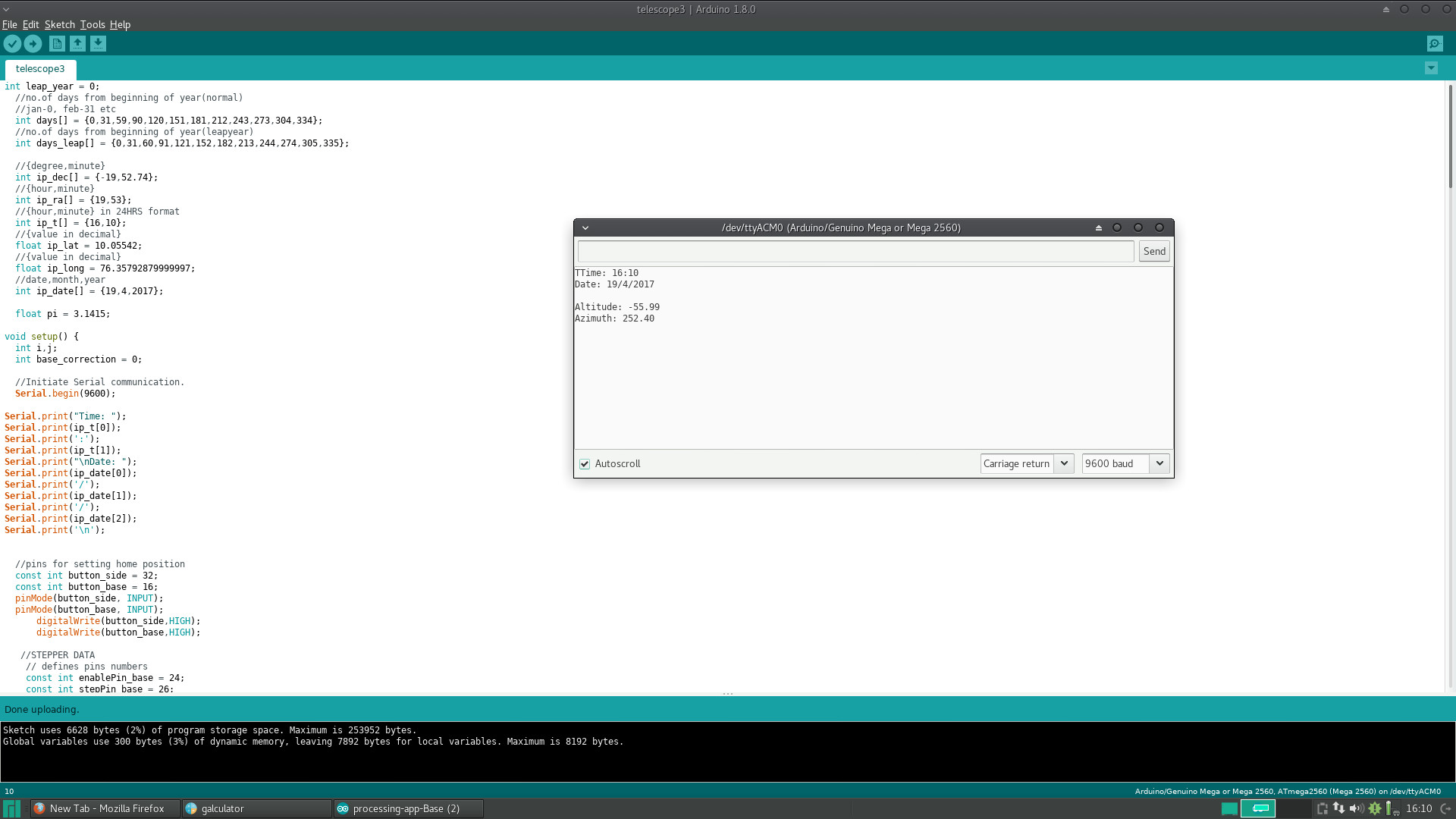
This the result we got from the Serial Monitor on Arduino
Altitude:55.9 degree
Azimuth : 252.40 degrees
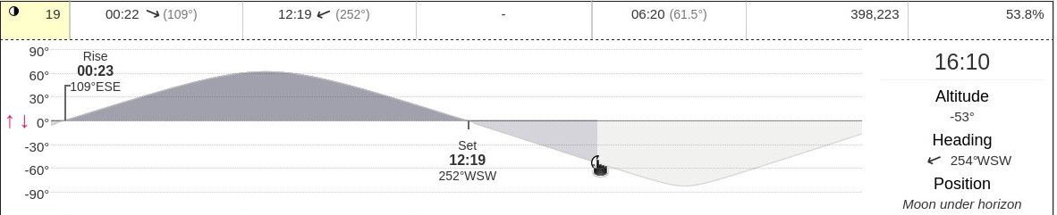
This closely mathes with the real time values, as seen from below:
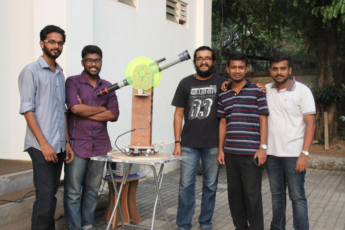
Hero Shots
Future Scopes
- Celestial body Auto Tracking Sysytem
- Wirelessly connected to mobile application for input
- Allow full rotaion by removing mechanical homing device.
- Predefined Celestial Body Coordinates in App
- Custom Coordinate input through app.
Output
Here is our project poster
Downloads
Arduino File : Download