[WEEK07] Computer-controlled Machining
What I made

I made a rack to organize tools and materials.
1. Tutorial
※I didn't use the part descrived in the following work flow in my product. Just for description.
1.1 CAM "Fusion 360"
Select [CAM] menu and move to CAM setting mode.

Register my mill in the "Local" folder.
[MANAGE]→[Tool Library]→[New Mill Tool]
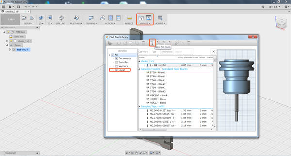
Input the information about my mill.

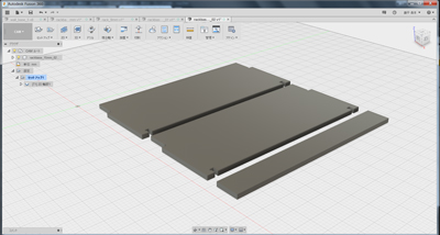
Set the informantion about a stock.
[SETUP]→[New Setup]
Set an axis orientation and a position of an origin. I selected [Select Z axis/plane & X axis].

Set the size of a stock.

Set a tool pass.
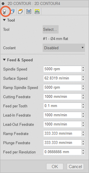
[2D]→[2D contour]

Select a tool and confirm settings below.
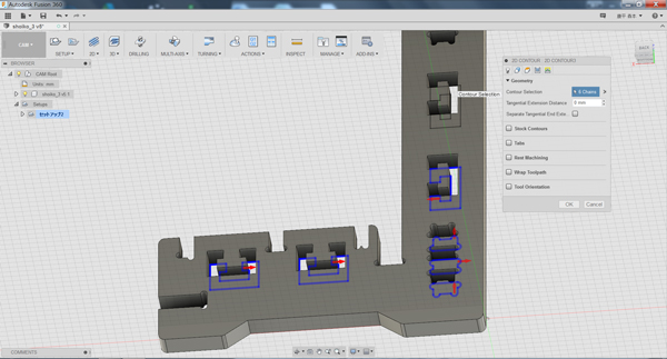
Select contours.
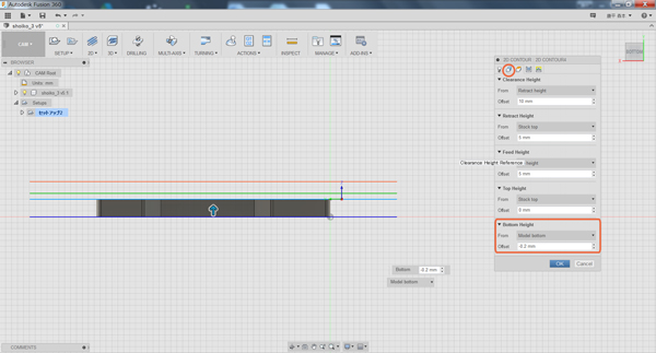
Set the Crearance Hight, Retract Hight, Feed Hight, Top and Bottom hight. I set the bottom hight to -0.2mm from model bottom to completely cut to the bottom.
Set the Maximun Roughing Cutdown I set it to half of the diameter of the mill.

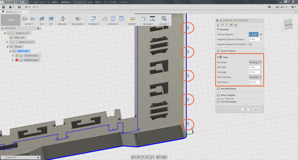
Set Tabs
If you want to make uncut part, you should select [Tabs] menu and input data. You can choose the size and the position of tabs.
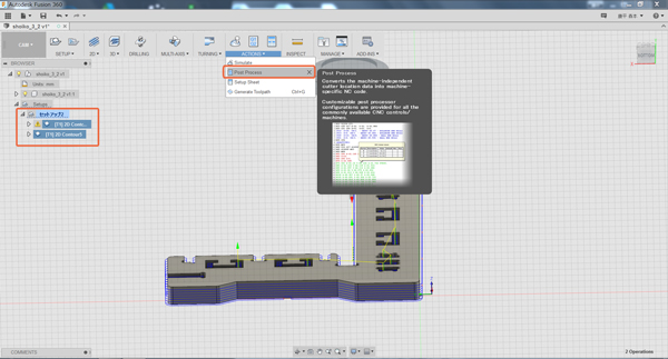
Export a Gcode data.
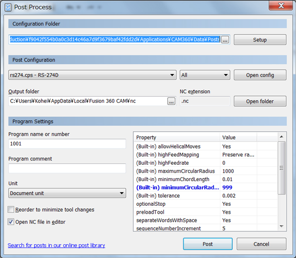
[ACTIONS]→[Post Process]
- Post Configuration: rs247.cps - RS274D
- [Prgram Settings]→[Property]→[minimumCircularRadius]: 999
Edit the Gcode file on editer as follow. If I skip this process,the tip of the endmill moves a surface of a material. After that, I copied the file to my USB and took it to the machine.

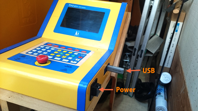
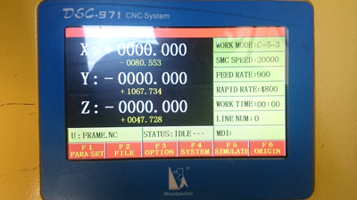
1.2 CNC Machine "Woodpecker"
This is a CNC machine in my lab. The work size of it is 1200mm x 1200mm.

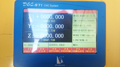
Press power button and insert USB memory. Press [F1] key to return to home.

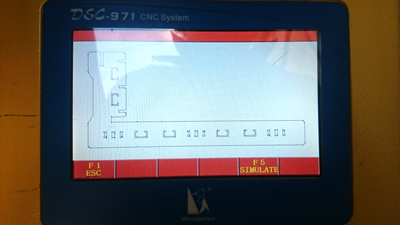
Press [F2] key x2 to check a file.
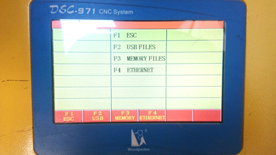
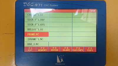
Select a file with [F3] key and press [F5] key x2. The tool path of the data to be processed is displayed on the monitor.
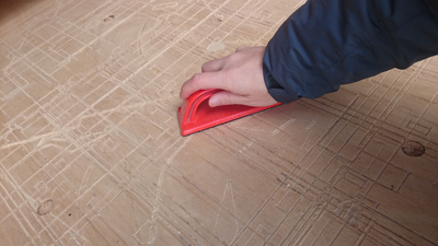
Brush the platform with a file to scrape unevenness. Fix a material with screw.

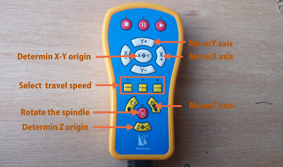
Set an origin briefly with a controller. Start machining without endmill and confirm that there is no screw on the tool pass.

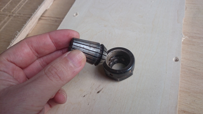
Attach a collet.
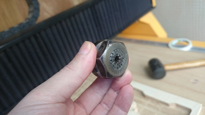
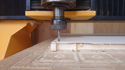
Attach an Endmill with two spanners. Set an origin acurately and press a start button.

2. Something Big
2.1 Tool Rack
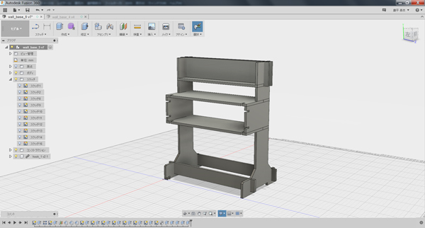
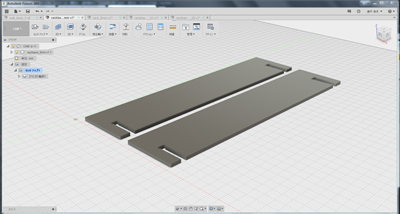
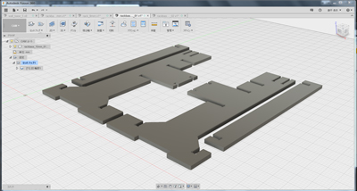
I made tool rack that used 3D printed parts for a joint. It conists of two bodies: a base and a board. The board can be fitted with parts made with 3D printer.And 3D printed joint parts were used for part of the base. At first I modelled the 3D data with Fusion 360 and created a Gcode file with Fusion 360 CAM.
I set the cutting conditions following the tutorial above.
- Endmill:Ø6mm Flat
- Maximum Roughing stepdown:3mm
- Climb milling


I assembled the base.I put a square logs on the both sides of the board with screws.
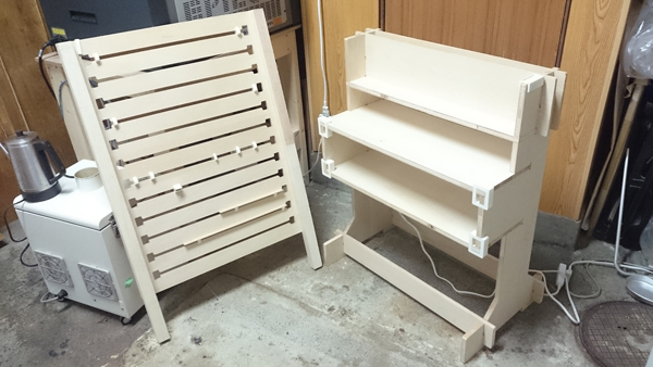
It was completed by putting the square logs on the base.

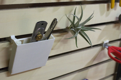
3D printed Joint pars

I designed the width of 3D printed parts and slot. But the measured size of these were a bit different. So It was very tight. When I attatched to the base, I used a rubber hummer. But I think It became strong joint.Considering to disassemble, it may be difficutl to adjust the size of slot and 3D printer parts.

Attachment parts


Download

rack_9mm(.iges): Download the file
rack_9mm(.nc): Download the file
rack_9mm(.dxf): Download the file
rackbase_9mm(.iges): Download the file
rackbase_9mm(.nc): Download the file
rackbase_9mm(.dxf): Download the file
rackbase_15mm_01(.iges): Download the file
rackbase_15mm_01(.nc): Download the file
rackbase_15mm_01(.dxf): Download the file