[WEEK06] Electronics Design
What I made
I designed electric circuit based on a sample and made circuit board using it.
1. Circuit board design
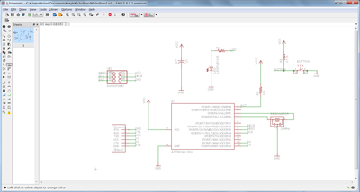
I drew the circuit for the echo hello-world board being added a button and LED. I choiced the EAGLE as a schematic design software because there were many tutorials and it was free.
1.1 Designing schematic
Download Library
Download library for hello echo board from here. Move it to the following folder.C:\EAGLE 8.0.2\lbr
Select [Library] menu from the side bar and right click on the [fab.lbr] and select [use].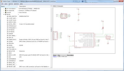
Make file
Make a new project file and name it "EchoBoard".[File]→[New]→[Project]
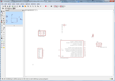
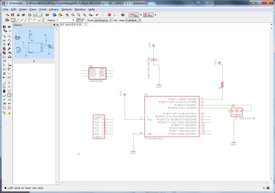
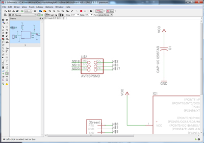
Right-click on an "Echoboard" in the side bar and select [New] and [Schematic].Design schematic
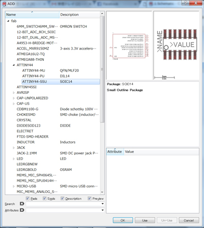
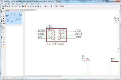
Use some commands from side tool bar to make schematic.Add: Select a necessary component from the window and push the [OK] button.Rotate right click Move:Click a + mark on the component and drag a mouse to move each component. Net:Connect each component or terminal. Label:Label each component or terminal. Name:Name the label. Value:Set a value to the label.
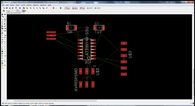
1.2 Designing board layout
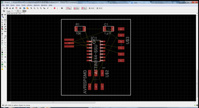
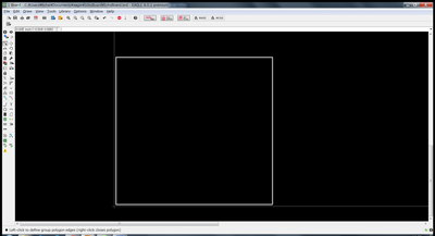
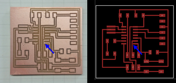
There is a button to switch between a schematic and a board layout on the tool bar above. Generate and switch to a board file by pushing it.Displey and set a grid [View]→[Grid]→[Display:on] At first, I set a grid pitch to 0.05 inch. But finally,I set it to 0.01 inch because I wanted to adjust the distance of some lines finely. Move:Click a + mark on the component and drag a mouse to move each component. In the case of moving multiple parts at the same time: [Move]→[Group]→[Move]→select components→Right Click→Drag Route:Connect each component or terminal. When I make a mistake, I use a Ripup command. Line:Draw an outline.

1.3 Export
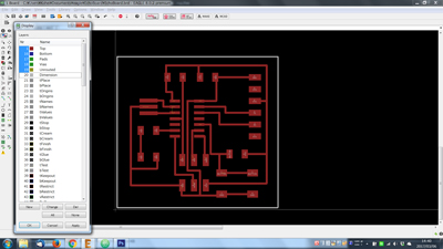
Push a layer setting button and Select a necessary layer.
Trace: [Top][Bottom][Pads][Vias][Unrouted] Outline: [Dimension]
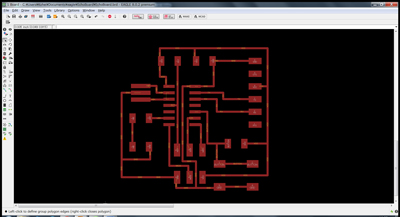
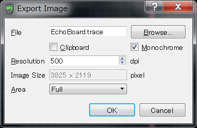
Export as "image". Settings was as follow.
Download
EchoBoardLED (.sch): Download the file
EchoBoardLED (.brd): Download the file
EchoBoardLED_trace_final(png): Download the file
EchoBoardLED_outline_final(png): Download the file
eagle_EchoBoardLED.zip(all eagle files)/: Download the file
2. Making a circuit board
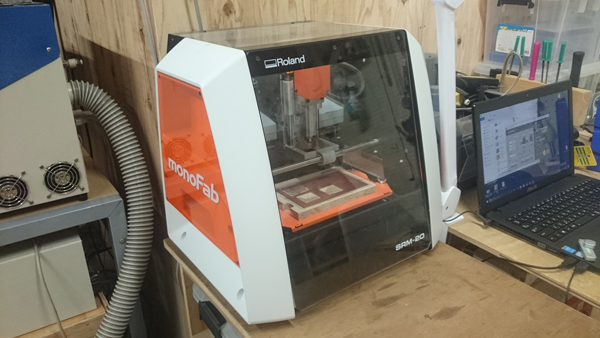
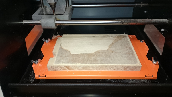
2.1 Milling machine
I used SRM-20 for milling a circuit board. After shaping the surface, I set a material (FR1) on it with double sided tape.
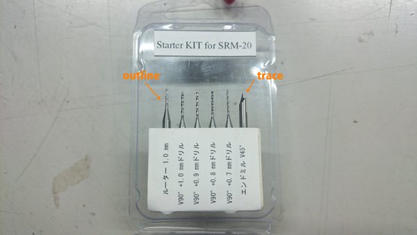
Endmills
I used the endmills as follow.- Trace: Endmill 45°
- Outline: 1.0mm
2.2 Miling a circuit board
I set the tool pass with Fab Modules. I tried several times because it did not work at once.
First trial
I set fab modules as follow.tool diameter (mm): 0.4mm number of offsets:4 offset overlap (%):50
Failed: The area where the line distance was narrow was not cut.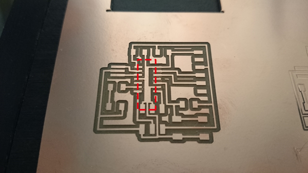
Second trial
I redesigned the board layout on EAGLE.Move the component (6 pin header) . Change the width of line that connected to each other in the first trial. (0.016 inch →0.008 inch)
I change the parameter of Fab Modules.tool diameter (mm): 0.2mm number of offsets:3 offset overlap (%):60
Failed: Close line and parts were connected.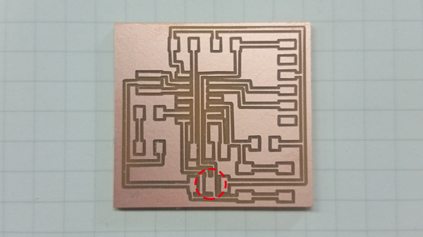
Third trial
The line passing between the pads was close to one of them. So I changed the grid width from 0.01 inch to 0.005 inch and let the line pass through the middle between the pads. I thought it was succeeded. (Actually it was a failure.)
Download
EchoBoardLED_trace_final(rml): Download the file
EchoBoardLED_outline_final(rml): Download the file
3. Asssembly
3.1 Components
| Part name | Quantity |
| ATTiny44A-SSUR | 1 |
| Capacitor 1uF | 1 |
| Resistor 10K ohm | 2 |
| 20MHz Resonator | 1 |
| 6-pin programming header | 1 |
| FTDI header | 1 |
| Button | 1 |
| LED | 1 |
| Resistor 499 ohm | 1 |
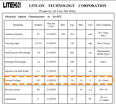
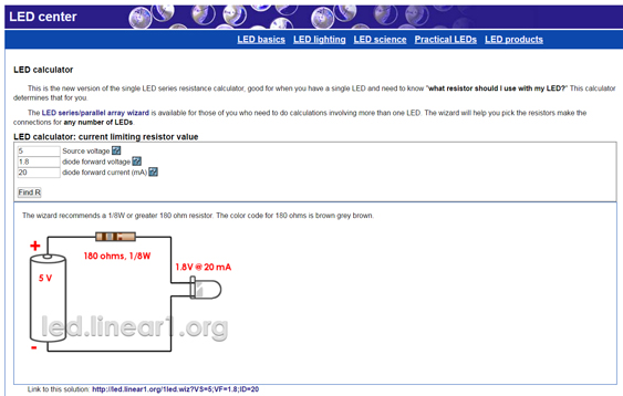
I checked the specification of LED (160-1167-1-ND) to calculate a resistor value for LED. I used the calculator in this page and decided to select 499ohm resistor.
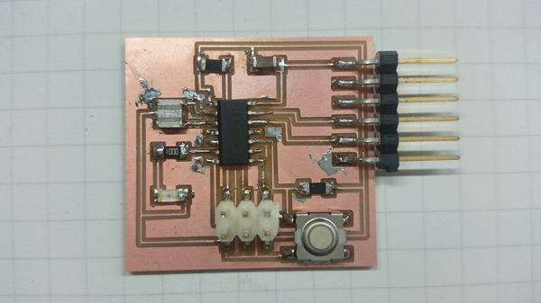
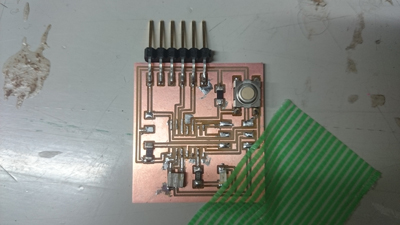
I soldered all components.
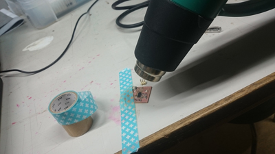
After assembly, I checked wheather it was soledred correctly with digital multimeter. When checking the continuity of adjacent terminals of 6 pin header, the alarm sounded. At this time, I noticed that there was a mistake left.
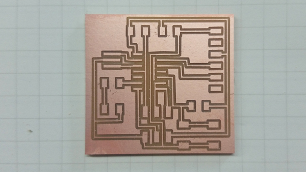
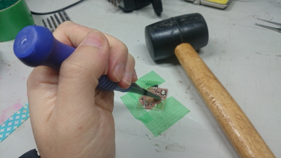
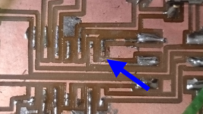
 I removed the parts with hot air gun and cut the unnecessary line with chizel.(If I had a hand router at that time, I used it.)
3.2 Test
I connected to AVRISP mk2 and Mac and confirmed that green light turned on, I will do further tests.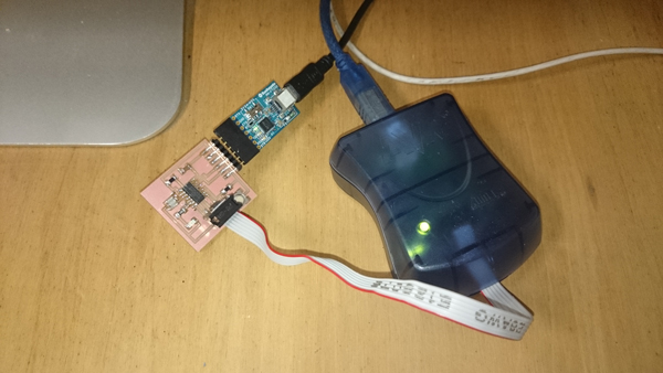
!!Additional comment after feedback!!
In this time, I definitely wanted to make sure that the soldering was done well and there was no short-circuit. So I used AVR ISP mk2 which is a more reliable device than Fab ISP that I made. Fab ISP was done well as shown in week08.
4. What I learnt for circuit design
Design rule for circuit design software (EAGLE).- Line width: usually set 0.016 inch. When the spacing between the parts is narrow,set it to 0.008 inch.
- The cuttable distance between parts or lines is about 0.018 inch or more. It can't mill when it is 0.005 inch or less.
- When making a small circuit, it is better to narrow the grid width (about 0.01 inch).
- Reduce a tool diameter
- Reduce a number of offset