FINAL PROJECT - PROTOTYPING
CONTENTS
Click on any of the links below to see further details about the final project.
- Project management: Checklist of the project's gradual development.
- Concept: General draft of the first conceived idea.
- 2D/3D design: Summary and steps of the design process.
- Electronic production and design: Details, design and production of the main board for the project.
- 3D printing, laser cutting and prototyping: Further details about the production of the robot's parts.
- Embedded, application and interface programming: Networking, motor control and web interface.
- Final project summary: Video demonstration, bill of materials, files of the final robot and general summary.
SUMMARY
3D PRINTING
TRACKS PROTOTYPE v.1.0 3D printing
Before printing, I quickly modified the design of the gear to reduce the body of the driving gear.
Fusion 360 can test joints of pieces, it is very useful. However, I wanted to try out how sturdy and precise it will look 3D printed.
The Ultimaker 2 extended + with a 0.8mm nozzle is used to test-print the tread and gear.
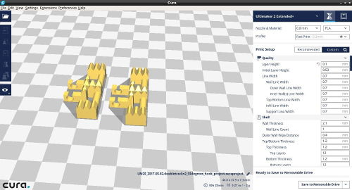
I wanted a fast print with easily removable supports. The 3D printing was done using CURA

The settings are the following:
Ultimaker 2 Extended +
0.8mm nozzle PLA
profile: Fast print

QUALITY
layer height: 0.6mm

SHELL
wall thickness: 2.1mm
top/bottom thickness: 1.2mm

INFIL
infil density: 20 %

MATERIAL
enable retraction: TRUE

SPEED
print speed: 30 mm/s
travel speed: 120 mm/s

COOLING
enable print cooling: true

SUPPORT
enable support: true
support placement: touching buildplate
support overhang angle: 50
support pattern: triangles
support density: 10%
support x/y distance: 1.2mm

BUILD PLATE ADHESION
build plate adhesion type: brim
brim width: 8mm

PRINT SEQUENCE:
all at once
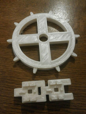
The quality of the 3D print was surprisingly reasonable, considering the speed of the printout is around 1 hour.
The tank-tread printed with slight disperfections. Print layers are very visible, precise areas like the holes on the sides, printed too. The support was easily removed.
The sprocket prototype also printed without problems, the support was a bit harder to remove; perhaps changing the support z distance would have helped. The final piece is good enough to provide traction; however, it can definitely be improved.
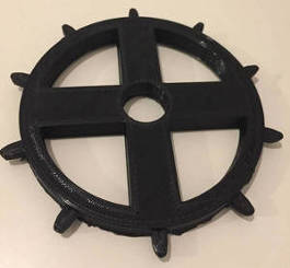
The first prototype needs improvement; the tank tread needs more aesthethic enhancements and the dimensions of the hole need to have more clearance for the sprocket teeth.
The print quality should improve with high-quality settings.
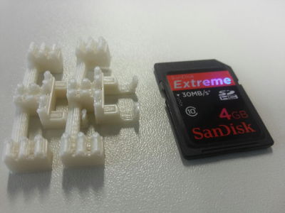
More test were ran to find the limits of the 3D printer.
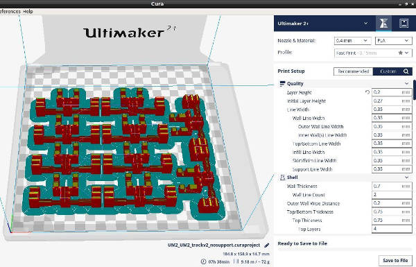
I tried to fast 3D print two interconnected treads, the result was unsatisfactory; perhaps due to the quality and speed of the print. CURA settings were the following:
//NOZZLE
0.8

//MATERIAL
PLA

//PROFILE
FAST PRINT

//QUALITY
layer height: 0.5

//SHELL
wall thickness: 2.1
top/bottom thickness: 1.2

//INFILL
infil density: 20%

//MATERIAL
enable retraction: true

//SPEED
print speed: 30
travel speed: 120

//COOLING
enable print cooling: true

//SUPPORT
enable support: true
support placement: touching buildplate
support overhang angle: 50
support pattern: triangles
support density: 10%
support z distance: 0.2mm
support x/y distance: 1.2mm

//BUILD PLATE ADHESION
build plate adhesion type: brim
brim width: 5mm
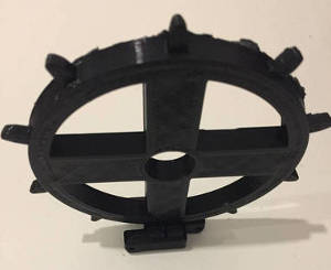
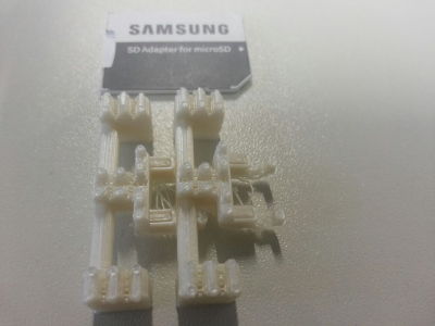
Similarly, a slightly modified version of the driving-gear was printed with the following settings:
//NOZZLE
0.8

//MATERIAL
PLA

//PROFILE
FAST PRINT

//QUALITY
layer height: 0.6

//SHELL
wall thickness: 2.1
top/bottom thickness: 1.2

//INFILL
infil density: 10%

//MATERIAL
enable retraction: true

//SPEED
print speed: 50
travel speed: 120

//COOLING
enable print cooling: true

//SUPPORT
enable support: true
support placement: touching buildplate
support overhang angle: 50
support pattern: triangles
support density: 5%
support z distance: 0.8mm
support x/y distance: 1.2mm

//BUILD PLATE ADHESION
build plate adhesion type: brim
brim width: 5mm
Print quality of the gear was lower than in the first test. Support this time was also more difficult to remove.
TRACKS PROTOTYPE v.2.0 3D PRINTING
Second prototype of the tracks is also printed using cura and an ultimaker 2+ extended 3D printer.
Scale is reduced to 50% and the following settings are applied:
//NOZZLE
0.1

//MATERIAL
PLA

//PROFILE
FAST PRINT

//QUALITY
layer height: 0.6

//SHELL
wall thickness: 2.1
top/bottom thickness: 1.2

//INFILL
infil density: 10%

//MATERIAL
enable retraction: true

//SPEED
print speed: 50
travel speed: 120

//COOLING
enable print cooling: true

//SUPPORT
enable support: true
support placement: touching buildplate
support overhang angle: 50
support pattern: triangles
support density: 5%
support z distance: 0.8mm
support x/y distance: 1.2mm

//BUILD PLATE ADHESION
none
In the same manner, several small-scale prototypes are printed with different settings for the 'track-hook', before printing the full-scale model.
First print used a print-speed of 50 and a hook size of 305 degrees. The fit was reasonable and friction low.
Second print used a higher print speed of 80 and a hook size of 300 degrees, quality was inferior and hook still tight but slightly loose.
The next four small-scale prototypes are printed using a speed of 50.
First, hook had a 305, second a 300, third 295, fourth 290, fifth 315, sixth hook had a new design with a 320 degree hook.
Last design is the preferred one.
Next is the printout of 22 tracks for the two sides of the robot.
Design is exported as .STL from Fusion360 and imported into meshmixer.
In meshmixer I manually added support structure using cilinders.
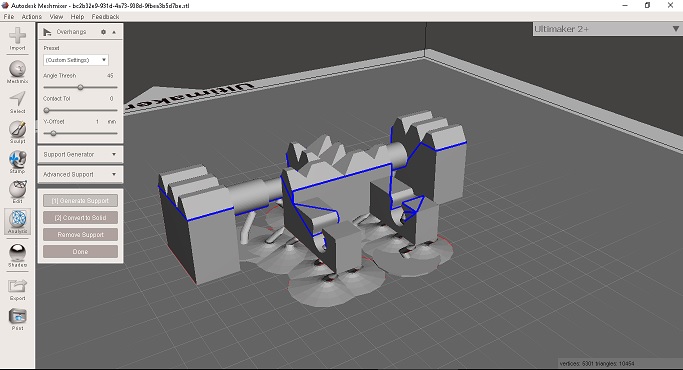
Similar supports were added for the sprockets.
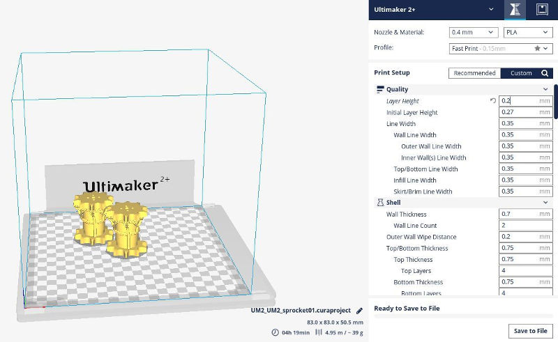
Print settings in cura were the following:
  CURA PRINT SETTINGS
- 0.2 layer height.
- 20% infill density.
- Rectilinear infill pattern.
- PLA.
- Speed 50 mm/sec
- No support. (Already added manually using meshmixer).
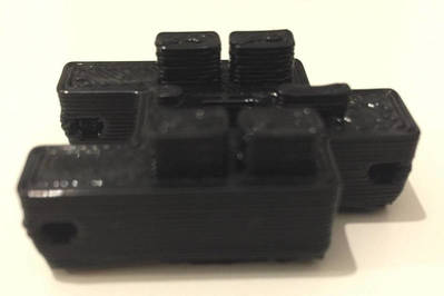
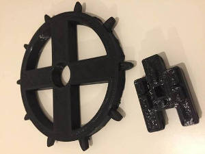
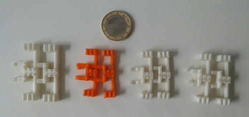
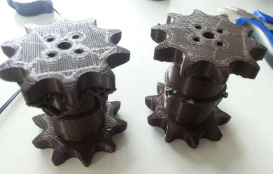
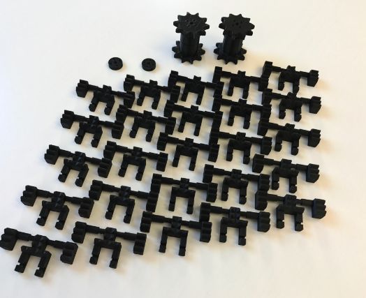
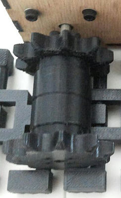
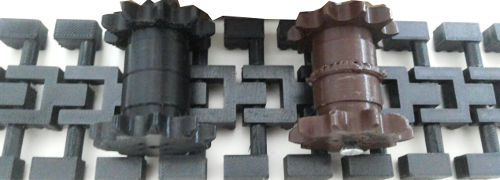
Two sprockets are printed:
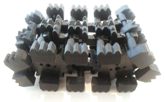
Final printout before removing the support structure:
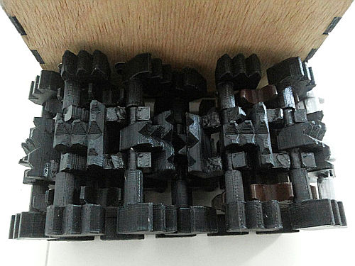
Similarly, 22 tank threads are printed using the built-in support generator in cura:
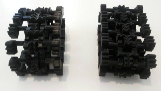
After printout threads are assembled to test.
The two assembled tracks:
LASER CUTTING
Epilog Laser Fusion M2 is used to laser cut.
ROBOT BODY V1.0 6mm thickness for Nema17
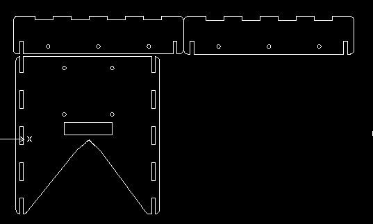
Robot body from the design page was laser cut.
DXF is first exported from Fusion 360 and imported into Draftsight.
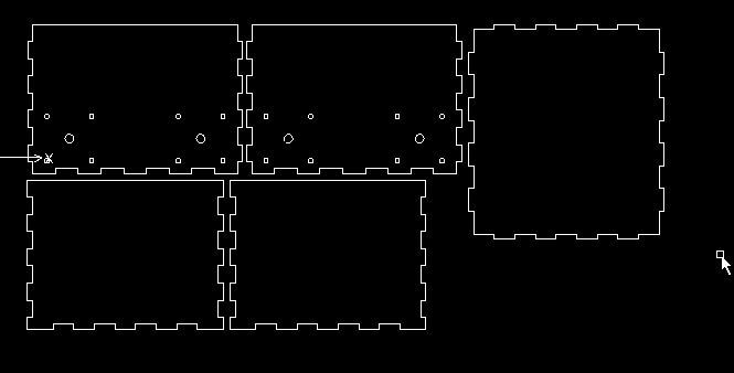
Following settings were applied:
6mm MDF stock material
speed: 7%
power: 100%
frequency: 30
The cut looked as follows:
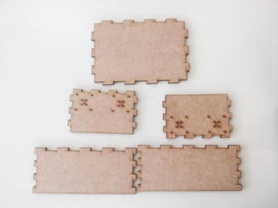
ROBOT BODY V1.0 3mm thickness for Nema14
Seeing that perhaps a Nema17 is too big for the tracks; I redesigned the box so it can fit a Nema14 motor with a slightly shorter width.
Following settings were applied:
3mm stock material
speed: 10%
power: 100%
frequency: 20
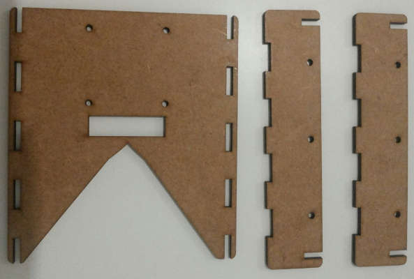
Cut came satisfactory, assembled body:
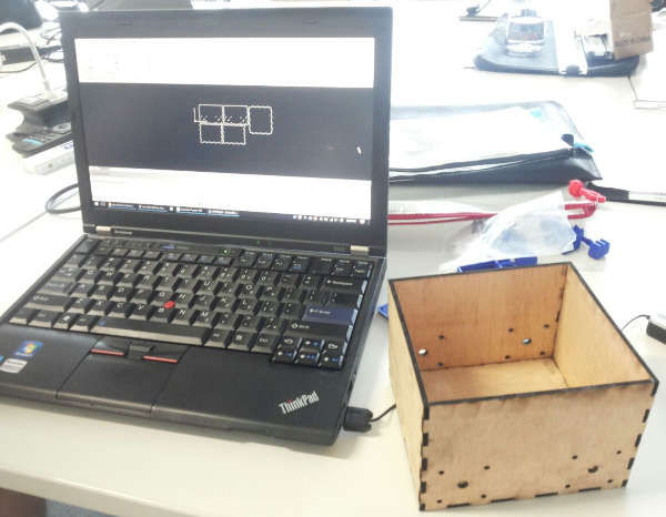
Top of the body is designed and cut to fit a pan and tilt camera.
ASSEMBLY OF WATCHOBOT V0.1
In order to assemble the laser cut prototype of watchobot v0.1, the following is needed:
=======================
BODY
=======================
Main frame - Robot body v1.0 3mm thickness Nema14
2 nema 14 motors
16 m3 screws
2 (1x5x8)cm blocks for mounting motorless sprockets
=======================
TRACKS
=======================
4 motor mounts
16 m3 screws
4 sprockets
2 4.5mm diametre 10cm long screw and nut
22 tank treads

=======================
ELECTRONICS
=======================
1 jc-watchobot v3.0 board
1 9V battery
1 voltage regulator
1 S3 11.1V lipo battery

=======================
CAMERA
=======================
1 pixy camera
1 pan and tilt
4mm laser cut top camera mount
4 m3 screws
First the body is laser cut and joined together.

3D printed tracks are prepared for assembly too.
Two of the motor-less driving sprockets are connected using two 4.5mm diametre 10cm long screws and two blocks of 1x5x8 cm of dimension..
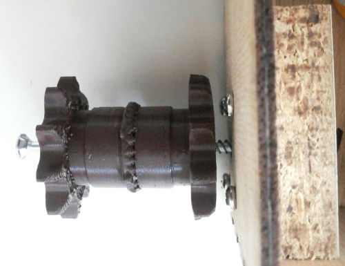
2 nema14 Motors are mounted to the body with 4 m3 screws and the shaft of each of the two motors is coupled with the black driving sprockets and mounting hubs (which need extra 4m3 screws).
Hook the treads, 11 on each side, and lay at bottom of the two driving sprockets.
Close the treads carefully.
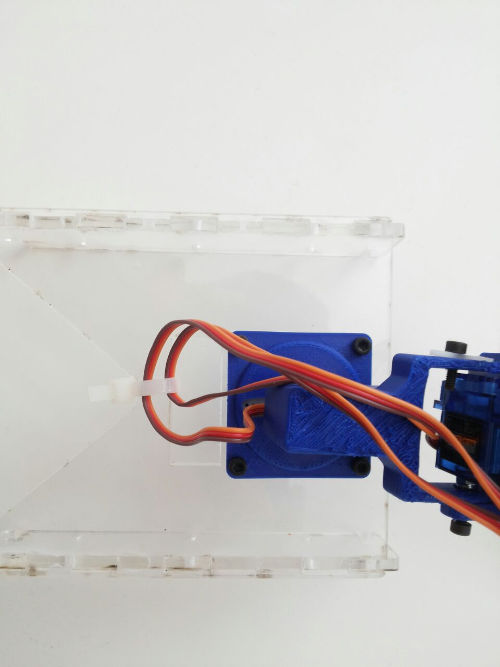
Prepare top mount for the camera.
I lasercut a mount in acrylic for better aesthethics.
Mount the pan and tilt mechanism with 4 m3 screws.
Carefully lock the cables in place in the hole.
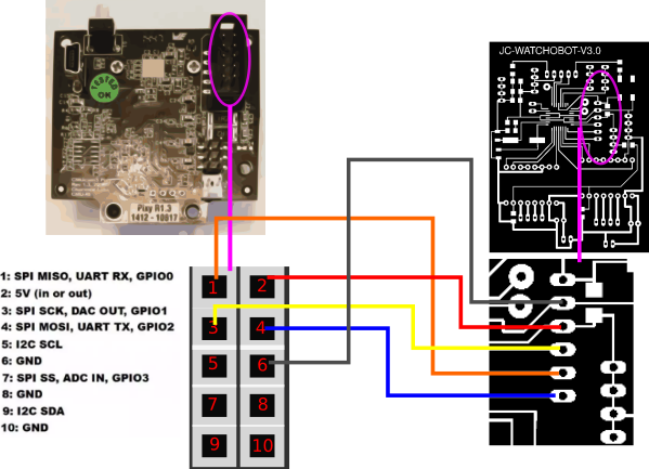
Next connect the jc-watchobot v3.0 as follows:
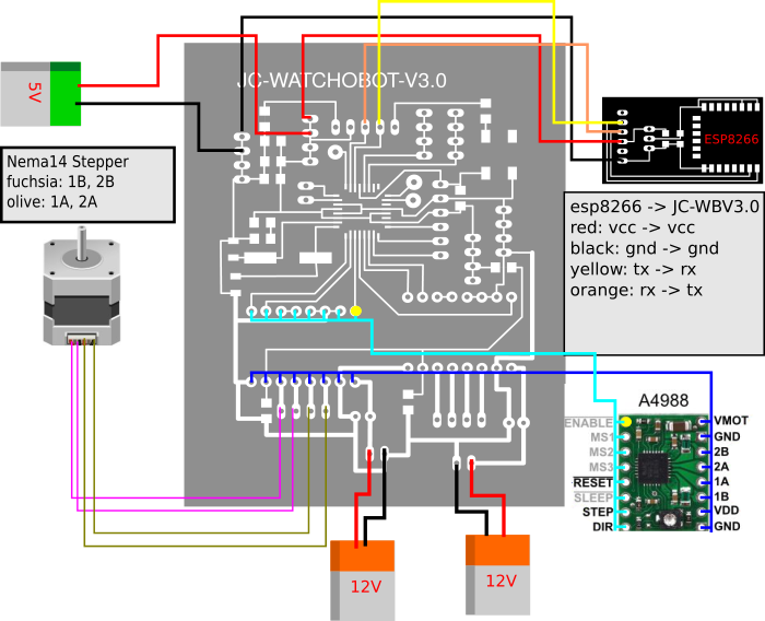
Keep cables tidy and tie up groups of cables.
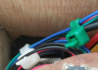
Similarly wire the pixy camera as follows.
FILES
All 3d files can be found in the design page here.