Week 8:
Embedded Programming
Programming the LED and button board
The goal is to programm the LED and button board that had been created during week 6 and to use as the programmer the FAB ISP that had been created during week 4.
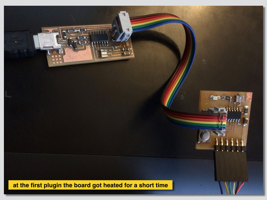
Starting from the micro-controller that got heat at the start was like trying to bring it back to live with tiny hope that it hadn’t been cooked.
My first few attempts came out unsuccessfully. There is much more about my failed attempts and also some success to make the LED blink on my week 6 page and to programm the programmer on week 4 page.
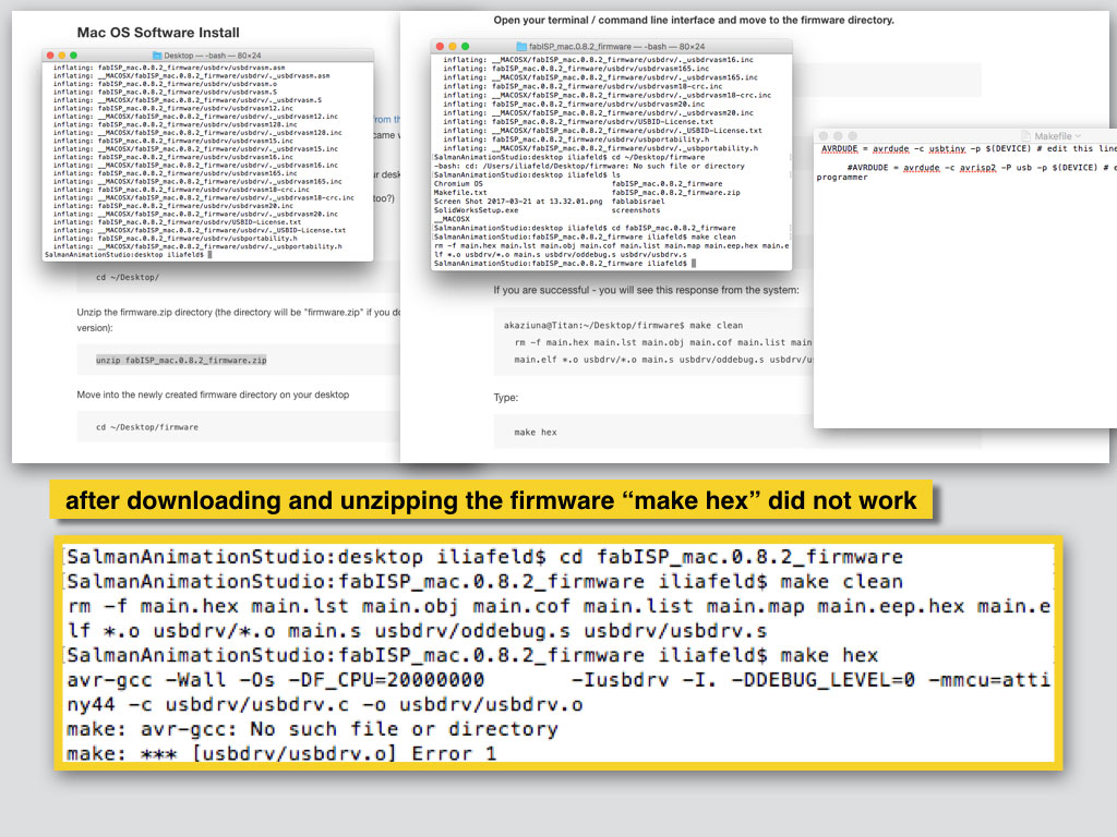
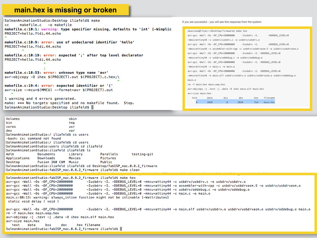
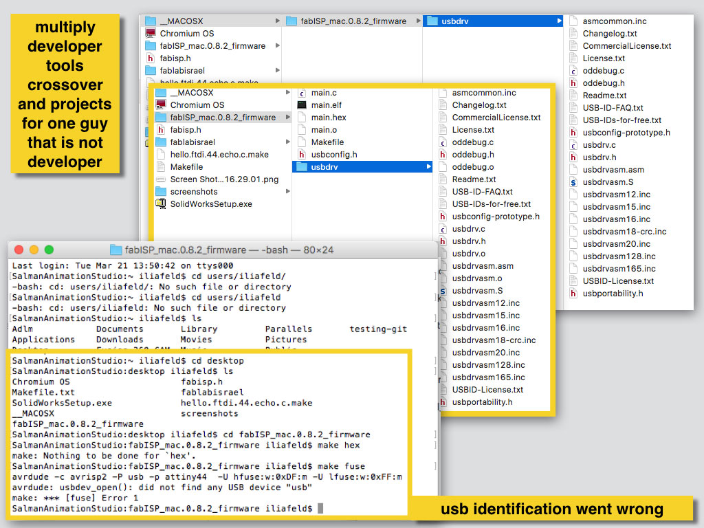
The three following images shows some of the difficulties I had while trying to load the firmware to FAB ISP programmer.
After finishing the process with ATTiny I tasted from alternative platforms to expend my tool-box.
I wondered about commercial board. How comfortable are the working workflow and environment that are provided with the product?
I needed to figure out how far can I get in inputs and outputs programming from my almost 0 knowledge just in few days. The progress was unexpectedly huge in my self measurements scale, even if it isn't about direct objective of this week assignment.
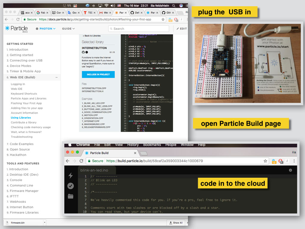
First I found this small kit with Photon board from Particle. It included the board itself, one LED, one LDR photoresistor, two 10k resistors, small breadboard and short mini USB cable.
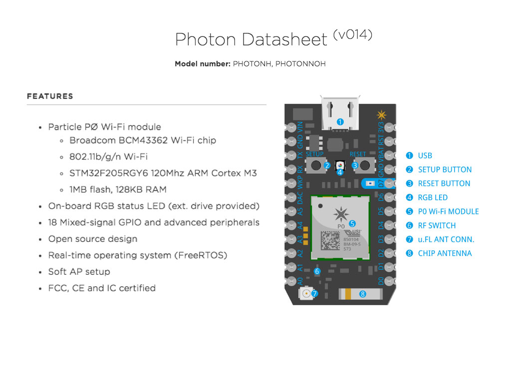
Photon board has great compact packaging wich inludes microcontroler with buildin Wi-Fi module, two antenas, RF switch RGB LED, setup and reset buttons.
It works with 3.3VDC and with 5VDC sources and gives output about 5V. There are 8 digital pins and 6 digital/analog pins to work with.
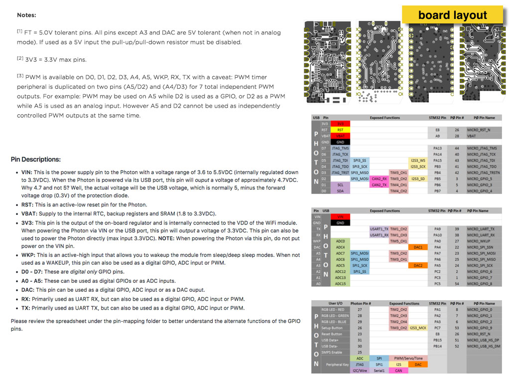
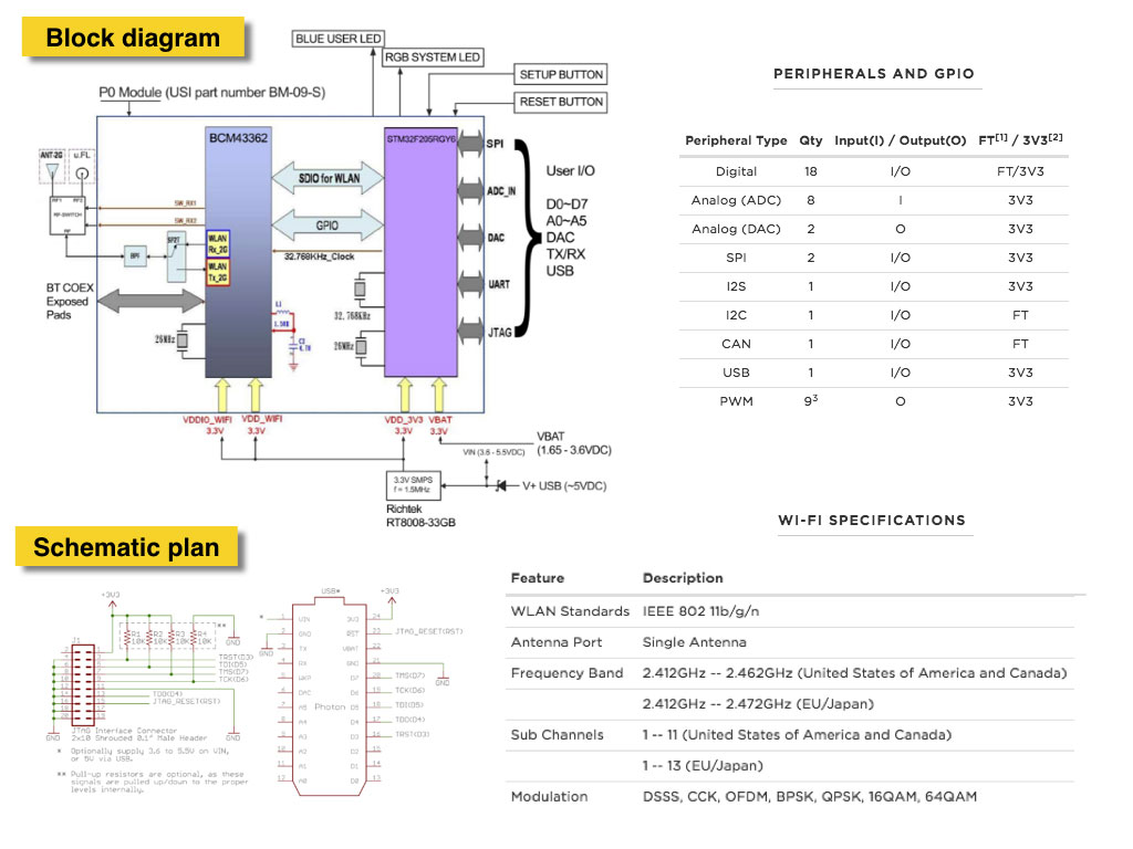
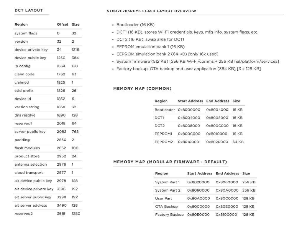
Power layout and Memory map
I started with simple target - make the LED blink.
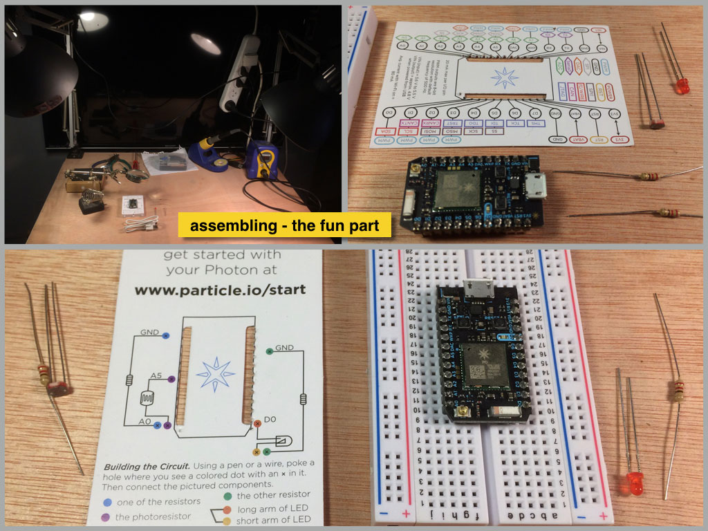
First I assembled the components on the bread board as described. Downloaded and installed client regestration for web browser IDE.
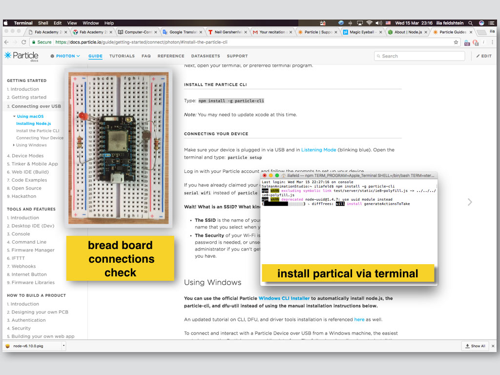
Next I pluged the board and started to write the code. Blinking with LED was very simple task. All the programming process happens in cloud. That makes some sence for IOT, because at the very next step I acomplished to turn on and off the LED from web page. I was also able to control the LED through terminal commands.
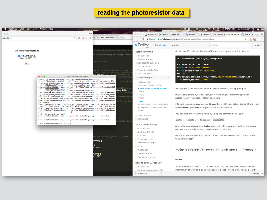
Not only LED control was easy with PHOTON, I succeeded to read the LDR data from the web. I turned the LED on and of and checked the analog input from the photoresistor after each switch. I placed both of the components on the bread board close to each other and I bended them one toward other to aim the LED light directly in to the LDR. This way the differences in LDR mesurements between LED ON and LED OFF positions were recognisable even during daylight.
As part of my alternative platforms research I experienced another input/output process.
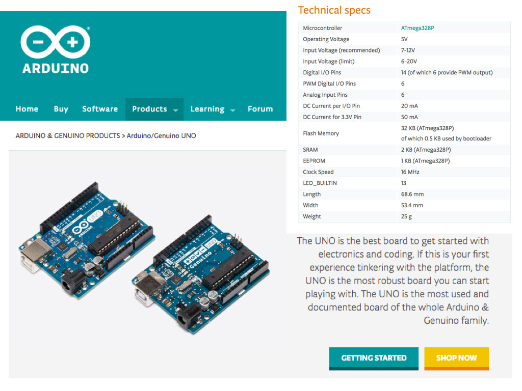
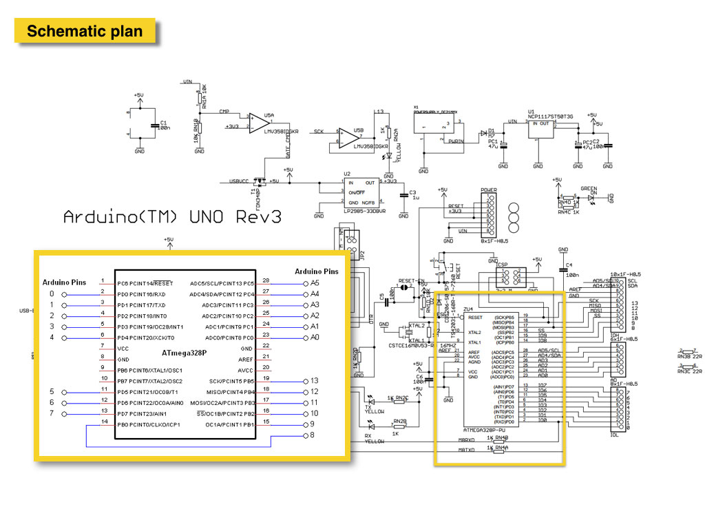
This time I used Arduino Uno board.
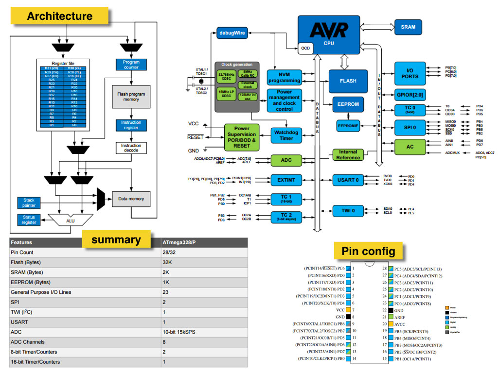
Board diagram and schematics.
But instead of blinking LED output or button/LDR input I decided to try something new for me: open source developed commertial pulse sensor.
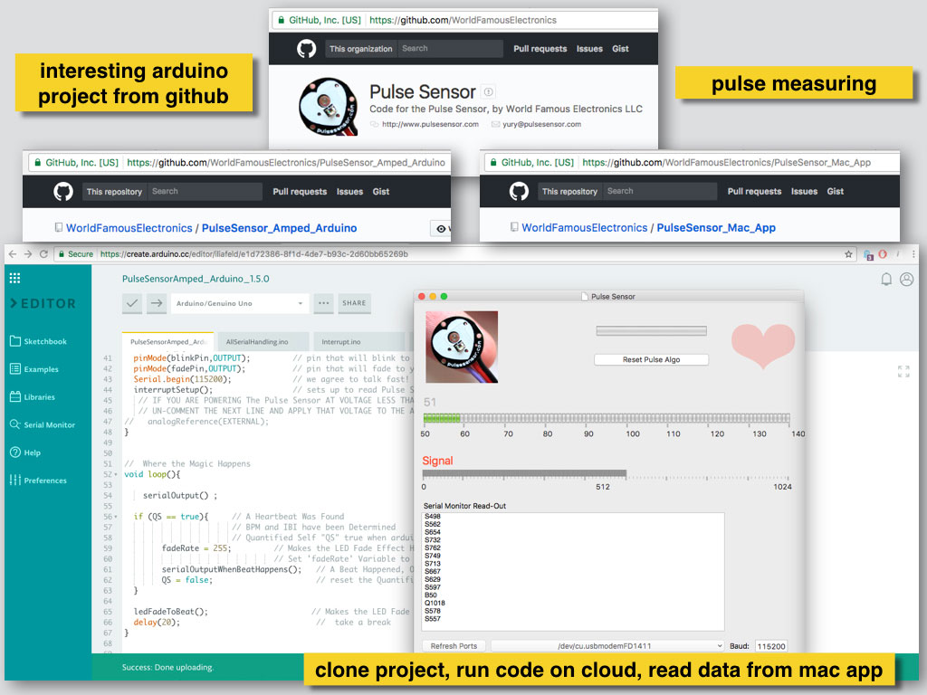
I followed the steps from the project Github tutorial and it worked also pretty smooth.
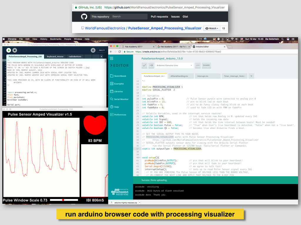
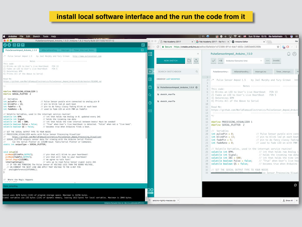
Pulse sensor developers provided free Mac app with data reading interface and also Processing GUI program as serial plotter output. It means to that two softwares at least had to run simultaneously to represent the data. That is how the Arduino web IDE workflow forced me to work. The browser IDE lacks of basic tools like the Serial Plotter. At this point I decided to download local Arduino IDE and to try code modifications.
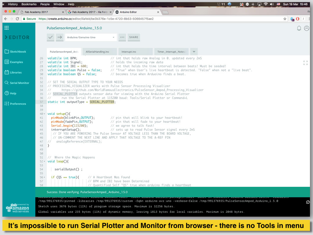
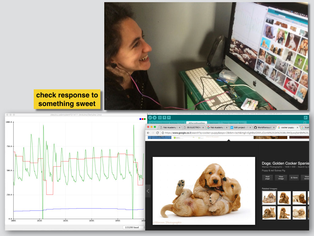
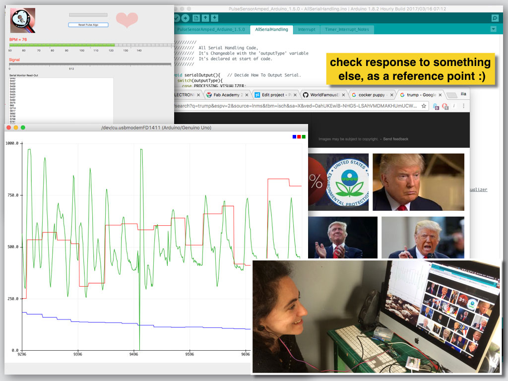
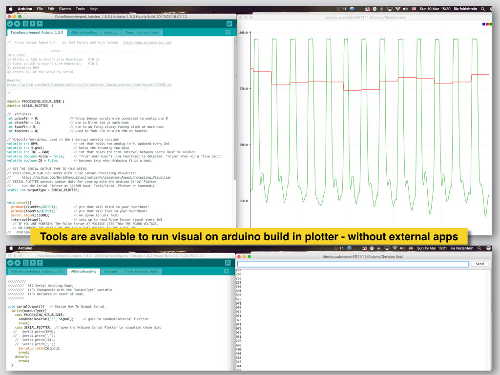
I changed the Serial Plotter output definitions in the original code in purpose to send the sensor input data to the build in Arduino IDE Serial Plotter instead of running the Processing pulse visualizer in parallel.
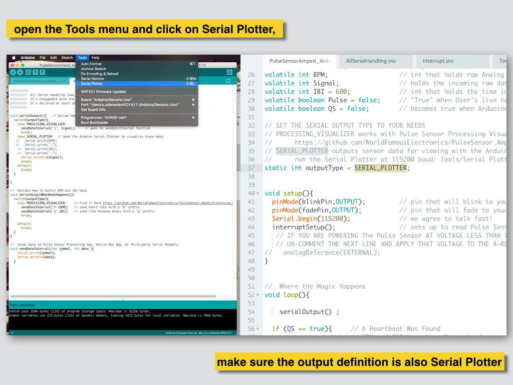
Serial Plotter window must have the 115200 baud setting to read the sensor data.
For correlation test I used my friend and two sets of images. The idea was to check the emotions effect on the heart beat.