Week 6:
Electronics Design
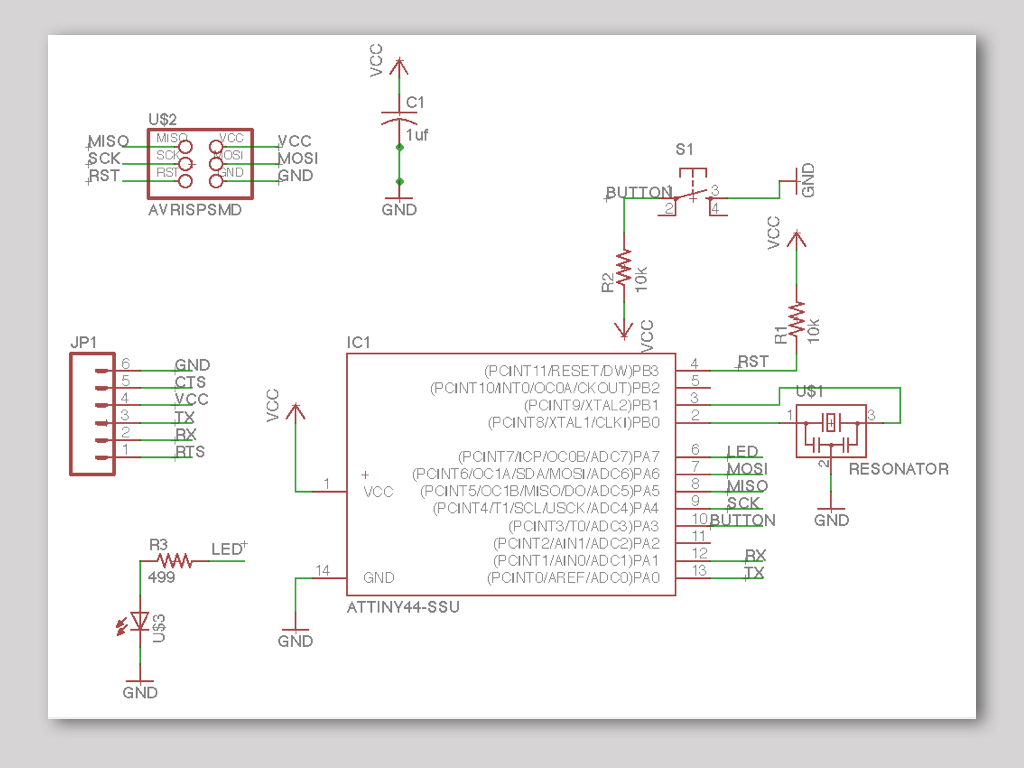
The goal is to add LED and button to existing
"hello.ftdi" board layout.
Board design
Download Eagle software from Autodesk site.
Open Eagle, go to FILE menu - NEW - PROJECT. Give it name.
In Eagle control panel, click right mouse button on you new created project and choose NEW - SHCEMATIC. Here you will set only the logic, how it is connected and not how the board will look like.
Press ADD button in side menu - choose component from fab library, press OK and locate it in schematic window, press ESC and choose the next part or press CANCEL to finish adding.
Use NAME and LABEL commands to inform about what each part and trace is.
Use NET, LINE, JUNCTION and AUTOROUTER commands in schematic to connect the parts to the microcontroler, power and ground.
Put attention to the alert yellow button in side menu. Click it to exsplore about bugs in routing, overlaping and other conflicts.
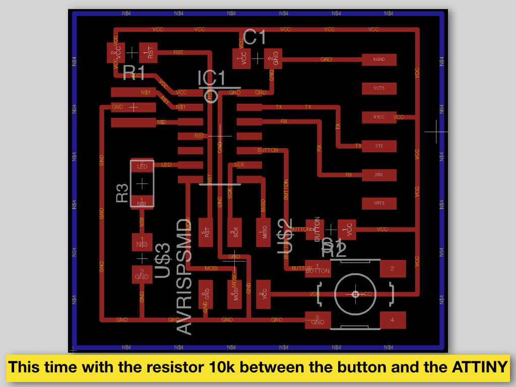
In top menu switch from SCH (schematic) to BRD(board). Here you will set/design how the board will look like.
Use MOVE and ROTATE to place all the parts from right and above the origin mark.
Use AUTO ROUTE and ROUTE commands to set the traces.
Put attention to the warning yellow button in side menu. Click it to exsplore and then fix bugs in routing, spacing, overlaping, trace width, clearance and other conflicts.
Choose bottom (16th) layer and create the outline shape of your board around the components.
In FILE menu go to EXPORT and choose IMAGE. Give it name and location, set resolution to 600 dpi MONOCHROME. DO it separately for the top (traces and pads) and the bottom (outline) layers. You should get this way two PNG files, one for traces and pads milling and second for outline cut out milling.
Exporting PNG and Milling PCB
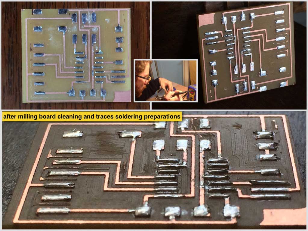
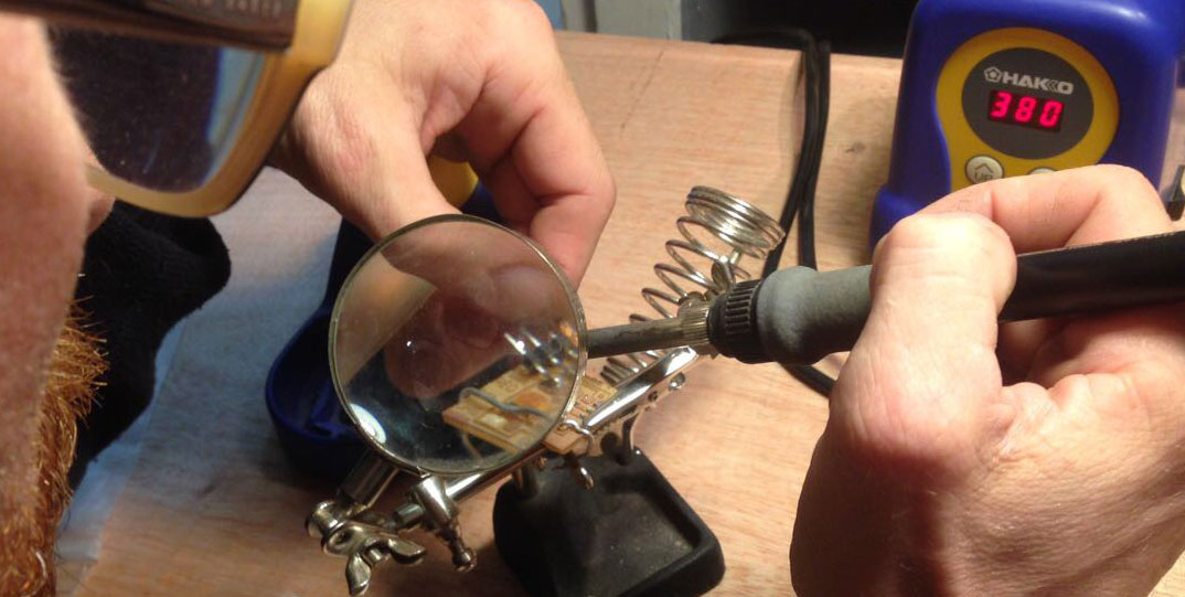
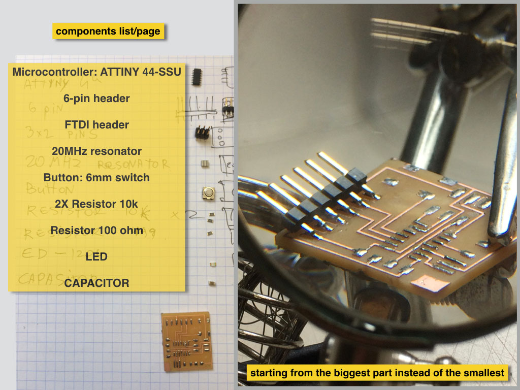
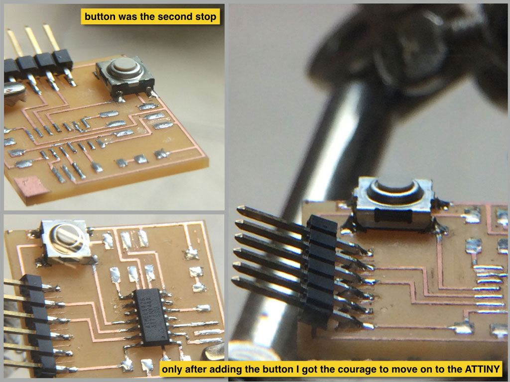
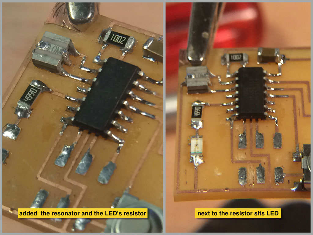
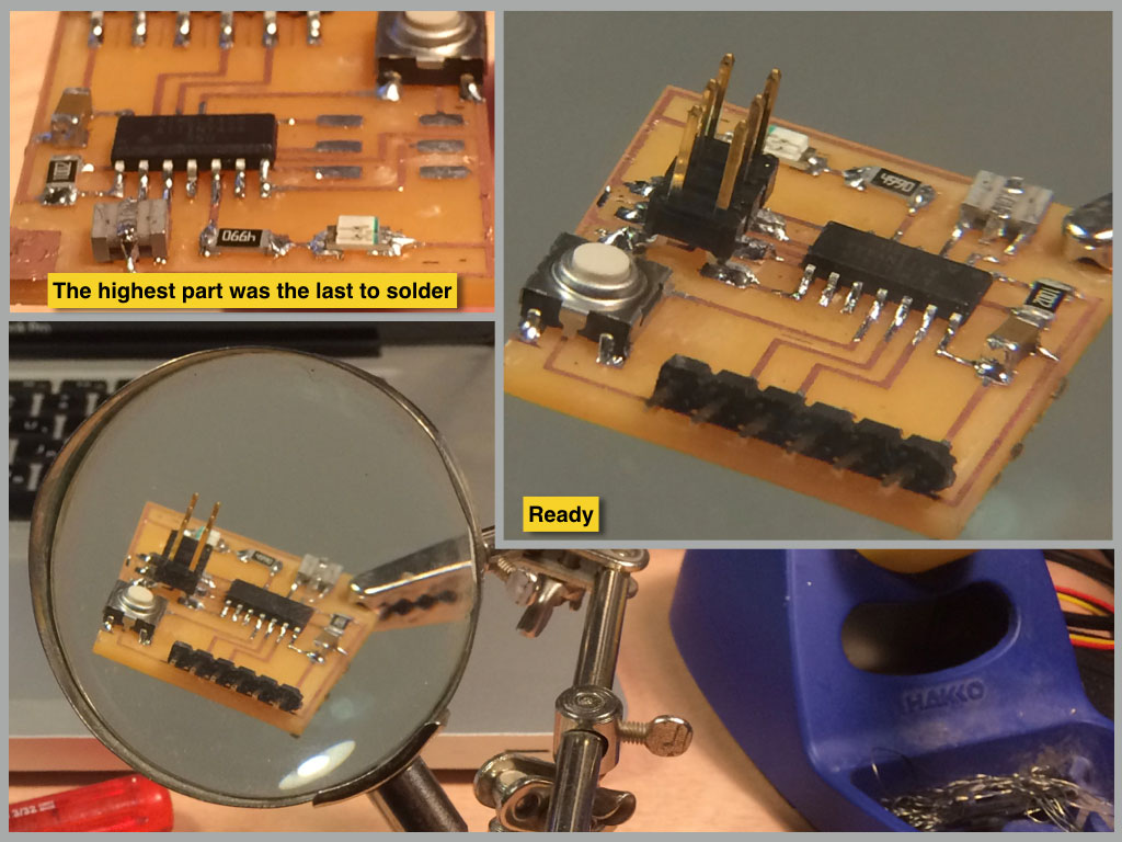
Soldering
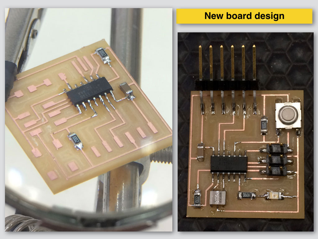
It isn’t recommendable to start as I mistook to start with biggest part of the board.
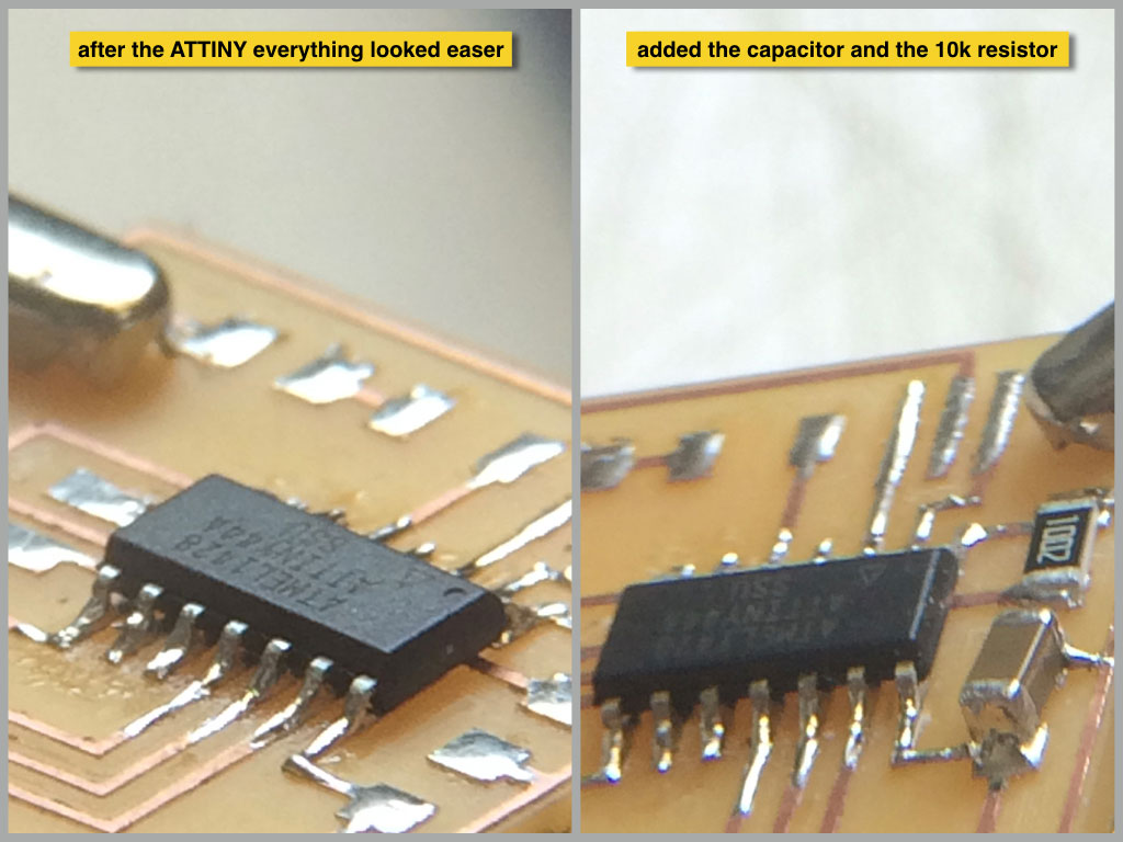
It is easer to start in the center with the ATTINY and to continue adding parts around it.
That is how the work space of soldering head gets more freedom in angles to approach the heating points.
Programming
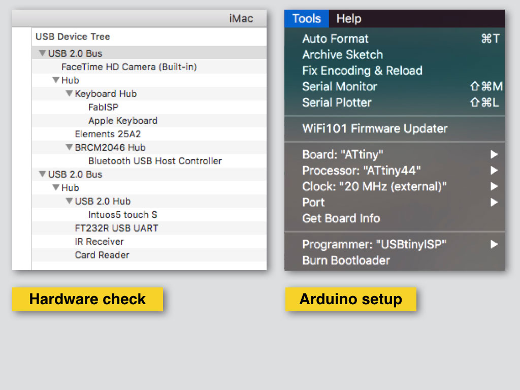
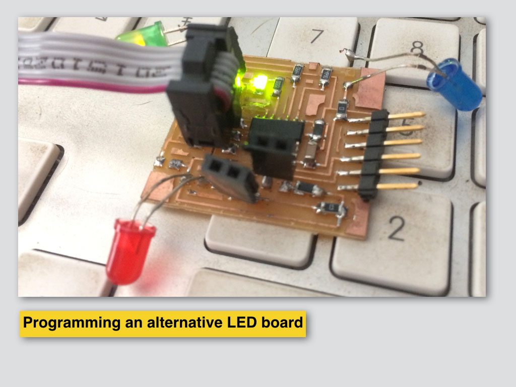
Programming the LED and button board with FAB ISP in ARDUINO IDE.
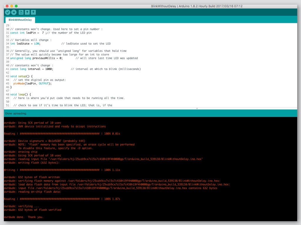
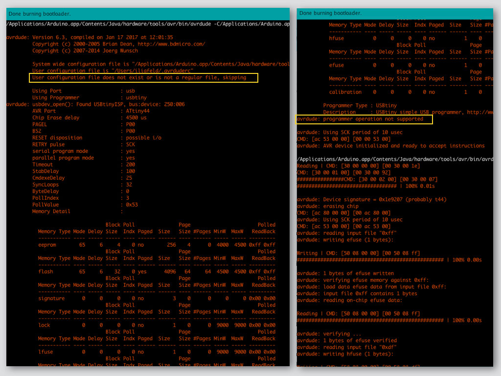
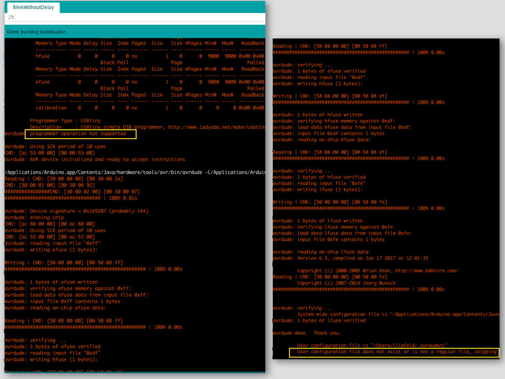
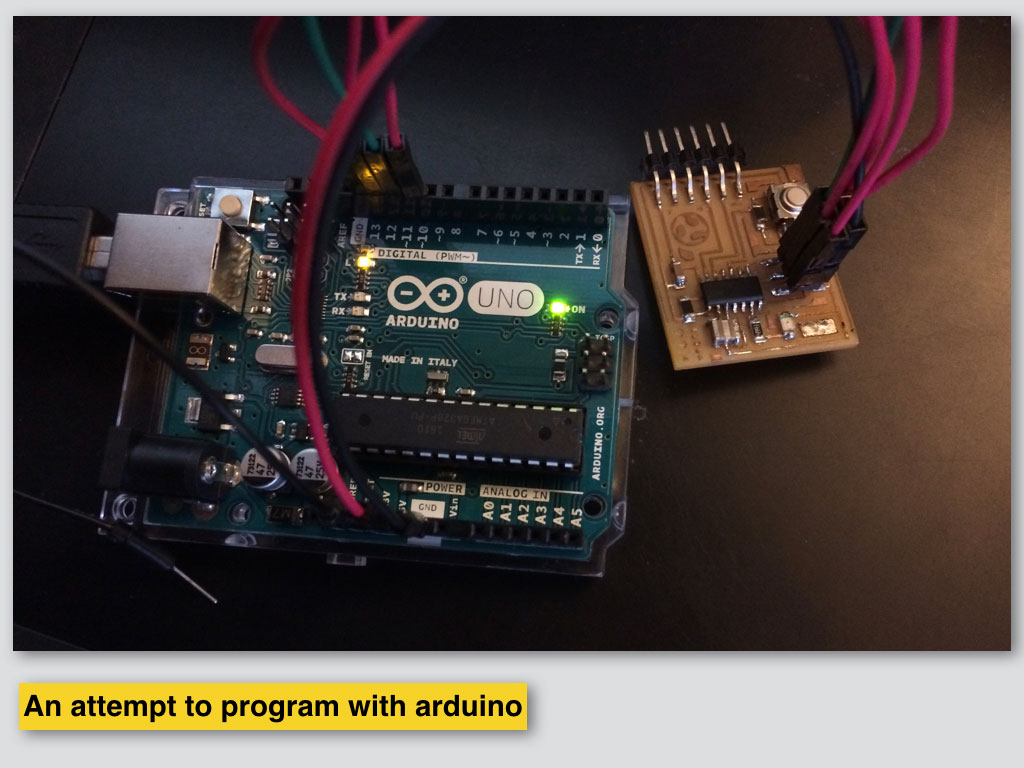
Here I am trying to check my workflow with some other USBtiny programmer and alternative board that has LEDs just make sure the process is correct. This time I had fortune with me and seems that the worflow is right.
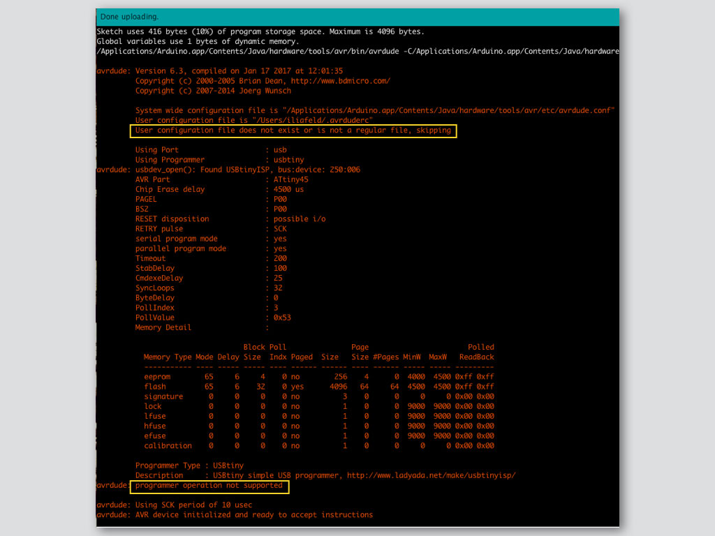
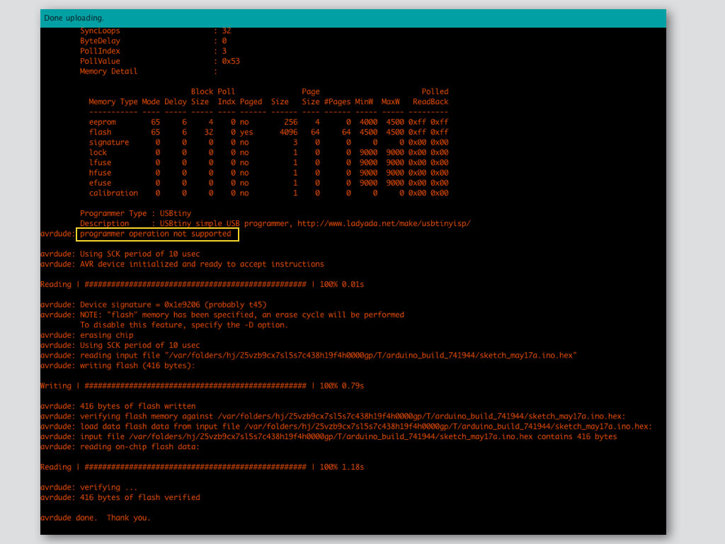
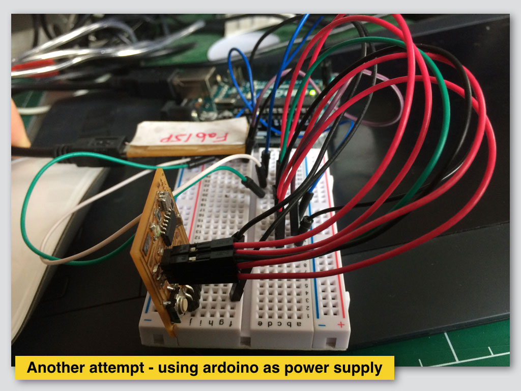
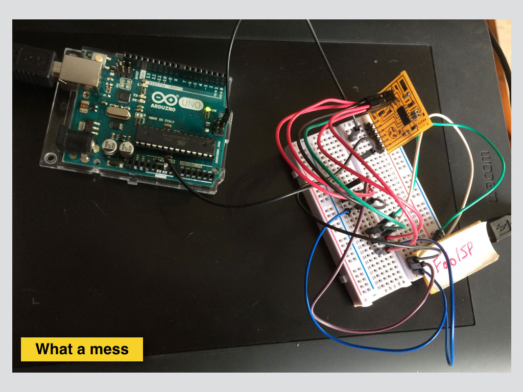
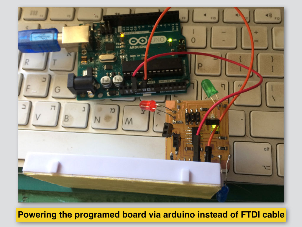
In following image and video I show usage of Arduino board only as power source the LED board I programmed.
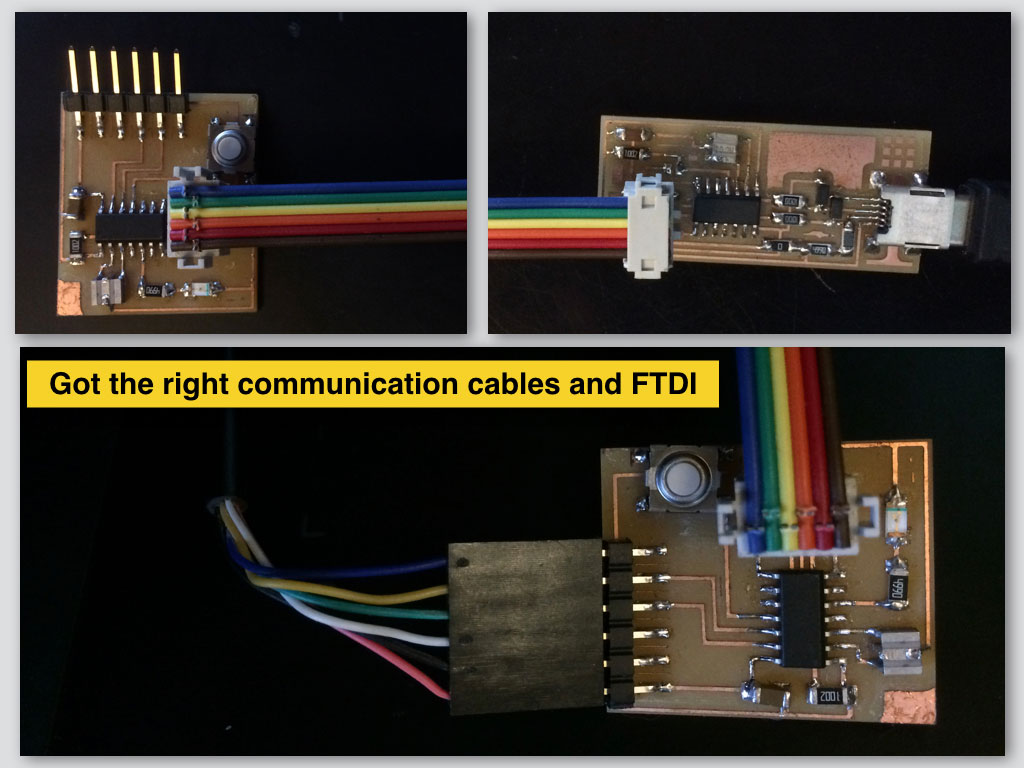
After first unsuccessful board, with the missing part I created a new one which worked perfectly.
Logic
Design
Fabrication
Programming