Week 7:
Computer-controlled Machining
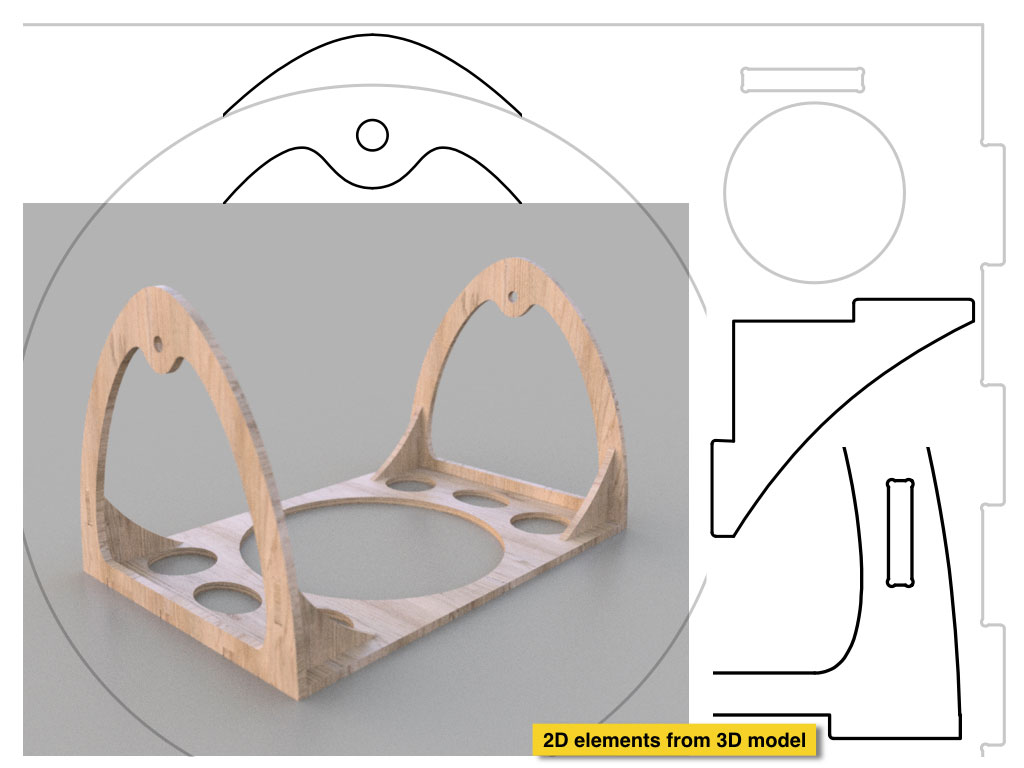
Modeling
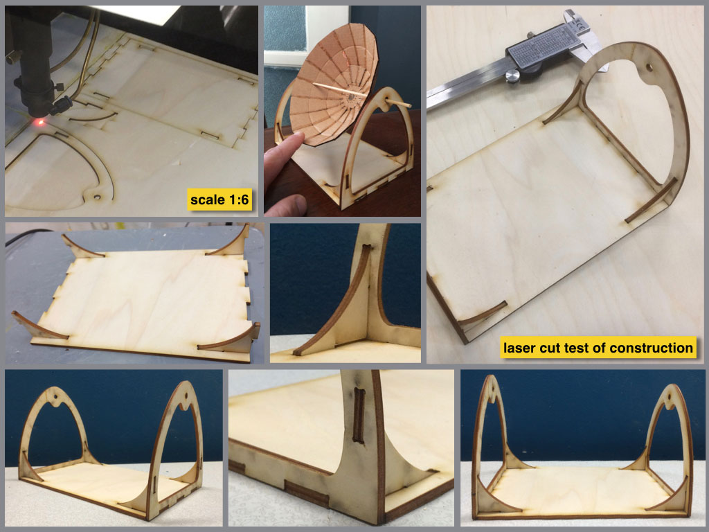
The focus in this fabrication process with CNC is at the biggest part of my final project. The plywood structure will be placed on motorized rotation base and will turn during the sun tracking. The second turnable axis for parabolic mirror will be placed between two holes on the structure walls.
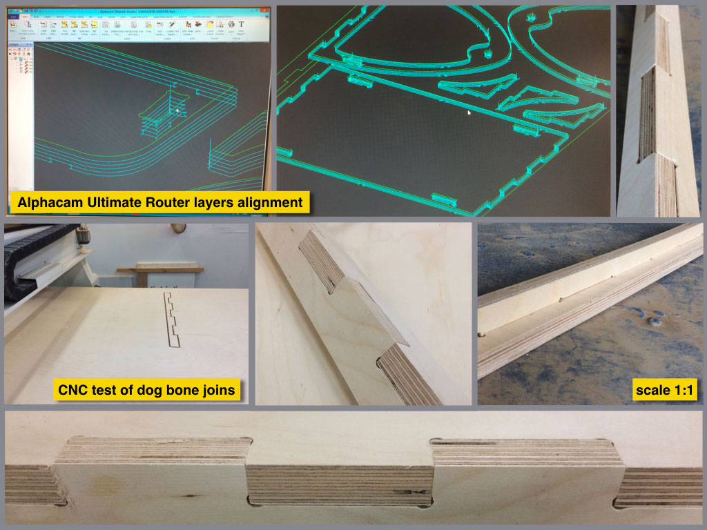
Files preparation
Press-fit constructure
Scaled test
Laser cut test 1:6 scale
1:1 CNC test
CNC 1:1 joint test
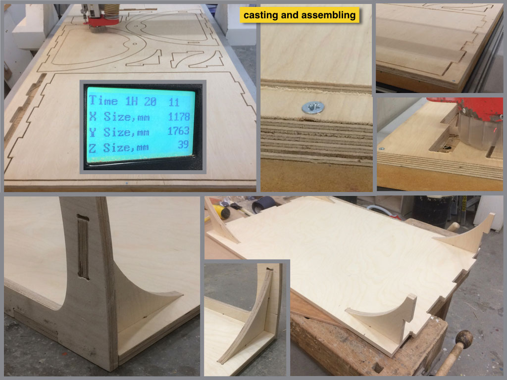
Fabrication
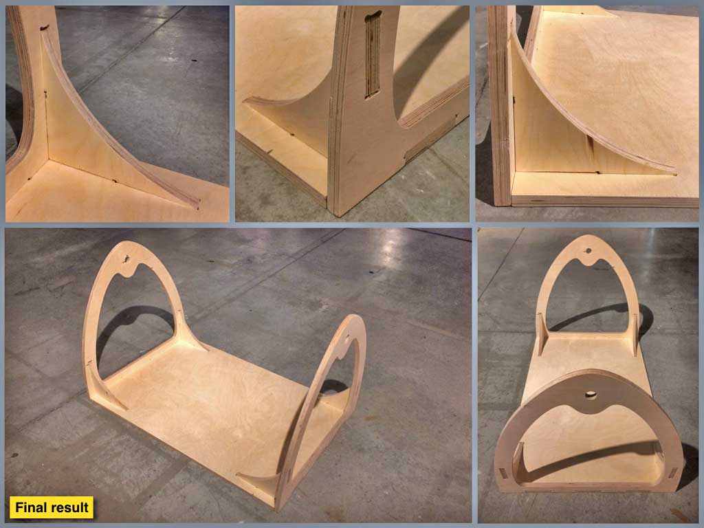
Final result