Week #2 Computer-Aided Design
Assigments
Software Used
- Fusion 360
Machine Used
- Not yet
Exercise Repo
You can find all files used in this class in the Fab Academy repository in the button below or a backup in this Google Drive folder.
Past experience
I learned how to modeling in a CAD software while sophomore (in the middle 2nd semester), in a course called 'Technical Mechanical Design II' (during the 1st semester we did all designs by hand). At that time we used Solid Edge, but we didn't really design, we were just copping, transforming 2D design (we received printed sheets) into 3D models. Since that course, we were never more requested to produce a CAD file. We did have a lot of more mechanical courses, all theoretical. In 2015, after come back from OSE, I start practicing modeling. I was using SketchUp and Tinkercad. Past year I start practicing Fusion 360, since it is the software planed to be used in the course I teach at Insper.
What you will see in this assingment
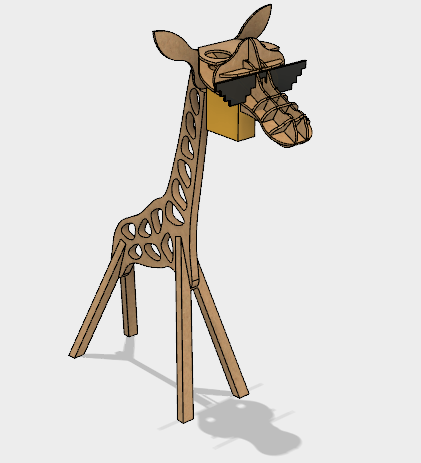
This assingment is organized in two blocks. The first one is related with my final project, a Giraffe Lamp. It is divided into 3 modules: Head, Body, and PCB holder. The picture bellow shows this project overview, and following topics describe how each module was designed. The second block shows the early design of my first idea for a final project: a indoor composter machine.
Giraffe Lamp
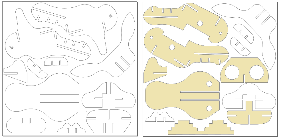
To fit my final project purpose, the plan was to build each module of the Giraffe Lamp using a different process. The Body is designed to be made by CNC milling, the Head by Laser Cutting and the PCB holder by 3D Printing. The design of each module is described bellow.
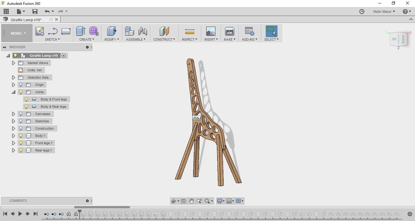
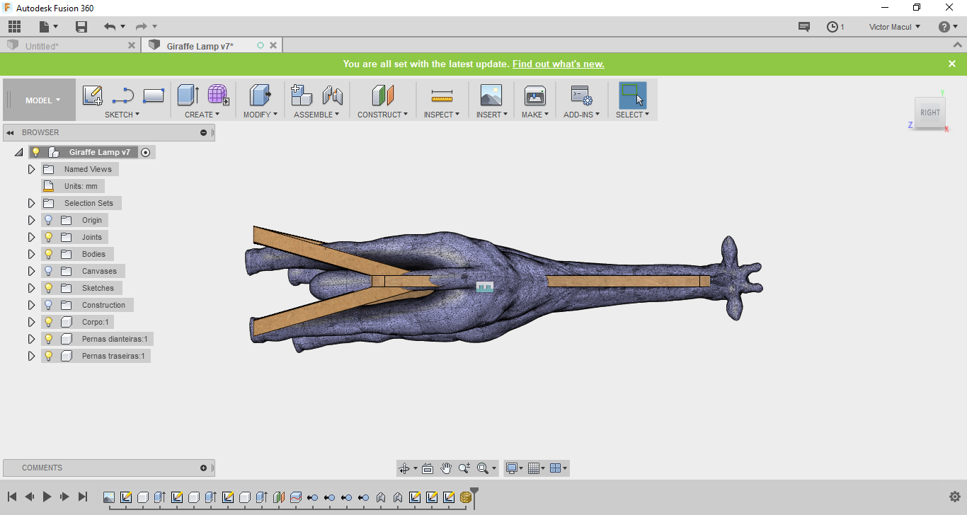
Giraffe body
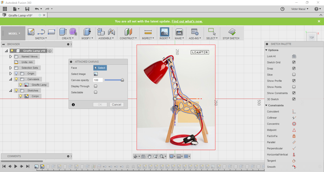
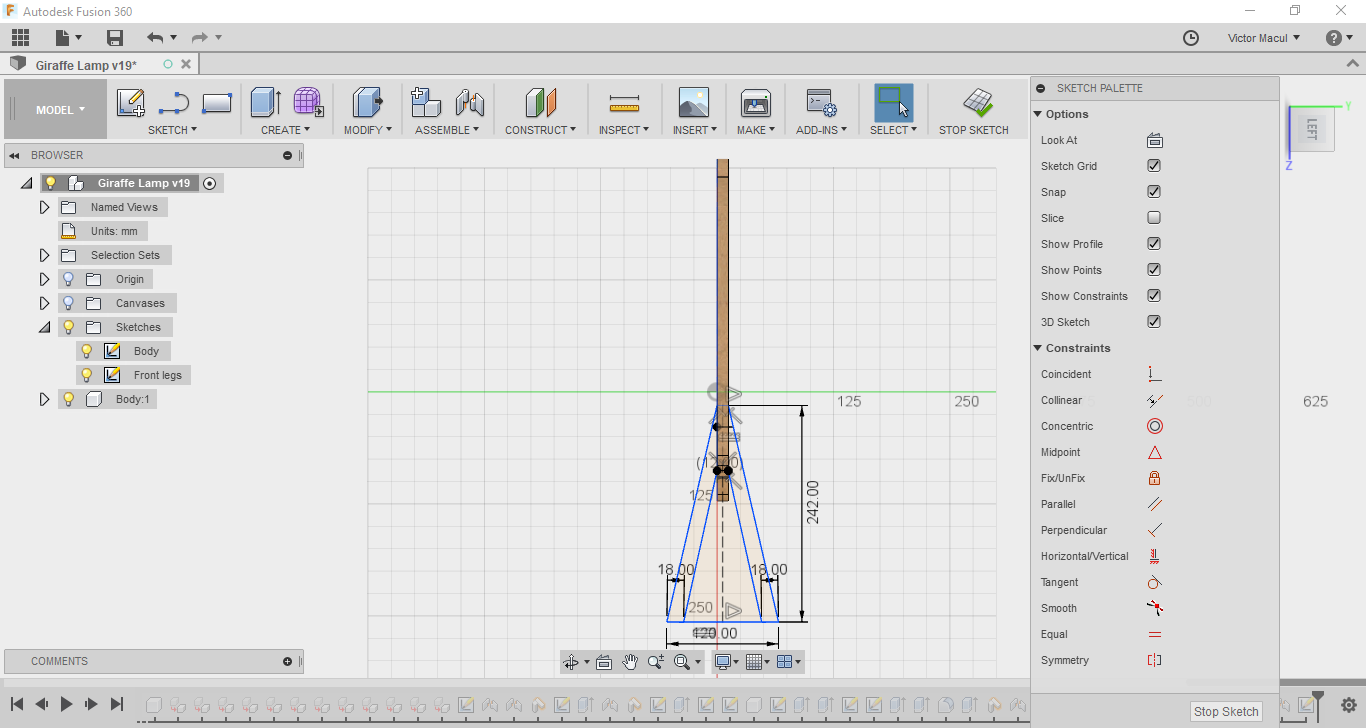
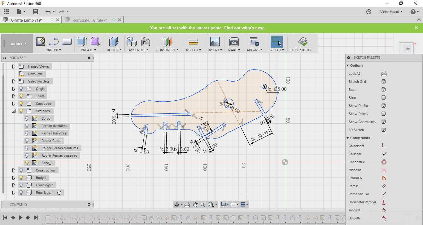
I started modeling the giraffe head in Fusion 360, using as reference an image that I found on Petit and Small website. I did it by ataching a canvas (Insert > Atached Canvas). With the body done, I use it as reference to design the legs. By doint it, both legs were at the right position to be assembled. I did it using the As-built Joint (Shift+J shortcut) feature. The pictures bellow show this process.
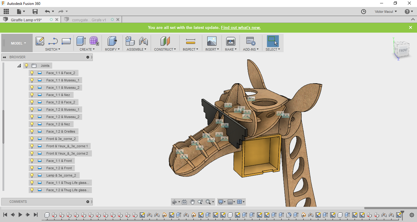
Giraffe head
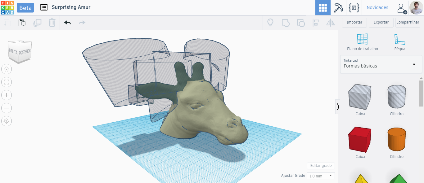
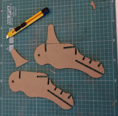
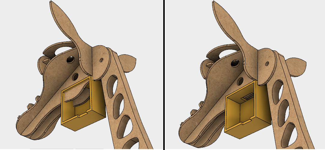
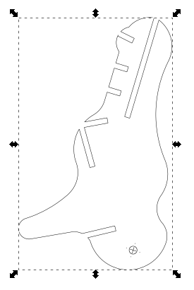
I started modeling the giraffe head in Fusion 360, by an stl file that I found on Thingiverse, made by YahooJAPAN. My initial idea was to model it to fit in the body I had designed and then use Slicer to make the shapes to cut on laser cutting. But, I has having some difficults in dealing with a mesh on Fusion. I could not found a way to transform the stl file in a solid. For this reason, my next step was to use Tinkercad to model the stl in the shape I wanted, but because of its curves was not so easy to work in it in the Tinkercad too. While looking for more files available online to use as reference, I found a perfect one on Grabcad, made by technomer on Solid Works. It was designed for laser cutting, exactelly what was looking for. I just had to import it for Fusion and adapt to my project. A good amount of work but, but much better then start form scratch. The pictures bellow show this process.
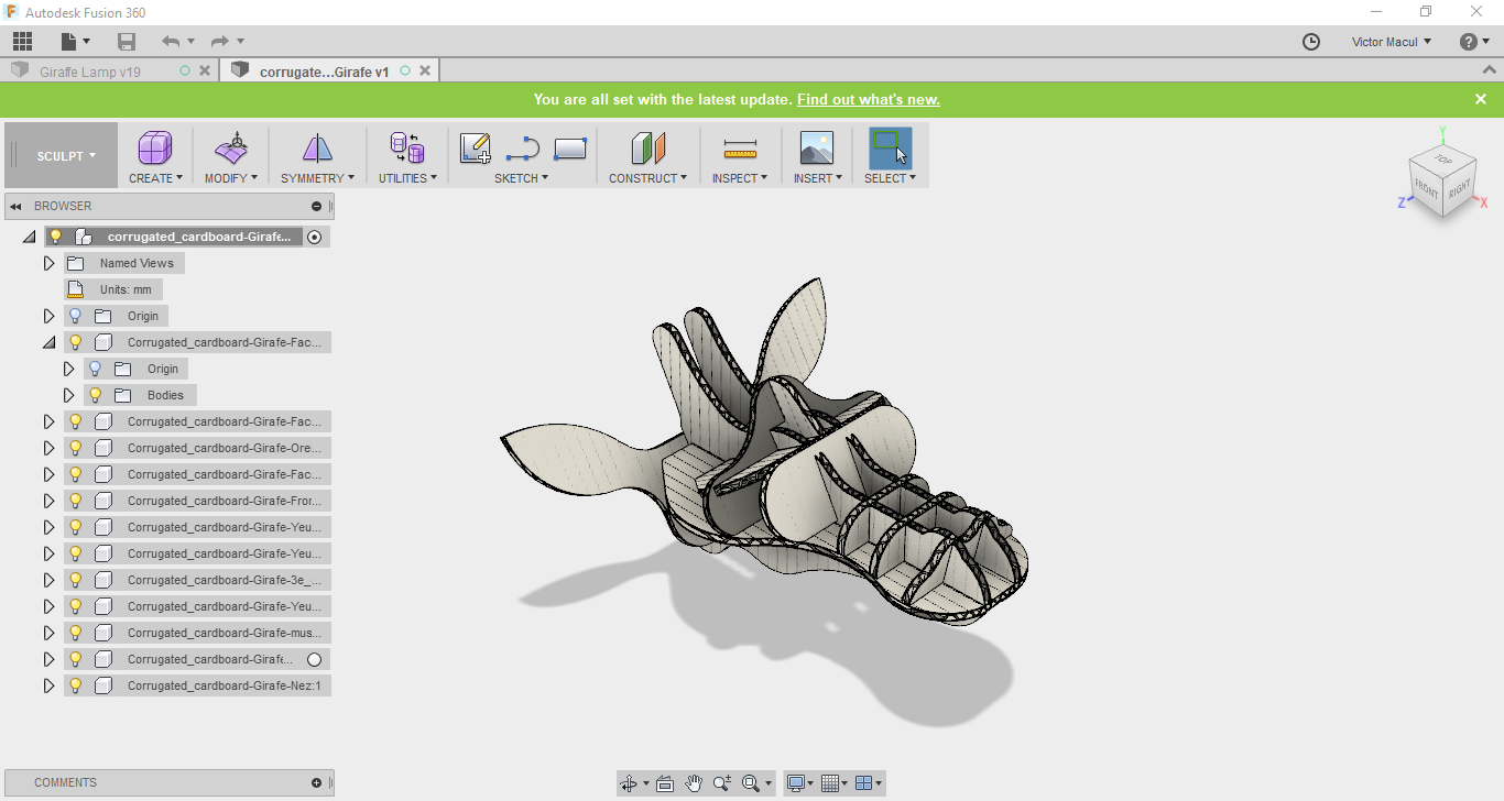
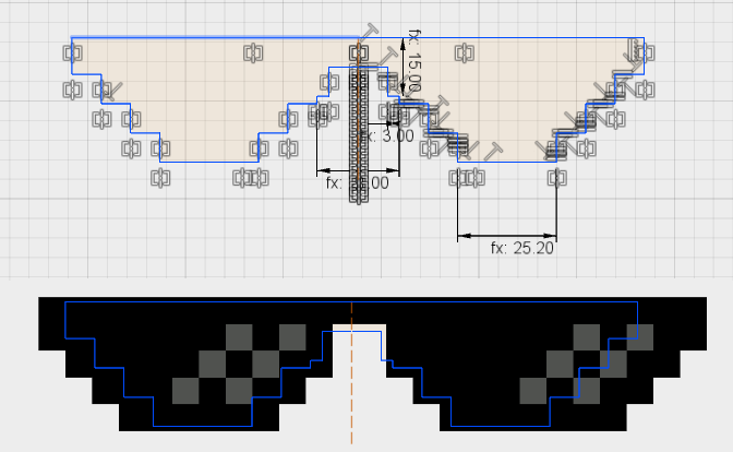
To facilitate components editing, after import the solid work files on Fusion, I exported each one faces as dxf and open it as a sketch in the same file I had designed the Giraffe Body. After that I added some constraints and dimensions to them, using parameters when possible to facilitate further changes. I designed it in a iterative process. Modeling, prototyping, testing and modeling again to make some adjustments. I did it few times before get in the final design. Sometimes making the integration in a virtual prototype, sometimes making it in the real world. My goal was to change the design to be made of a 3mm MDF sheet (the origial design was made for 4mm cardboard sheet), fit the lamps, the PCBs and wires and also make something cool for students (for this reason I did the Thug Life glasses).
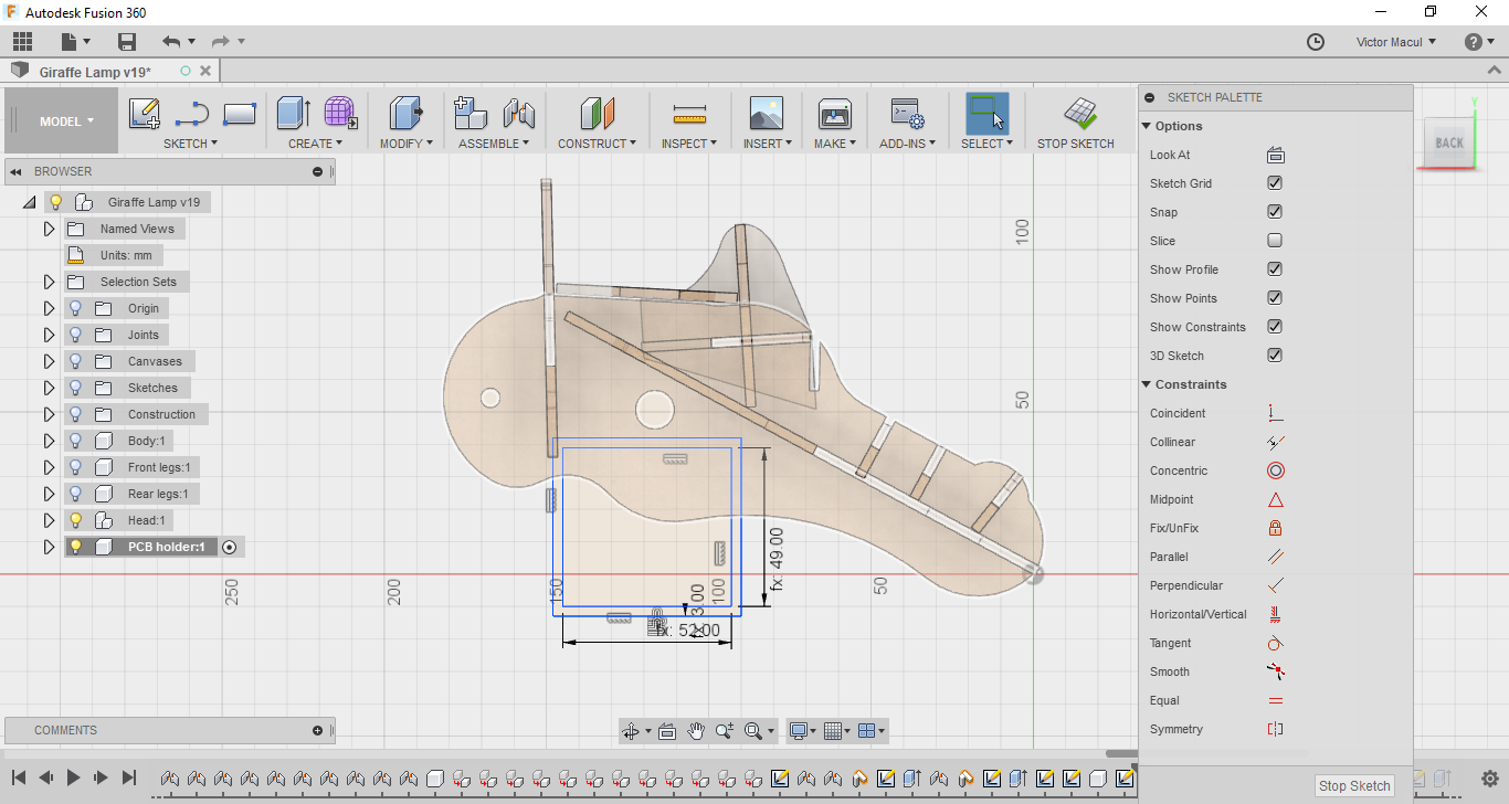
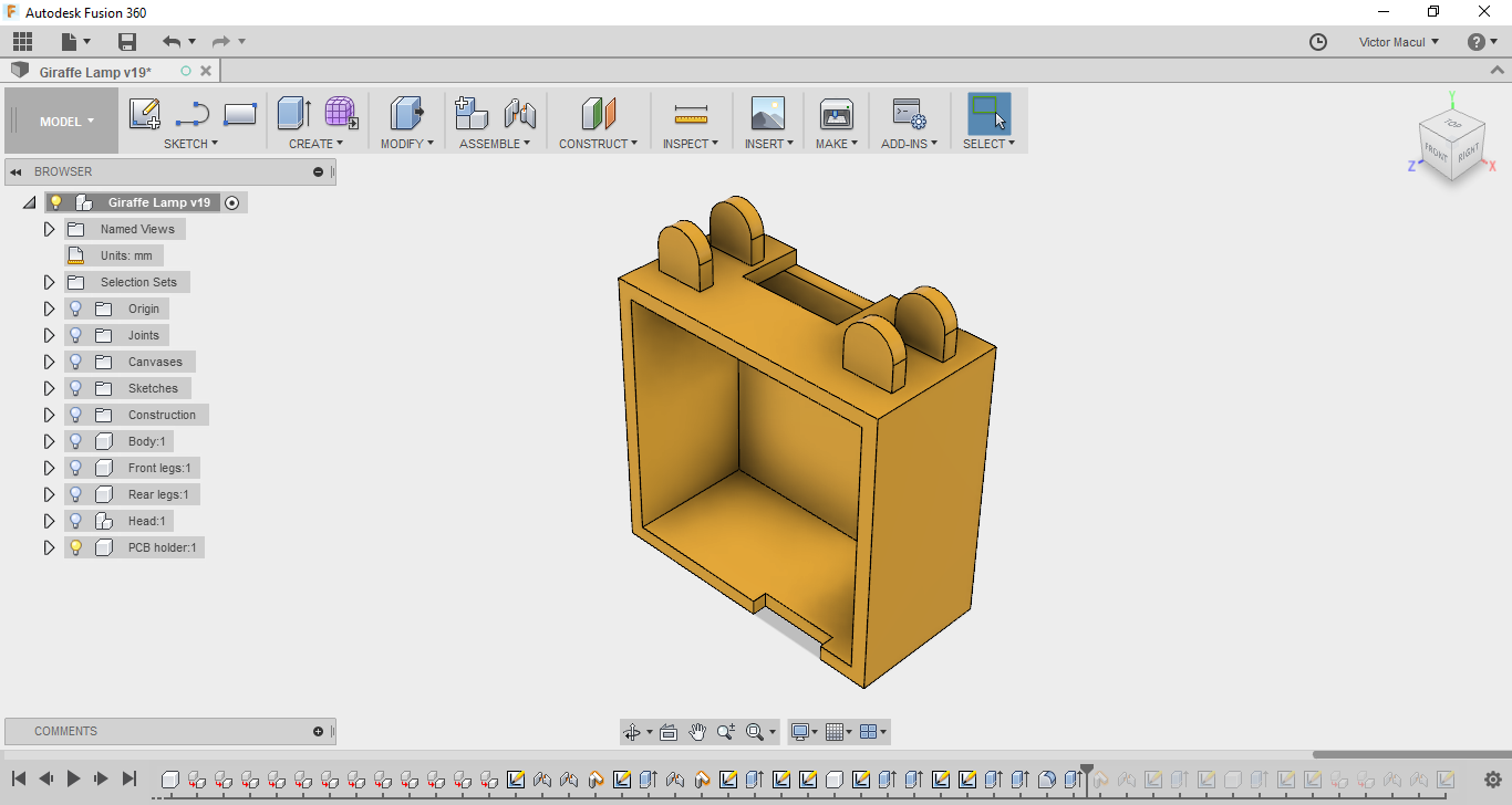
PCB holder
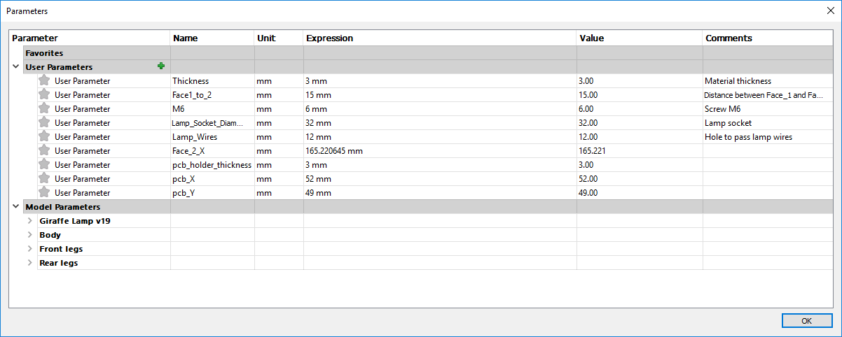
To design the PCB holder, I took some dimensions from my PCB and included it as parameters on Fusion 360 (showed in the picture above). Then I created a sketch plan above the component Face_1 to use it as reference. I did some assembles to test virtually the integrations with other modules. The pictures bellow show this process.
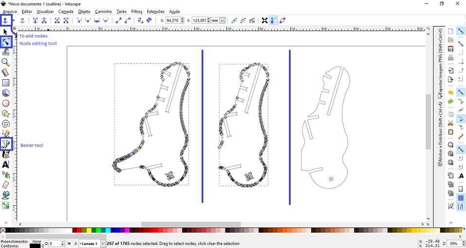
Using Inkscape
For the Exercise 03 I used Inkscape to prepare the files for laser cutter and to draw the sticker for vinyl cutter. Most part of the features I learned from Inkscape Tutorials for Beginners, by SimpleTutorials.net. In this section I will describe the features I found the most important for Computer-Controlled Cutting and 2D Design.
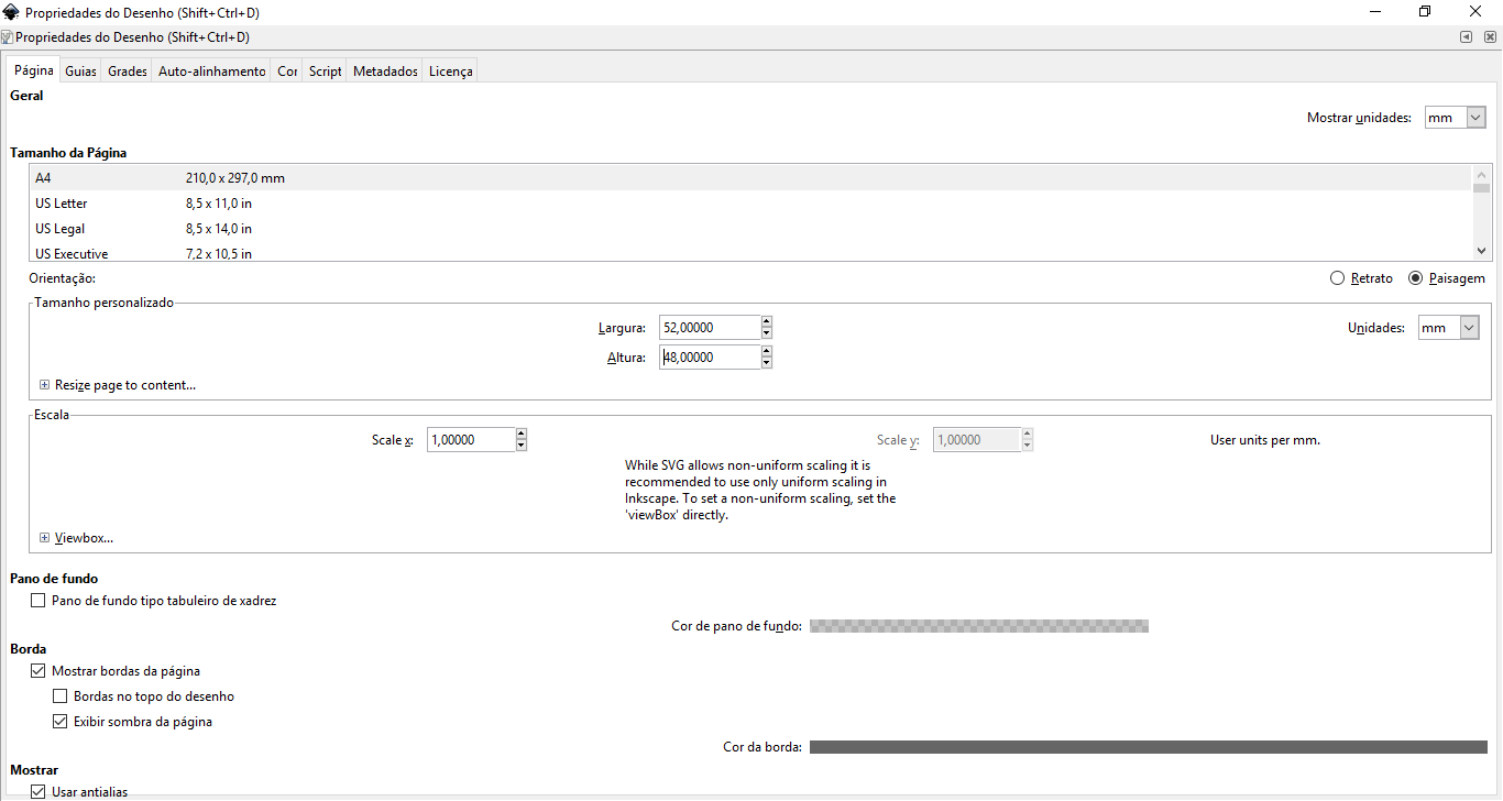
Setting canvas size
Use Shift+Ctrl+D to open the Draw proprieties window. In the this area you can change the canvas size. Pay attention to verify the unit before set the size.
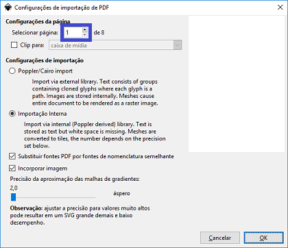
Importing an object
Use Ctrl+I to import an object. If you are importing a PDF, we can choose the page that you want to import.
Ungroup an object
Select the object and press Ctrl+Shift+G couple times to ungroup. Then you can select the parts that you don't need and delete them.
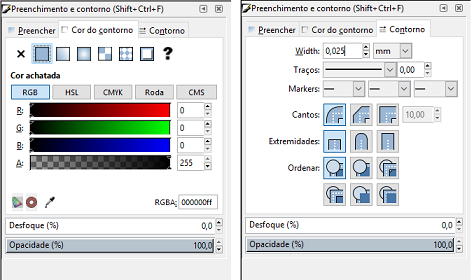
Changing the thickness and color of lines
Use Shift+Ctrl+F to open the Fill and outline window. In this area you can change the the color and the thickness of the line in its correspondent tab. Remember to verify the unit before set the thickness. If you use a small thickness, you object will probably disappear. You should activate the wireframe view mode to make it appear again (View > View mode > Wireframe).
Combining paths into a compound path
Select the object and use Ctrl+K to combine paths. Before do it check if you don't have duplicated lines in your object. Select a line and delete it, if it do not disappear is beacause you have it duplicated. YOu can also noticed that when you have a dulicated line the path will have a stronger color. Duplicated lines will make the laser machine cut it twice. If delete the duplicated lines and combine the paths, you will save time and energy on laser cutting.
Using bezier and node editing
To modify an object in Inkscape, I found very useful the Bezier feature combined with node editing. Using this its possible to divide a path in a lot of nodes and make straight lines and curves to connect them. You can also select a segment and delete it. The following tutorials show how to use this features in different ways: Inkscape Bezier Tutorial 1 and Inkscape Bezier Tutorial 2, by SimpleTutorials.net.
Indoor Composter Machine
2017 02 04 Creating 3D Model from scratch
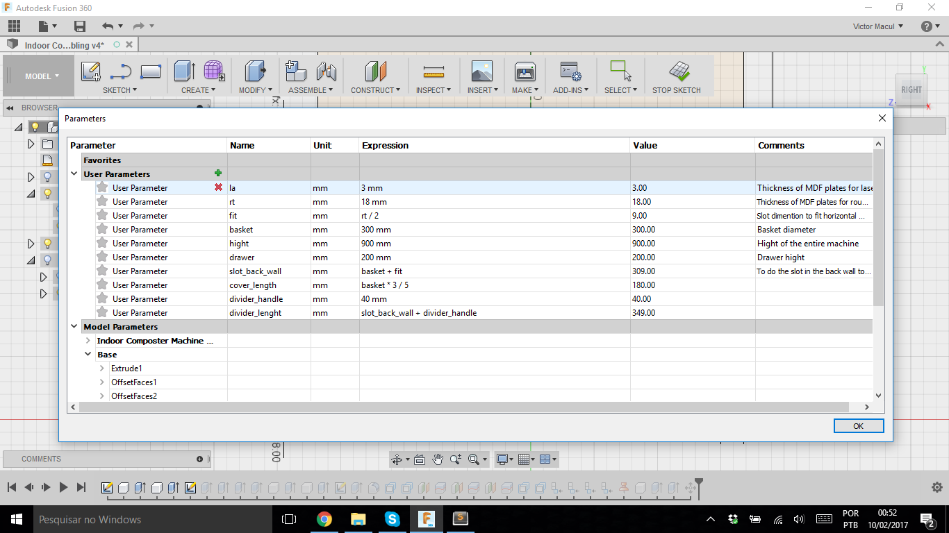
In this week I could be much more familiar with the software commands, features and shortcuts. I decided to start modeling my final project. It was very nice, because the intent to design something made me explore more features, and doing it more than one time (while testing different design alternatives) made me go for shortcuts and mouse commands, like: R, T C, Q, E F, D, "right clic" + "to draw a vertical line point up". I also decided to explore parametric design, and I search for a similar 'parameter table feature' that Neil presented during the class. And I found it on Hackaday. Then I used it.
I modeled the frame, thinking of making it on a CNC Router (this is why I uses the 'rt' parameter) and the cover, thinking of making it on a Laser Cutter. It's so nice to see how the design changed compared with my first skatch.
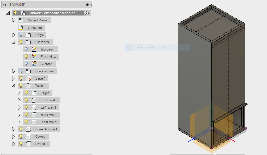
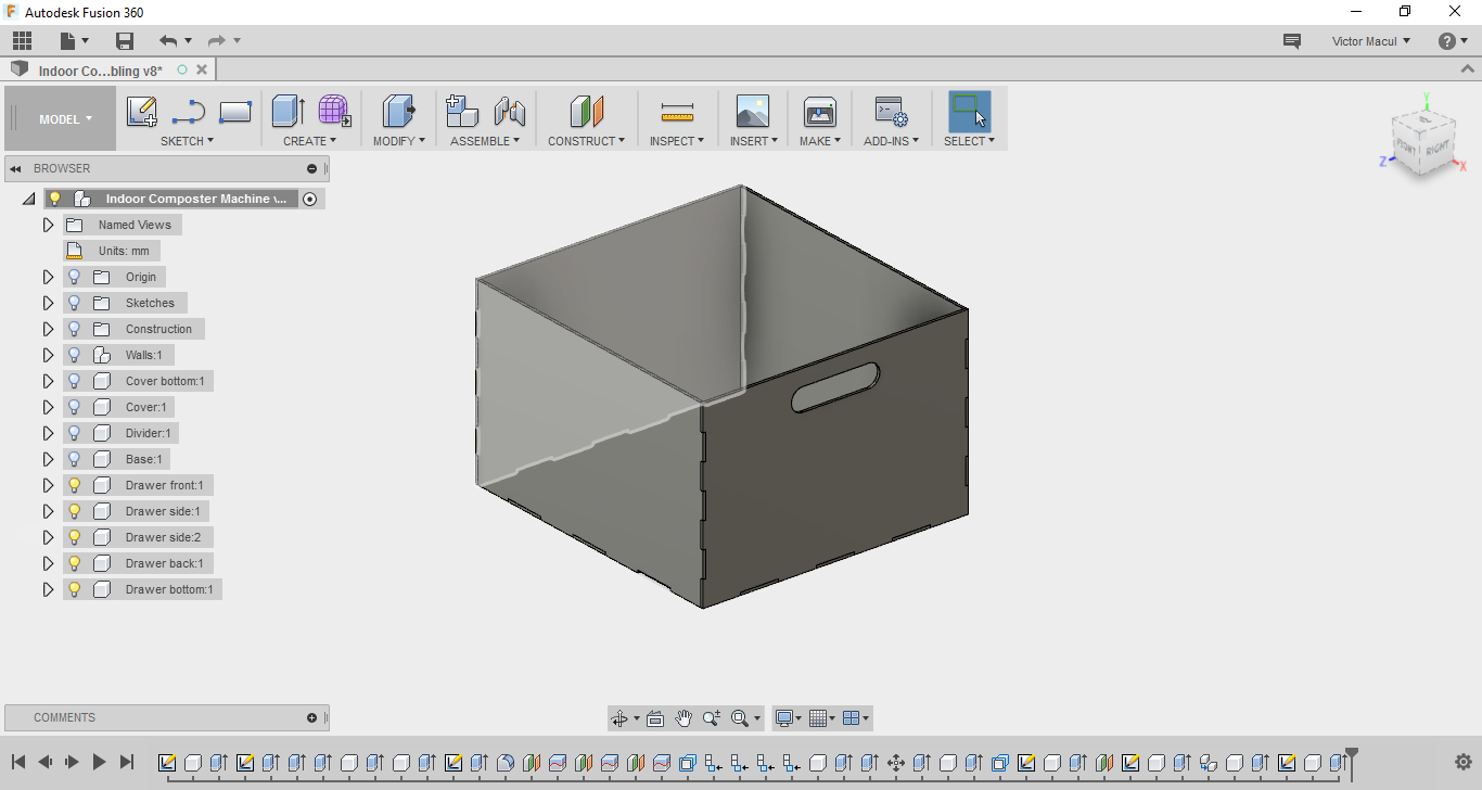
To help me think about the composter design I did the Functional Model for the machine. For particular functions of the frame I rapidy skechet some alternative solutions by hand before model in the CAD software. In the image, it's possible to notice that I've created a component for each part, following Fusion Tutorial's recomendation. I also named all components in Fusion Browser and grouped them into subsystems (like the walls).
2017 02 11 Modeling the composter drawer, thinking of making it on a laser cutter
For the exercise 03, I modeled the drawer of my machine, using a simple press-fit joint. I tried to to everything based on parametric design. And then, pop up me an issue related with the interference of the parts. As I using top-down strategy to model, I did all parts based on their interface with another parts. In this way I used the same dimensions for both. Now I'm wondering how can I set the interference between then.
Another issue that I had is related with grouping components in a subsystem after modeling them. I would like to do with the drawer's components the same thing that I did with wall's. You can notice in the picture below that all components are in the same hierarchical level (2nd). I would like to turn then in a 3rd level, below a subsystem called "drawer".