Week 4: Electronics production
Tasks for the week:
- Make the FabISP in-circuit programmer
- Program the FabISP
Task:01
Make the FabISP in-circuit programmer
This week the task is to make a FabISP in-circuit by milling it and soldering it and then programming it using the AVR to proram it.
So my first step would be to mill the board.
Step:01
Milling the FabISP
To start milling the FabISP , I first understood the method of working using Ubuntu (basics).So I documented each step of opening a file and creating .rml file for milling.
.jpg?crc=3823712711)


So after opening the fab module, select 'image (.png) for input format since we would be using the png format of the file for the ISP board. And for the output process select Roland MDX- 20 mill as the machine would take rml format for milling.
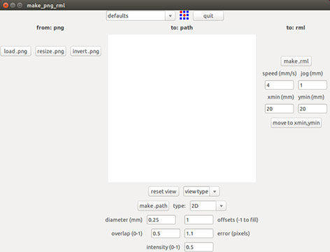
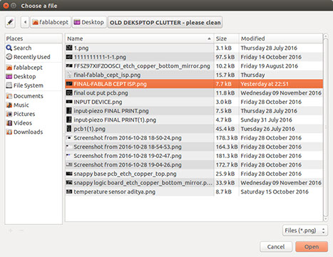
Now click on the "load. png" to load the png file that would get milled. After clicking, it would navigate to browse the file in your folders as seen in the image on the right side.


For this week, I used the FabISP that was re-designed by Rudrapalsinh Solanki (Fabacademy 2016 graduate).
The image on the left is the file that holds the connection of the various components of the ISP board. The bit I used for milling this file was 1/64" diameter. The .png file can be accessed here.
The image on the right is the file that is used to cut the outer boundary of the board. The bit I used for milling this file was 1/32" diameter. The .png file can be accessed here.
-crop-u4749.jpg?crc=49000310)
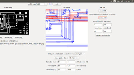
To set the parameters for the milling of the board, first thing required is to change the setting for the milling from the tab in the top-middle of the tab that says "default".

Change the default to "mill traces (1/64)" to mill the inner traces for the pcb. Next step is to set other parameters that are seen below on the tab.
-crop-u4775_2x.jpg?crc=4183921072)
-crop-u4783.jpg?crc=3852631188)
Change the diameter to 0.4 mm. and offsets to 4. Set the value for the z-movement as -0.1 because by this it would mill in depth than just milling on the surface. Click "make path" for it to make path for milling.
Note: If you keep a larger offset, the connections may become very thin while milling or may even break. Also, all parameters are in mm.

Now move to the required x and y position on the board from the tabs on the right. But before that fix the board on the milling bed. Next, click on "make .rml" to create toolpath for milling the board. Once you click, it shows an option to send the command to the machine saying "send it". Click on "send it" to send the command to the machine.
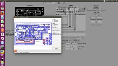
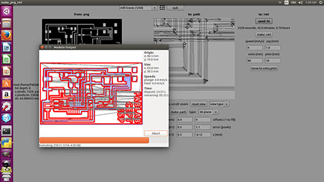
After clicking on "send it" the above seen tab is opened. Now click on "begin milling" to start the milling process. As you can see, as the bit would move forward on the toolpath, the paths would turn red on the screen.


Above images show the process of milling.
Failed attempt:
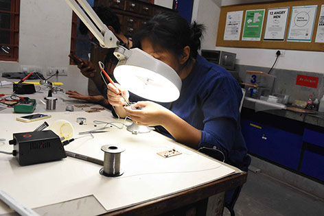

I could not do a very good job at my first attempt of soldering the components. It can be seen in the images on the right.
As the soldering wasn't proper, many placed the solder was bridging on two tracks. Also, many didn't connect. As a result I had to join them using conducting wires. My fellow student Gautam Prakash helped me understand these connections. Thanks Gautam:)
Also, when I connected it to AVR, I could get the orange light blinking but not the green light. So in all the first attempt was a total failure.
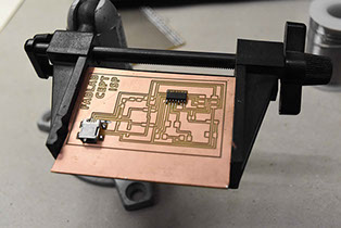
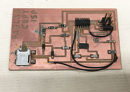
Second attempt (Successful):

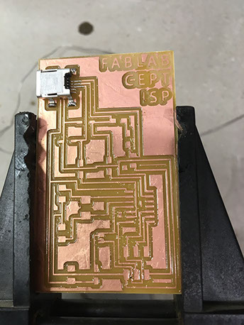

The second attempt, every component soldered properly. I moved on to my last component, the male 6 pin header and by my mistake, the track came off the board. It can be seen in the image on the right.
But , it hadn't come out completely so I went on to see if it can be programmed.
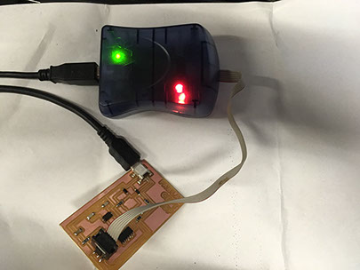
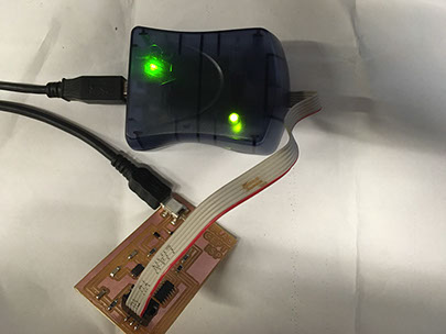
I connected the board to the AVR for the "AVR test". It showed me the orange light flashing and also the green light on reversing the pin.
Task:02
Program the FabISP
For this task, I referred to this link.
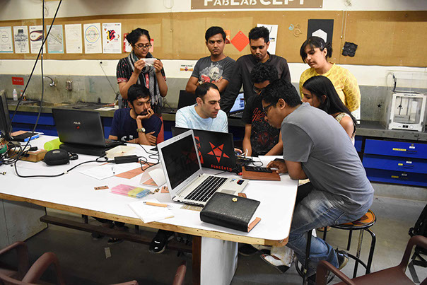
Also, this week we had Ohad Mehuyas (instructor) to guide us with programming the FabISP.
I connected the board to the AVR and to the linux pc to program the FabISP. Next I followed the steps mentioned in the link above to program the FabISP.
- make clean
- make hex
- sudo make fuse
- sudo make program
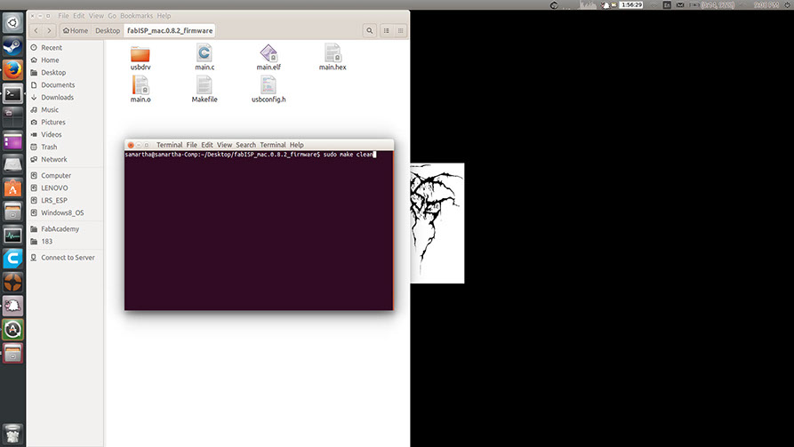
Step:01
Open terminal in the window and Type command "sudo make clean".
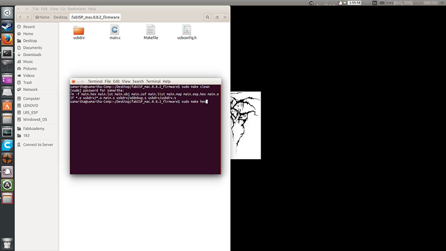
Step:03
Type command "sudo make hex"
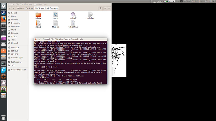
Step:04
Type command "sudo make fuse"
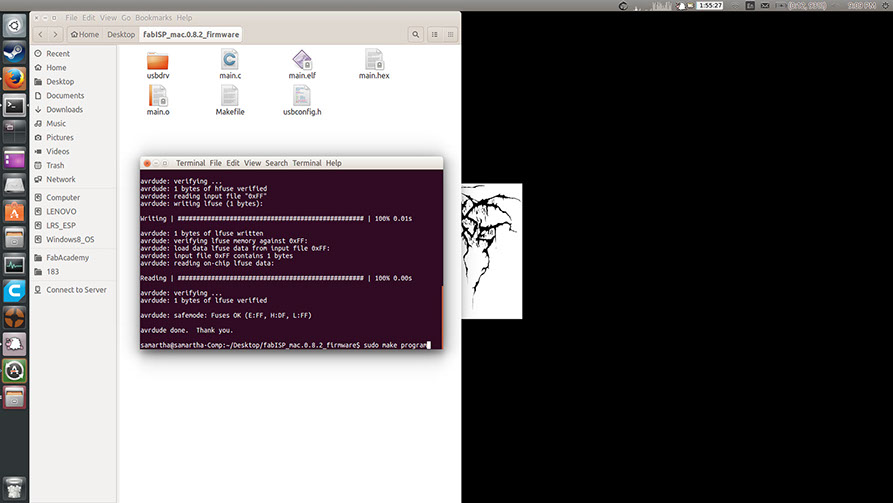
Step:05
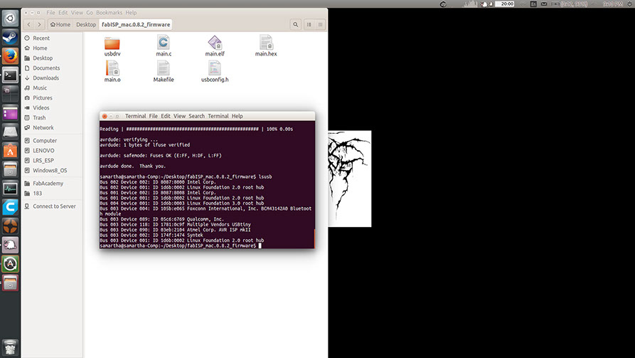
Type command "sudo make program"
It showed me the above message showing that the board was programmed successfully.
1-5
<
>
After successful programming of the Fab ISP, I connected it to my laptop using a USB cable to check whether it gets recognised as an ISP or not. And it did.
Below is a screenshot of my device manager, that shows my FabISP. This shows that my FabISP is functional.
.jpg?crc=3883160693)
.jpg?crc=4033558779)
Learnings from this week:
- Major learning this week was learning how to use Eagle. Since I am new to electronics, it was difficult to make the schematic in the beginning. But later as I worked for it, I found it easy.
- Another learning was to use the Roland MDX-20. I had never worked with this machine. So using it and understanding how to give commands to this machine was fun.
Step:01
Milling the FabISP
To start milling the FabISP , I first understood the method of working using Ubuntu (basics).So I documented each step of opening a file and creating .rml file for milling.
Step:02
Soldering the components
To start soldering the components,it is necessary to first make note of the components that are to be used.
Below is the list of components required for the FabISP board:
- ATTiny 44 microcontroller- Qty:01
- Capacitor 1uF - Qty:01
- Capacitor 10 pF - Qty:02
- Resistor 100 ohm - Qty:02
- Resistor 499 ohm - Qty:01
- Resistor 1K ohm - Qty:01
- Resistor 10K - Qty:01
- 6 pin male header - Qty:01
- USB connector - Qty:01
- 20MHz Cystal - Qty:01
- Zener Diode 3.3 V - Qty:02

EX-TERRA-DUR by Chandni Chhabra is licensed under a Creative Commons Attribution-ShareAlike 4.0 International License.