Week 5: 3D Scanning and Printing
Tasks for the week:
- Test the design rules for your printer(s) (group project)
- Design and 3D print an object (small, few cm) that could not be made subtractively
- 3D scan an object (and optionally print it)
Task:01
Testing the design rules for the 3D printer
We have an 'Ultimaker 2+' at FabLab CEPT.
Brief introduction to Ultimaker 2+:
"Engineered to perform, the Ultimaker 2+ is reliable, efficient, and user-friendly. Thanks to its support of a wide range of materials, it’s suitable for a huge variety of applications, from prototypes to customized tools. It’s a great all-around 3D printer that delivers consistent results."- LINK
Group Assignment:
Caliber testing:
Caliber testing for a 3D printer is a great way of finding out what 3D printing and slicing areas are problematic and which are easy. For, this I downloaded the files from Thingiverse here. I chose to print it in ABS plastic as it has more strength when compared to the PLA plastic. The parameters I set in Cura for this can be seen below:
%20(1).jpg?crc=220985650)
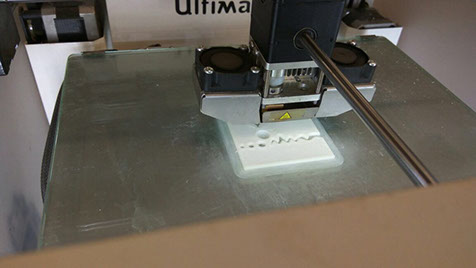
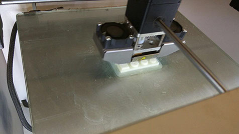
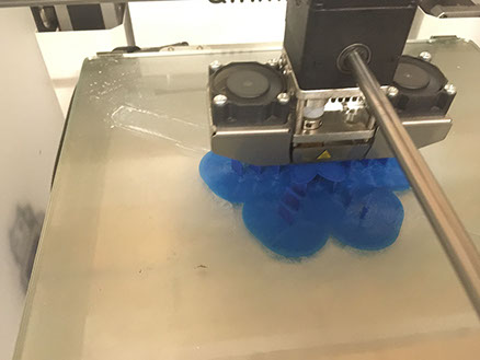
Image showing the printing process:
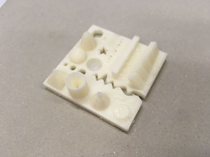
Image showing the final output:
Task :02
3D printing
The idea was to 3D print concentric spheres. So the first attempt was to find out the number of supports required for a single print.
So, I modelled spheres using Rhinoceros 5 that were cut at a flat base as my initial attempt.
The files can be accessed here.
This assignment helped me understand the capabilities of the 3D printer that helped me to design and plan supports for my design accordingly.
-crop-u20957.jpg?crc=19200122)
-crop-u21131.jpg?crc=182623585)
-crop-u21157.jpg?crc=4198249837)
-crop-u21183.jpg?crc=243108498)
-crop-u21209.jpg?crc=212367075)
-crop-u21261.jpg?crc=47123794)
-crop-u21365.jpg?crc=4278536558)
-crop-u21391.jpg?crc=3939856213)
My idea was to make a complex system using spheres that can only be fabricated using a 3D printer. So to begin with I made a 2D circle then used pipe command to add volume. Next, I rotated the ring and used polar array to have more of the same rings. The result is as seen above in image.
Next, I added supports below the sphere. I made planes weak so that I can snap them later.
Now, since I wanted various spheres inside one, I decided to follow the same technique of providing weak supports for the inner sphere.
Next, I used the same sphere, scaled it down and placed it inside the previous sphere. The image shows the result.
I followed the same procedure to add more spheres.
I made 3 concentric spheres that were composed of rings one inside the other as seen above.
At last, I added a solid sphere to complete it.
The above image shows, the final form that I prepared to 3D print. Next, I exported the object in '.stl' format.
<
>
.jpg?crc=4037330570)
I used 'Cura' to generate the gcode file for 3D printing. Cura has a simple and easy interface and it allows to do various settings to have as much accuracy possible.
As seen, I used the above parameters to generate the gcode. And it showed me a print time of about 6 hours.
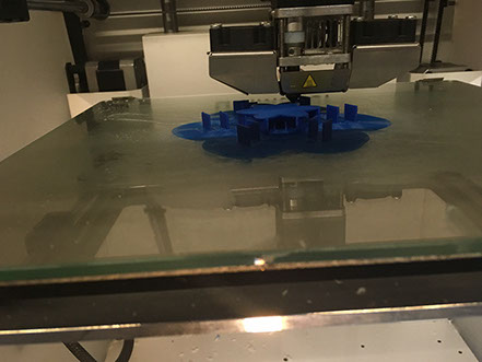
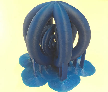
These images above show the object getting printed and the images on the left shows the final object. Now, it was time to snap the supports.
Below, is the video that shows the movement of spheres within the sphere after snapping all the supports. This could work as a toy for a kid or a dog. But the snapped edged need to be sanded with dremil. It was child safe after I smoothened the support edges with a dremil.
Task:02
Scan a 3D object and 3D print it.
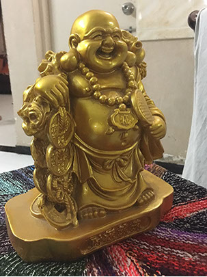
I chose to scan a 'Buddha' statue that I had at home for this assignment. I used a knitted coloured mat below the object as pattern usually helps to build edges correctly.
So to start with, I placed my object on a stool such that I can move around it and put a white sheet in the background to cut down the surrounding objects.
Also, I took pictures in a way that I cover the entire sphere around my object, so that I can capture each angle for detail.
I used my phone camera to scan it. I made a video of all the pictures it can be seen below.
Next Step:
Next, I needed to stitch images together to make a 3D object file. For this used Autodesk RECAP 360.
It has basic interface and very simple to use. All one needs is a set of pictures of the scanned object. Once uploaded, the 3D object gets stitched by the autodesk server. Below are the steps I followed for the same:
.jpg?crc=4018387480)
After logging in with the autodesk account, the above window appears. Here, I added the title for my project and also selected 'ultra' quality for the object mesh. Also, selected the 'obj' format as the final output for the file.
.jpg?crc=4196543106)
Next step, I uploaded the folder that had the pictures of my scanned object. The above window was the next step.
.jpg?crc=318561471)
Now, the next step was to relax, till the files got stitched. So, once the file is ready, it would show on the screen above.
.jpg?crc=4167709807)
The dashboard window showed me the progress of my file.
.jpg?crc=3985480587)
As seen in the above screen, I could see my file once it was ready.
.jpg?crc=3928341903)
I could rotate the the object, to view it from different angles to check the quality of the object. As seen, the object had the colours and shadows mapped by the pictures.
.jpg?crc=146599665)
I checked the quality of mesh by turning off the mapped textures. The quality looked good enough.
-crop-u45000.jpg?crc=4126352530)
Downloading the file:
I downloaded the file by clicking on 'Download' option from the '3 dots' seen on the right end of my file icon on the dashboard window.
847x477.jpg?crc=4158349269)
I could easily open the 'obj' file in Rhinoceros as a Mesh file. Above is an image for the same
Hero shot of the Object
Hero shot of the scanned 3D object
Files for this assignment can be acessed here.
Step:01
Milling the FabISP
To start milling the FabISP , I first understood the method of working using Ubuntu (basics).So I documented each step of opening a file and creating .rml file for milling.

EX-TERRA-DUR by Chandni Chhabra is licensed under a Creative Commons Attribution-ShareAlike 4.0 International License.