Embedded Networking and Communications
This week I will hook up some microcontroller to a I2C bus and let them communicate to each other. I will configure the flokit from output week to take the master role on the bus. Another flokit will be used to be the client and I will hookup one additional I2C device so I will end up with three devices communication with each other. See how to build the flokit in the link below.
The I2C protocol networking
I2C is a but protocol to enable up to 128 devices to communicate bi-directional. The ATmega328 chip is compatible with this protocol. It is describes in the documentation in chapter 22.2 in the datasheet.

This image shows the schematic of how to connect the devices on the bus. See how all two wires of the bus has a pull up resistor to the VCC line.
As the documentation of the microcontroller I also want to declare the basic terms of the I2C protocol
| Term | Description |
|---|---|
| Master | The device that initiates and terminates a transmission. The Master also generates the SCL clock. |
| Slave | The device addressed by a Master. |
| Transmitter | The device placing data on the bus |
| Receiver | The device reading data from the bus. |
Hookup the boards wiring one more time
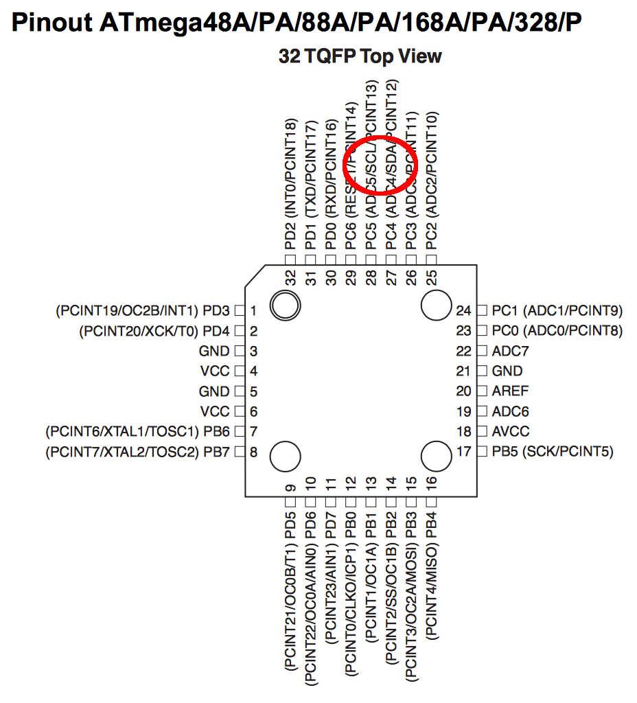
Finding the right pins on my microcontroller is easy then looking into the data sheet. They are mentioned as SDA and SCL on the pinout schematic.
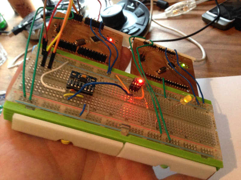
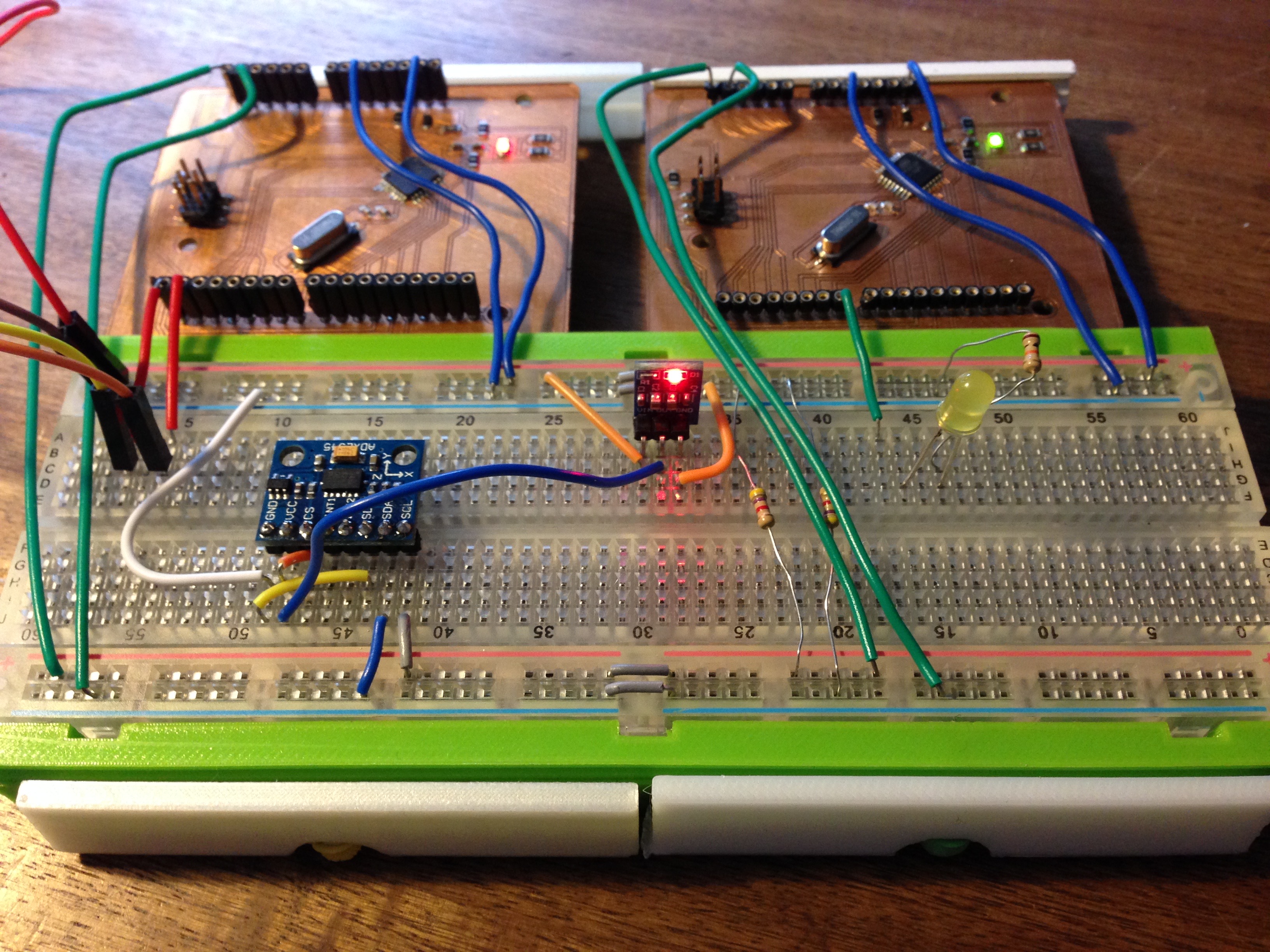
Here I show how I used my breadboard to hookup all the devices needed for this assignment. I used the top red and blue line normal as 5V power and ground pipe. The lover lines I used as the I2C bus. The red line is the SCL (clock) and the blue one is the SDA (data) line. Both of those lines are pulled up by two 4.7k resistors.
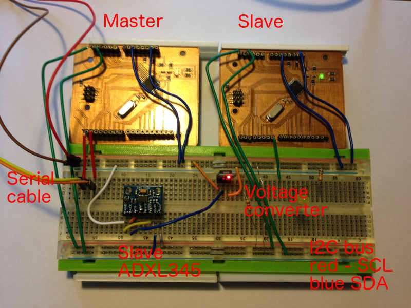
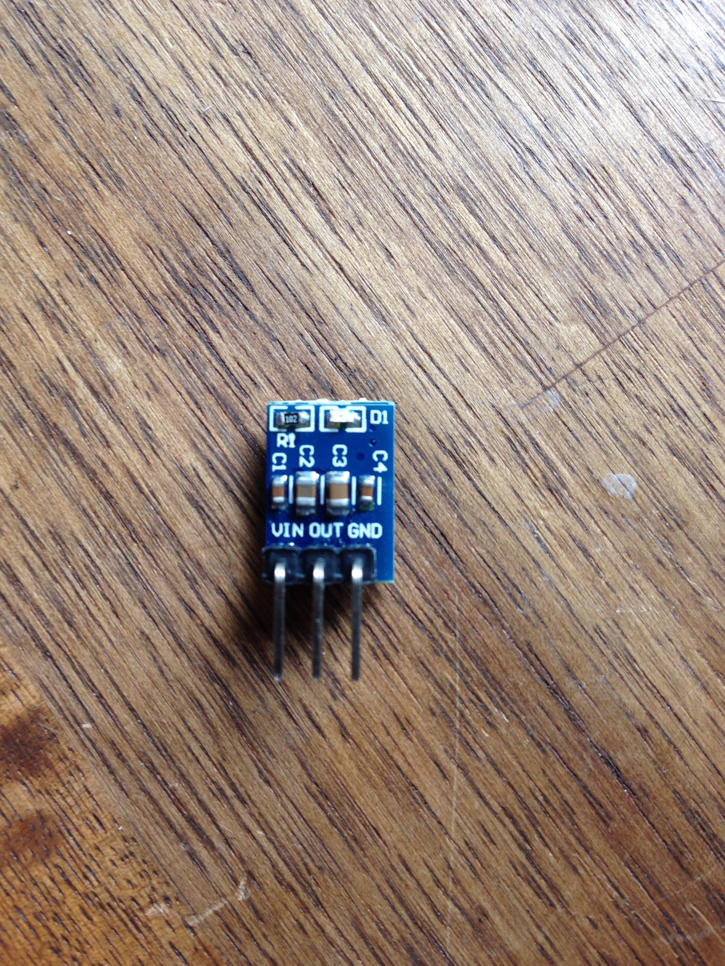
On the left I used my FTDI cable to communicate with the master board to read the debugging information. The center of the breadboard is all about the third device the ADXL345 chip that also communicate on the I2C bus and its power supply the chip that the power downscales to 3.3V.
ADXL345 library import libraries
I found this library that makes it easy to use the ADXL345 breakout board on the I2C bus. Please visit this link Adafruit_ADXL345 to get the latest version of it.

To use the library open sketch->library in your Arduino IDE. Then search for ADXL and download and install the Adafruit library. To use this library you will also need the Adafruit_Sensor.h library that you will find here
ADXL345 I2C slave get moving
The ADXL345 sensor is a three axis sensor that runs over SPI (another bus protocol) or I2C. Because we want to hook everything up to the same bus i choose I2C for this assignment.
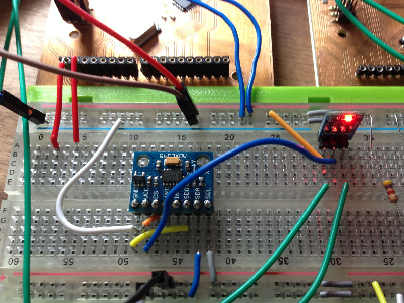
There are a lot of hardware that runs on 3.3V instead of 5V that is needed by the microcontroller. Thats why I hat to use a 5V to 3.3V converter to hook up the ADXL345 without damaging it.
Coding teach the chip I2C
To accomplish this assignment I will have to code two different sketches because the master and the slave will use different ones.
#include <Wire.h>
#include <Adafruit_Sensor.h>
#include <Adafruit_ADXL345_U.h>

/* Assign a unique ID to this sensor at the same time */
Adafruit_ADXL345_Unified accel = Adafruit_ADXL345_Unified(12345);

bool slaveLED = false;

void displaySensorDetails(void) {
  sensor_t sensor;
  accel.getSensor(&sensor);
  Serial.println("------------------------------------");
  Serial.print  ("Sensor:       "); Serial.println(sensor.name);
  Serial.print  ("Driver Ver:   "); Serial.println(sensor.version);
  Serial.print  ("Unique ID:    "); Serial.println(sensor.sensor_id);
  Serial.print  ("Max Value:    "); Serial.print(sensor.max_value); Serial.println(" m/s^2");
  Serial.print  ("Min Value:    "); Serial.print(sensor.min_value); Serial.println(" m/s^2");
  Serial.print  ("Resolution:   "); Serial.print(sensor.resolution); Serial.println(" m/s^2");
  Serial.println("------------------------------------");
  Serial.println("");
  delay(500);
}

void displayDataRate(void)
{
  Serial.print  ("Data Rate:    ");

  switch (accel.getDataRate())
  {
    case ADXL345_DATARATE_3200_HZ:
      Serial.print  ("3200 ");
      break;
    case ADXL345_DATARATE_1600_HZ:
      Serial.print  ("1600 ");
      break;
    case ADXL345_DATARATE_800_HZ:
      Serial.print  ("800 ");
      break;
    case ADXL345_DATARATE_400_HZ:
      Serial.print  ("400 ");
      break;
    case ADXL345_DATARATE_200_HZ:
      Serial.print  ("200 ");
      break;
    case ADXL345_DATARATE_100_HZ:
      Serial.print  ("100 ");
      break;
    case ADXL345_DATARATE_50_HZ:
      Serial.print  ("50 ");
      break;
    case ADXL345_DATARATE_25_HZ:
      Serial.print  ("25 ");
      break;
    case ADXL345_DATARATE_12_5_HZ:
      Serial.print  ("12.5 ");
      break;
    case ADXL345_DATARATE_6_25HZ:
      Serial.print  ("6.25 ");
      break;
    case ADXL345_DATARATE_3_13_HZ:
      Serial.print  ("3.13 ");
      break;
    case ADXL345_DATARATE_1_56_HZ:
      Serial.print  ("1.56 ");
      break;
    case ADXL345_DATARATE_0_78_HZ:
      Serial.print  ("0.78 ");
      break;
    case ADXL345_DATARATE_0_39_HZ:
      Serial.print  ("0.39 ");
      break;
    case ADXL345_DATARATE_0_20_HZ:
      Serial.print  ("0.20 ");
      break;
    case ADXL345_DATARATE_0_10_HZ:
      Serial.print  ("0.10 ");
      break;
    default:
      Serial.print  ("???? ");
      break;
  }
  Serial.println(" Hz");
}

void displayRange(void)
{
  Serial.print  ("Range:         +/- ");

  switch (accel.getRange())
  {
    case ADXL345_RANGE_16_G:
      Serial.print  ("16 ");
      break;
    case ADXL345_RANGE_8_G:
      Serial.print  ("8 ");
      break;
    case ADXL345_RANGE_4_G:
      Serial.print  ("4 ");
      break;
    case ADXL345_RANGE_2_G:
      Serial.print  ("2 ");
      break;
    default:
      Serial.print  ("?? ");
      break;
  }
  Serial.println(" g");
}

void setup(void) {
  Serial.begin(9600);  // Start serial
  Serial.println("Accelerometer Test"); Serial.println("");

  /* Initialise the sensor */
  if (!accel.begin()) {
    /* There was a problem detecting the ADXL345 ... check your connections */
    Serial.println("Ooops, no ADXL345 detected ... Check your wiring!");
    while (1);
  }

  /* Set the range to whatever is appropriate for your project */
  accel.setRange(ADXL345_RANGE_16_G);

  /* Display some basic information on this sensor */
  displaySensorDetails();

  /* Display additional settings (outside the scope of sensor_t) */
  displayDataRate();
  displayRange();
  Serial.println("");
}

void loop(void) {
  /* Get a new sensor event */
  sensors_event_t event;
  accel.getEvent(&event);

  if (event.acceleration.x > 0 && !slaveLED) {
    Serial.println("x is positive send on signal to slave board");
    slaveLED = true;
    Wire.beginTransmission(22); // transmit to device #22
    Wire.write(1);        // sends one bytes for blinking LED
    Wire.endTransmission();    // stop transmitting
  } else if (event.acceleration.x <= 0 && slaveLED) {
    Serial.println("x is negative send off signal to slave board");
    slaveLED = false;
    Wire.beginTransmission(22); // transmit to device #22
    Wire.write(0);        // sends one bytes for blinking LED
    Wire.endTransmission();    // stop transmitting
  }

  delay(500);
}
The master code first of all import the ADXL345 library from Adafruit. It also initialize the Wire library from Arduino that is implementing the I2C functionality. Then the board will communicate with the acceleration chip and print out all its setup parameter to the serial bus.
In its main loop will test the x axis of the ADXL board and when it has a positive value it will communicate with the other flokit and inform it about the change.
#include <Wire.h>

int LED = 7; // LED on pin 7
int I2C_ADDRESS = 8;  // Address for this slave

void setup() {
  Wire.begin(I2C_ADDRESS);                // join i2c bus with address #8
  Wire.onReceive(receiveEvent); // register event

  pinMode(LED, OUTPUT);
}

void loop() { // Nothing to to here
}

// callback for revieving I2C events
void receiveEvent(int howMany) {
  int x = Wire.read(); // receive byte as an integer
  if (x == 0) // read the message check if this is 0
    digitalWrite(LED, HIGH);
  else
    digitalWrite(LED, LOW);
}
The flokit slave code is much more simple and straight forward. It listen on the I2C bis and when it it informed about the change from the master controller it switch a LED on or switch it off.
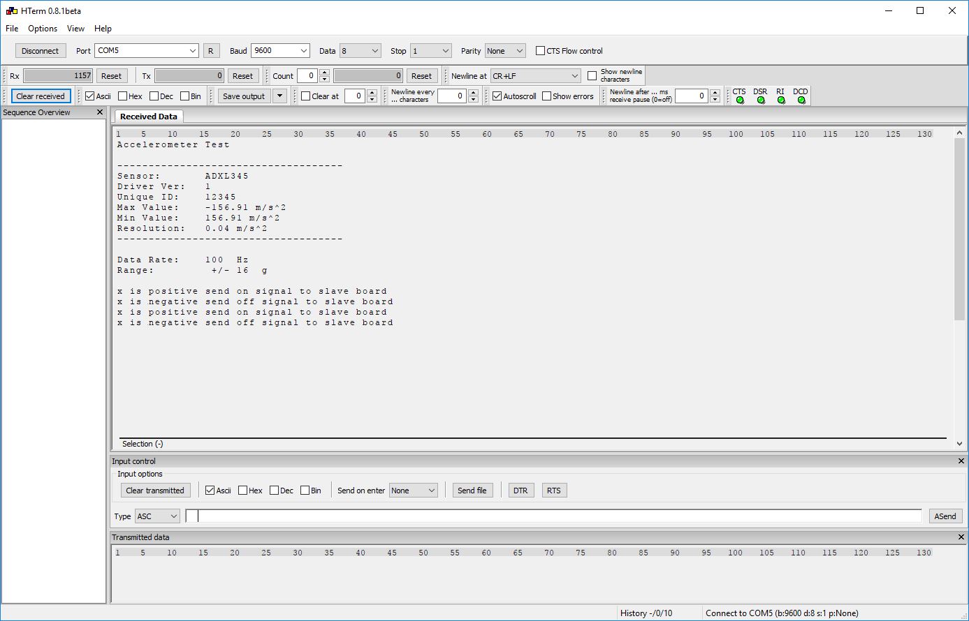
I2C master serial debugging
The master device also has a serial connection for debugging use. It tells all details about the ADXL345 chip.
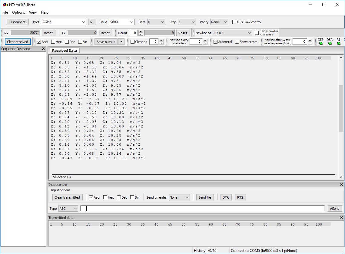
Later I changes the code to its final state where only the init values are posted on the serial and it informs about the positive to negative position change of the ADXL chip.
Testing led on position change
The images below shows how the led lid up then hold the breadboard with the ADXL in the right position. When lay the breadboard down on the table the led switch off.
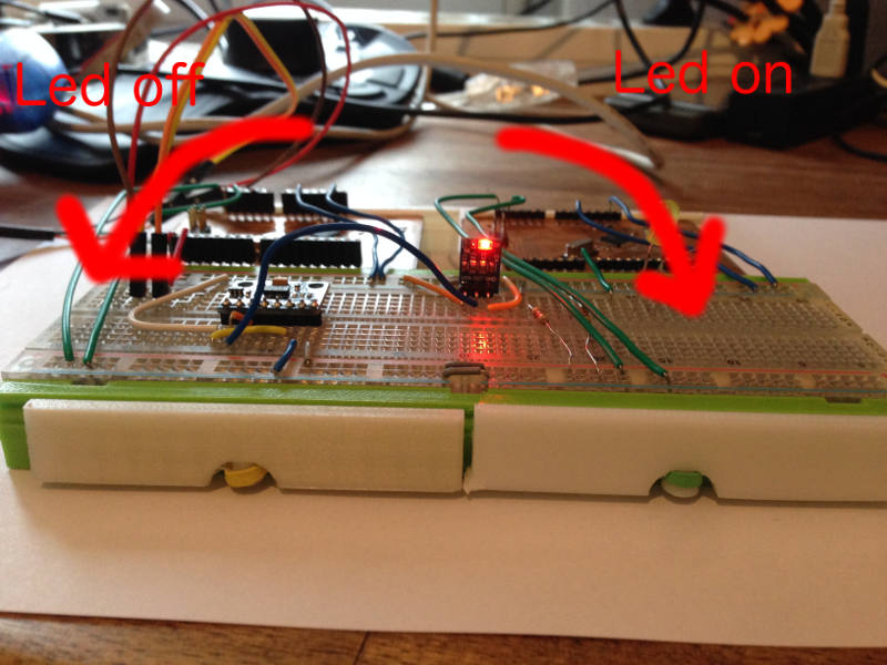
The image describe how the circuit work. When tilting the board right the led switch on. When tilting left the led switch off.
Download section try yourself
| Master code | download |
| Slave code | download |