Output Devices try to communicate
In this week I will be using a LCD display that is driven by my own custom Arduino clone board.
This week is the first part of a two week process. I want to combine the input and output week together to make a nicer project. If you're interested in whats going on after this week please feel free to read on in week 13 assignment to see the finished project.
Creating my own breakout board design thinking
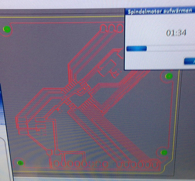
For the input and output week I want do design my own board similar to the Arduino footprint. This is because I want to be able to use Arduino Uno shields later. For this task I used the eagle files that comes from the Arduino homepage and alter them in eagle. I throw away all the inner circuits and build it ab again with my own parts but the pin header for the shield stay the same.
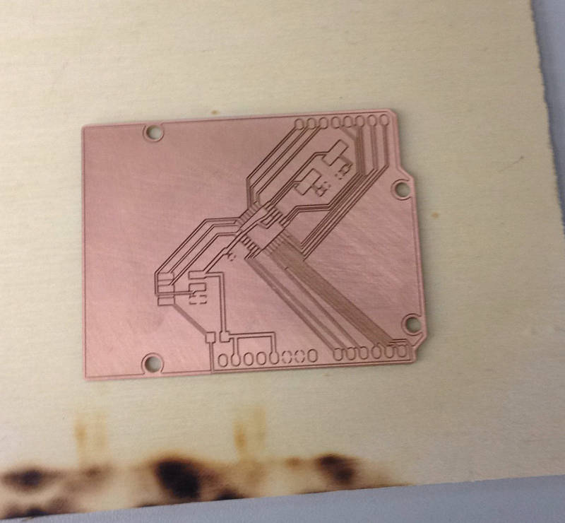
As learned before I placed all the parts the the board and bake it. The result was satisfying.
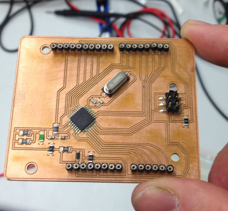
When the board was finished I tested the position of the pin sockets to see if my idea works and I can add normal Arduino add-on shield onto my own board.
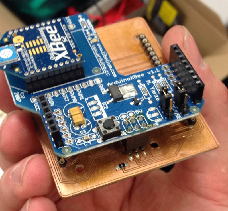
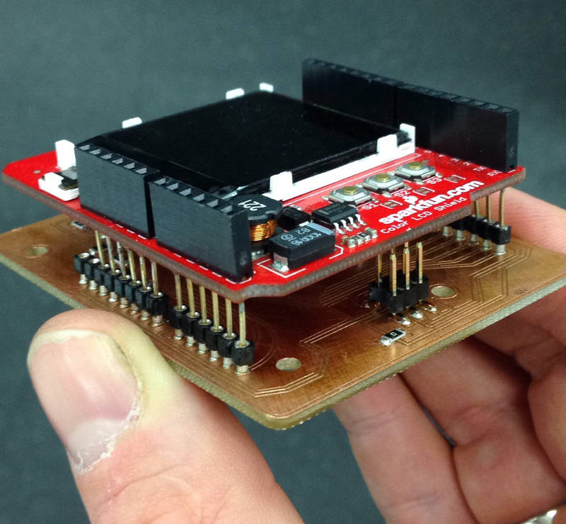
As you can see the the add-on shield fit onto the board. Because the pin sockets are not perfect for the job it is a little bit tricky to attach the shields to it but it works.
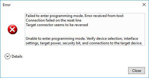
First there was I problem on my first attempt to program the board. The problem was, that I connected the ISP header with a pul up resistor to vcc to pull the reset pin up. I figured out that I has to cut the trace to exclusively connect the ISP header reset pin the to 328's reset pin. After that everything works as expected.
It's time to export the files from EAGLE to get the design into the Mill software.
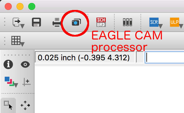
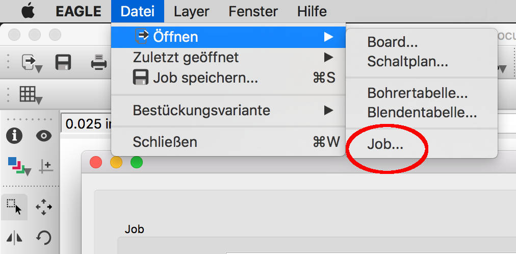
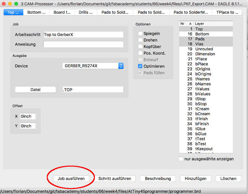
Here you can download the LPKF cam configuration also the ready to import files for the LPKF software. To do so you click in EAGLE in the CAM processor image in the top toolbar. The images above show the steps to take to export machine files from EAGLE. You have to load a Job. This is some kind of confusing but this means in general to load a configuration how to export files. In a .cam file are all the configurations what is the electronic mill capable off. You can get the .cam file for our LPKF machine in the download section below.
Download section stuff to download
| Original dump from the ATmega328 chip | download |
| FloKit (Shield compatible) | download |
| LPKF cam export job for EAGLE export | download |
| ready to mill files (zip) | download |
Bill of materials parts to rebuild the board by yourself
| Qty | Value | Device | Package | Parts | Description | |
| 1 | DIODE-DO214AC | DO214AC | D1 | DIODE | ||
| 1 | LEDCHIPLED_1206 | CHIPLED_1206 | LED_GREEN_ON | LED | ||
| 1 | PINHD-2X3SMT | 2X03_SMT | ICSP | PIN HEADER | ||
| 1 | SJW | SJW | SJ1 | SMD solder JUMPER | ||
| 4 | 0k | R-EU_M1206 | M1206 | R4, R5, R6, R7 | RESISTOR, European symbol | |
| 2 | 100n | C-EUC0603K | C0603K | C5, C6 | CAPACITOR, European symbol | |
| 1 | 10k | R-EU_M1206 | M1206 | R2 | RESISTOR, European symbol | |
| 1 | 10x1F-H8.5 | PINHD-1X10_ARD | 1X10 | IOH | PIN HEADER | |
| 2 | 1k | R-EU_M1206 | M1206 | R1, R3 | RESISTOR, European symbol | |
| 2 | 22p | C-EUC0603K | C0603K | C2, C3 | CAPACITOR, European symbol | |
| 1 | 6x1F-H8.5 | PINHD-1X6 | 1X06 | AD | PIN HEADER | |
| 2 | 8x1F-H8.5 | PINHD-1X8 | 1X08 | IOL, POWER | PIN HEADER | |
| 1 | ATMEGA328P-AU | ATMEGA328P-AU | QFP80P900X900X120-32N | ATMEGA328P | ||
| 1 | CRYSTALS-NOGND-4-HSMX | CRYSTALS-NOGND-4-HSMX | HC49-4-HSMX | X1 | CRYSTALS CAN NOT GROUNDED |
Arduino testing start easy
To test the 1602A display I want to use I begin with hookup it to an Arduino uno board so see if the display is working correctly.

I used the LiquidCrystal.h library from Arduino's internal libraries. It was very well documented. Follow the link to the Arduino Library sample Arduino LCD display
/*
 * LCD_Arduino_FabAcademy
 *
 * Created: 02.05.2017 12:23:30
 * Author : Florian Paproth
 */

// include the library code:
#include <LiquidCrystal.h>

// initialize the library with the numbers of the interface pins
LiquidCrystal lcd(12, 11, 5, 4, 3, 2);

void setup() {
  // init the with numbers of rows and cols
  lcd.begin(16, 2);
  // Add text to LCD
  lcd.print("FabAcademy");
}

void loop() {
  // set the cursor to column 0, line 1
  // (note: line 1 is the second row, since counting begins with 0):
  lcd.setCursor(0, 1);
  // print the number of seconds since reset:
  lcd.print(millis() / 1000);
}
FloKit version start easy
In my own board I will not use the Arduino library to drive the display. I will use plain c with the avr library and also an additional library the LCD Library for driving my display. Sure I could write it directly in c with the help of the datasheet but this would be too much work for this week and it is more likely to use libraries for such tasks that are well tested and better coded as I could do this.

This is the FloKit with the LCD display hooked up similar to the Arduino version. I only used some other digital output pins to match the library configuration but this could be easy changed if necessary.
With the library in place I wrote some code to fulfill the equal job as the Arduino did.
/*
* LCD_FabAcademy.c
*
* Created: 02.05.2017 23:26:54
* Author : Florian Paproth
*/
#define F_CPU 16000000 // Important to set the correct CPU freq for the display and for delay
#define LED_ON PORTD |= (1 << PD7) // turn LED on code
#define LED_OFF PORTD &= ~(1<< PD7) // turn LED off code
#include <stdio.h>
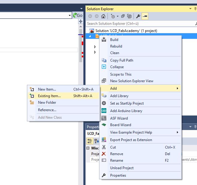
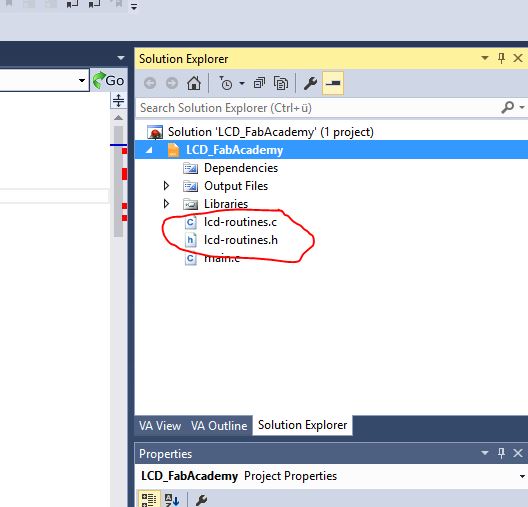
#include "lcd-routines.h" // Import the LCD library
#include <avr/io.h>
#include <util/delay.h>
void setTime(int uptime){
lcd_clear();
lcd_home();
// Set the FabAcademy text
lcd_string("FloKit uptime");
lcd_setcursor( 0, 2 );
char Buffer[20]; // in diesem {} lokal
itoa( uptime, Buffer, 10 );
lcd_string( strcat(Buffer , " sec") );
}
int main(void)
{
// Initialize the LCD
lcd_init();
int uptime = 0;
while(1)
{
_delay_ms(500);
LED_OFF;
_delay_ms(500);
LED_ON;
uptime++;
setTime(uptime);
}
return 0;
}
This is a video of working display.
Download section stuff to download
| Display control (Arduino IDE) | download |
| Display control FloKit (Atmel Studio) | download |