_Week04_ELECTRONICS PRODUCTION
_Introduction
For electronics production week it was the first time face to face to for me to create an electronic circuit from scratch, solder it and make it work properly. We work through how to create the gcode, manage the milling machine, solder and programm the board (getting scare of everything).
_Background
Electronics production nowdays work like a worldwide developing bussines that have specialized people who manage from the design of the electronics (function, dimensions, components), manufacture, test and sell these small parts of the machines and some system that use this functional parts.
Machines used in this assignment availables in the FabLab BCN
_Week Assignments
_Workflow /Step by Step
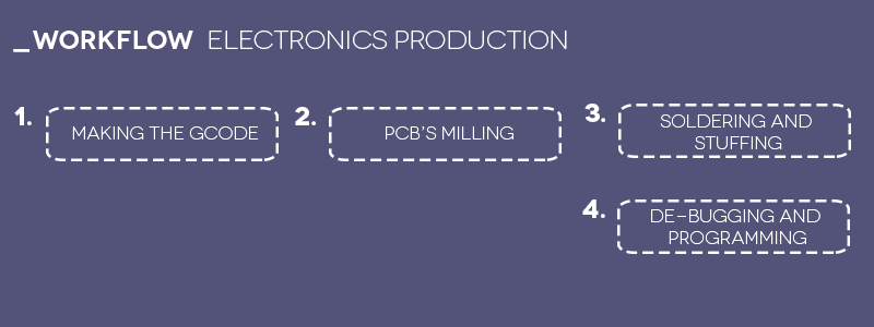
_Making an in-circuit programmer by milling the PCB.
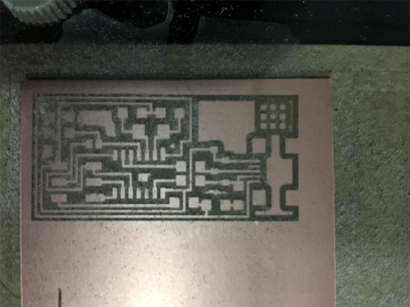
_Making the gcode and milling the PCB board.
For the first try I used the Modela MDX-20 that worked fast and with very good quality it's kind of all machine but still working well.
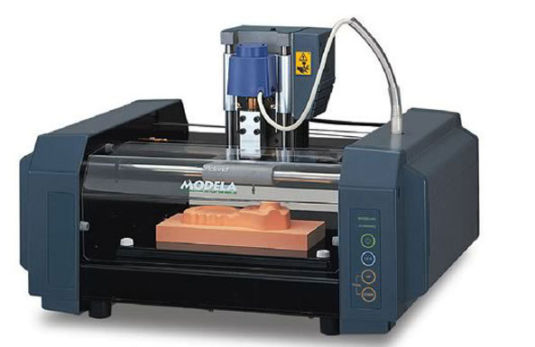
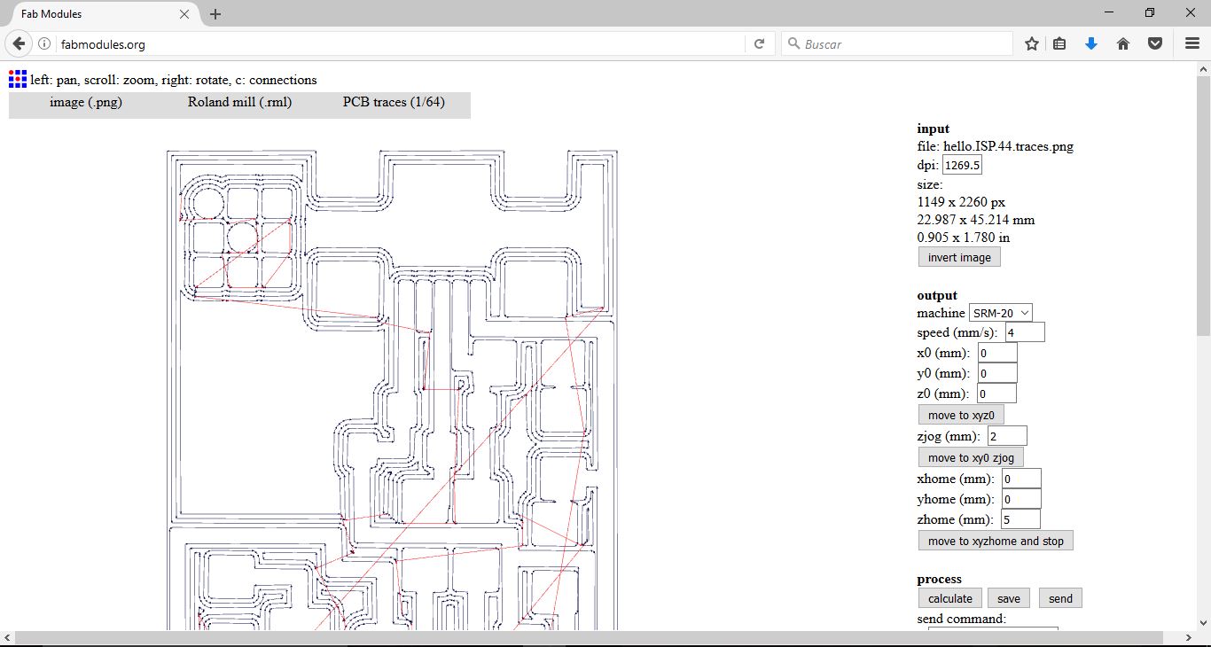
To start with the process, I converted the PNG files of the traces and the interior that Neil provide to us in the FabModules in order to have the gcodes for making the milling process.
- Speed 96 mm/min.
- Spindle 9290rpm aprox.
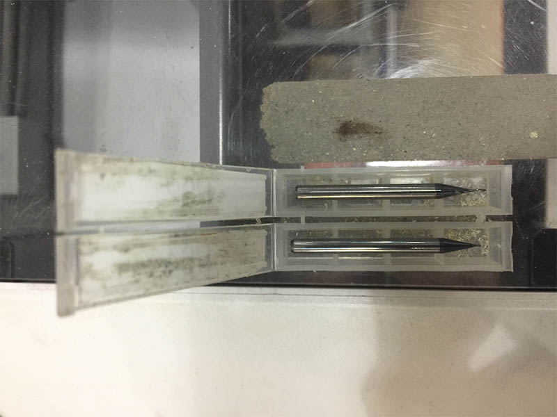
- 1/64 drill for traces.
- 1/32 drill for interior board.
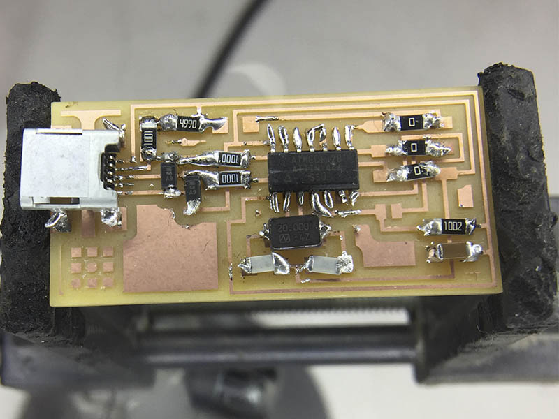
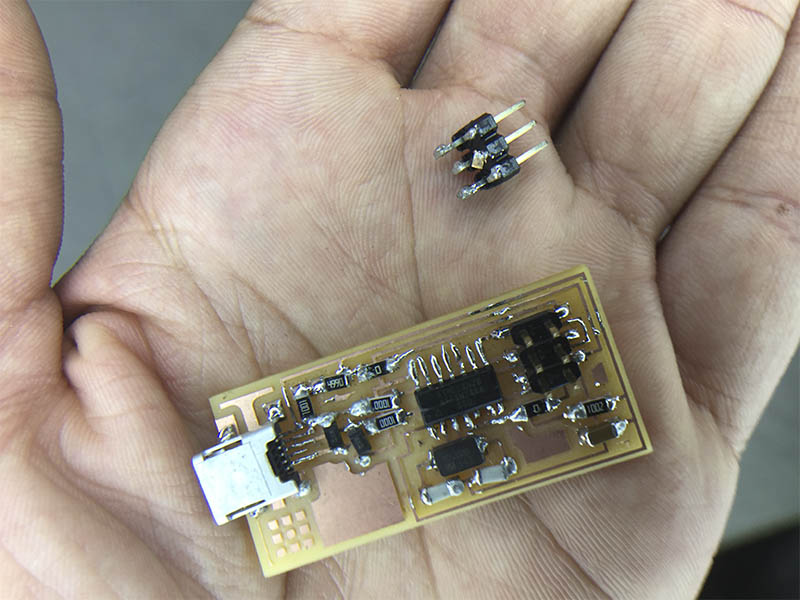
_Soldering and putting all together.
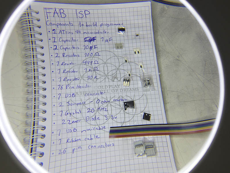
This part were a hole tortute for me because I´m so hasty always also I have a very shaky left-hand and my eyeglasses are already dont help me a lot but then I gain very good advices from all my tutors like find a support point for my arms, use a magnifying glass and work in a very good iluminated workspace. First, I done a list with all the components that i will need for soldering the card remembering each name and code and following all the instructions in the docs starting with the MiniUSB and the microcontroller, and then with the resistors and capacitors.
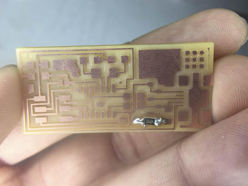
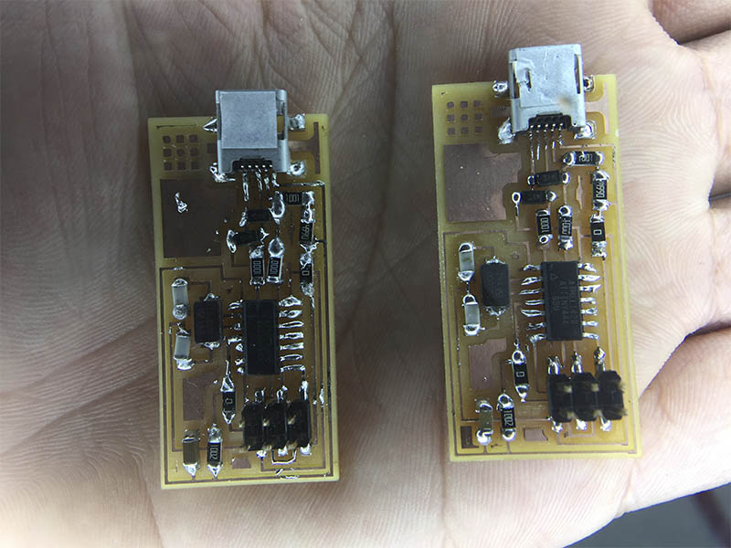
I messed up very good my card putting a lot of tin in the components so all combine and doesnt work very well after finishing soldering and also I confused the jumper with the 0ohms resistors so when I releved this ones I removed the cupper band so I have to put more copper with a copper sticker and then the current flow good. As well, when we try for the first time the card and doesnt worked, for disconnect the USB cable aslo removed the MiniUSB connector so I have to putted then again two times (as you see in the images).
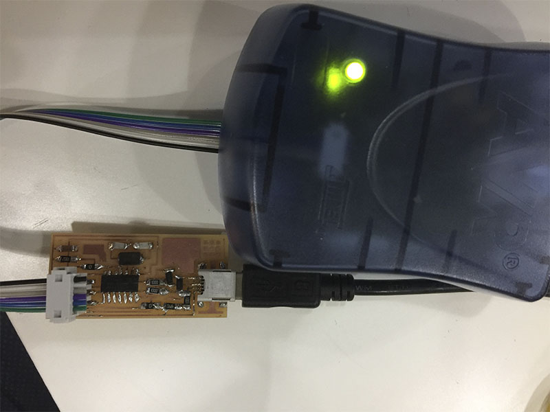
_De-bugging and programming the board.
At the end of several repairs, finally the green light turn on showing that all the connections were correct.
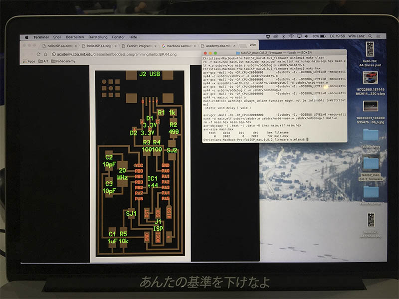
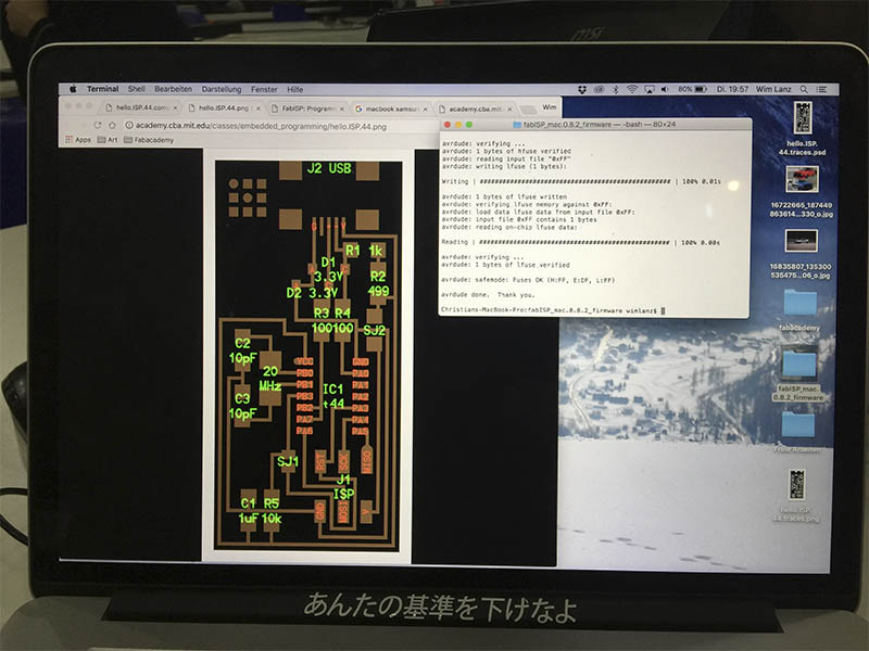
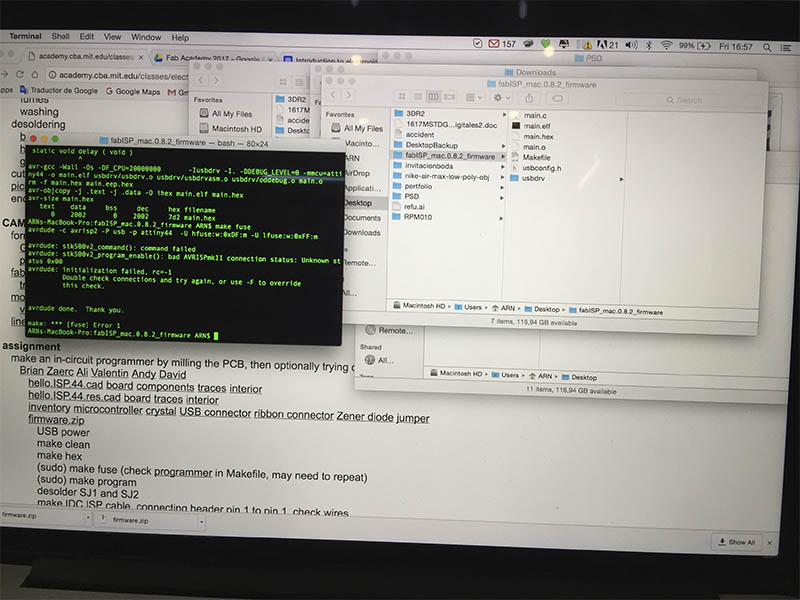
So in order to programming the card I could not use my laptop because of in the tutorial apper an error of using Windows to programm so my dear friend Wim Lanz supported me with his computer so I could try to program my card as it follows:

I put all the commands as you see in the images, the de-bugging were correct but at the end I could not program the card because appeared an error, Arnau told me that was because most of all the components have a lot of tin in the connections so that makes interference in the energy flows.
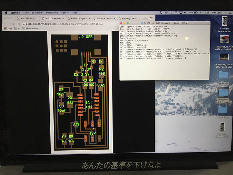
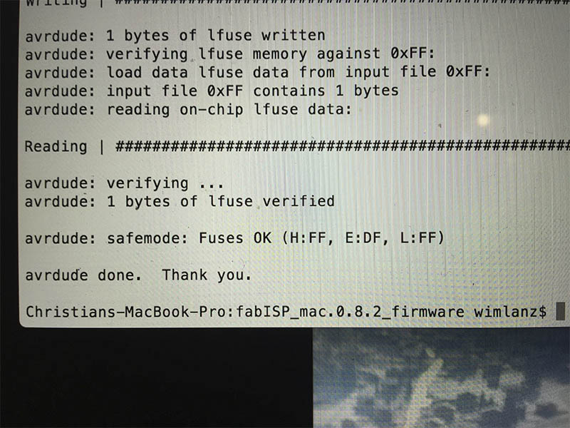
Next thing I have to do in order to could program the card it´s to clean and the excess of tin in all the components.
So at the end there was so many fixes in the board so I decided to do a next try.
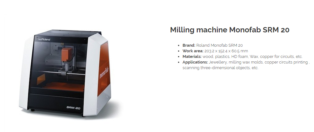
_Making the gcode and Milling the PCB board.
This time I used the Milling machine Monofab SRM 20 (but the Modela had better quality) following these steps:
For milling the PCB traces:
- Put double side tape to the back of the PCB for not moving of the plataform.
- Adjust the drill 1/64.
- Set from the software manually X/Y and Z.
- Let the drill drop softly in the new X Y Z.
- Set the new X Y Z in the buttons on the right side.
- Upload the gcodes (previously done in FabModules) in the CUT button, then DELETE ALL-ADD GCODE-OUTPUT.
- Set Speed at 60%.
- Press VIEW button for see if the work were correct.
- Press Z button to change the drill to 1/32 NOTE: X and Y stays do not reset it.
- Set new Z home manually.
- Press CUT and upload new gcode and press output.
- 1. Always have a little bit of thin on the peak of the soldering iron.
- 2. First put the soldering iron for 5 sec in the surface where is gonna be the component.
- 3. Put the component and then put the soldering tin with one hand and in the other the tin over the component.
- Adjust the drill 1/64.
For milling the PCB outline:
_Soldering and putting all together.
For the second chance I follow this tips for soldering the board:
NOTE:The tin have to be smooth and shiny over the solded parts.
_De-bugging and programming the board.
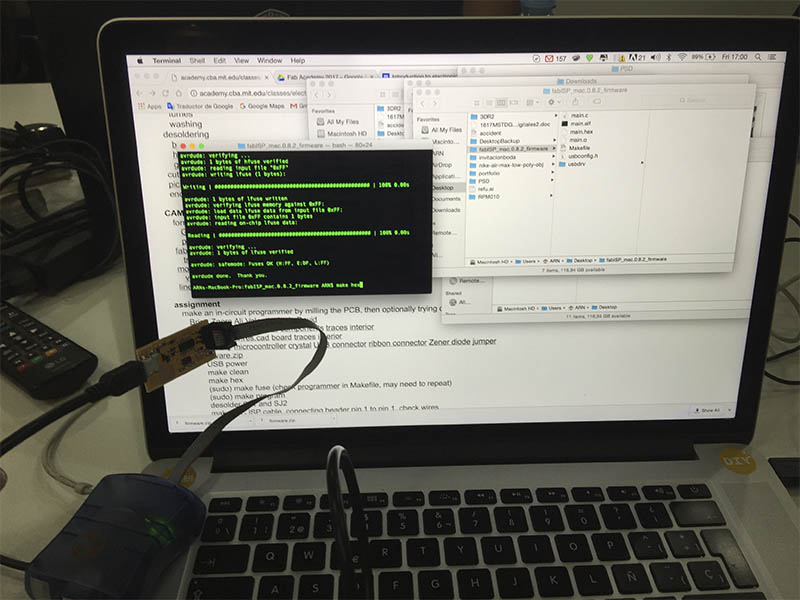
This time Arnau helped me to let cleaner the board and program with his computer, first appear an error so we checked again all the connections for programming.
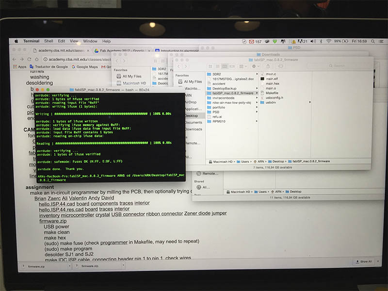
Finally we can programm the board in his computer and all worked perfect.
_Final review.
Weeks later I managed to solve the error and start programming on my computer (and also after get full infected of virus in week07).
_FILES
All the files for this assignment are available to download here