The objectives of this assignment is to make something big.
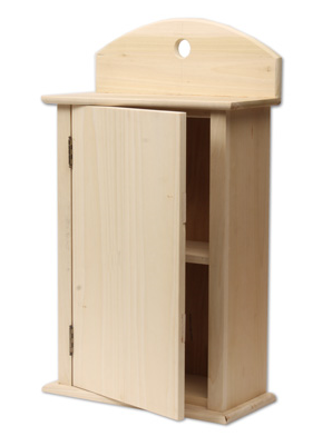
For this week I wanted to learn the basics of parametric design for this I have chosen to design a basic (press fit) cabinet.
I have never done any furniture (model) design in my life. Designing furniture and (that too) using parameters was a very ambitious project given the time constraints. For the 3D design assignment I had used Autodesk Fusion 360. Although I am not fully comfortable with it but I spent considerable time designing my project in it.
I started by making some sketches on the paper trying to setup dimensions and layout.
Design with Fusion 360
Fusion 360 and SolidWorks are very similar in that they both create models from outlines called sketches.From the rough sketch I made earlier I identified some key paramters which I declared in the design file
I then used these paramters in sketches to size up the dimensions as per requirement.
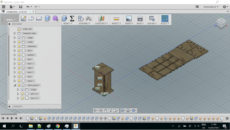
To cut the design on CNC machine we have to lay all the pieces of the design on a horizontal plane. To perform this task in Fusion 360, I found this video very useful.
Like wise I was able to layout pieces on a plane.
The design file is available here .
Preparation of CNC Machine Code
Once the design is ready. We need some sort of post processing to generate codes which CNC machines can understand.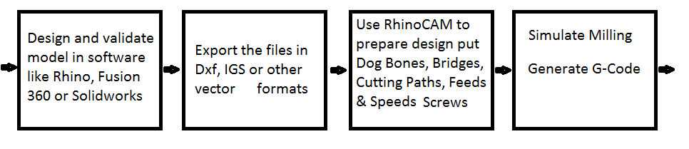
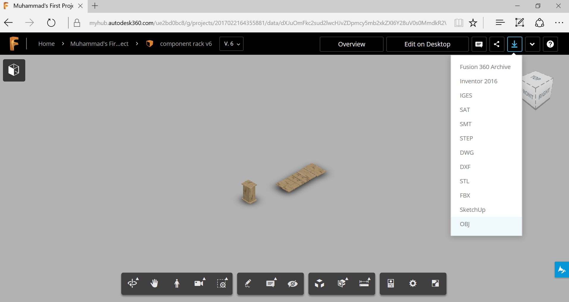
After 3 days of toil and (alot of) fustration with fusion 360, I was able to export the project in obj and .igs format using the web portal of Autodesk fusion 360. This is the basic format which is used for post processing and machining.
The preparation of machine executable code is performed through Rhinocerous CAM software. Although there are several CAMing softwares available but Rhinocerous CAM is an industry standard and consistent with all CNC machines.
Before anything we have to choose the machine for which we want to g-code. This is done through machine icon in top menu
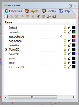
The first step is to layout design on the stock and place different components in appropriate layers. A typical design would include layers like screws, dogbones, engraving, pocketing inner and outer cuts.

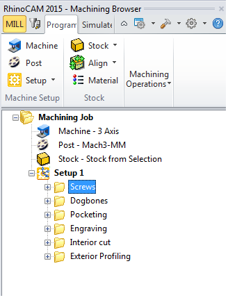
The preparation of G-Code for CNC machine is performed using Rhinocerous. RhinoCAM is an addon tool which allows user to write CNC milling instructions which can be converted to G-code.
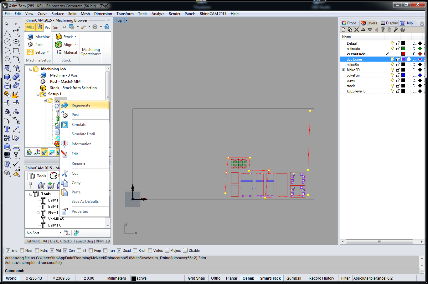
RhinoCam works by creating set of jobs maching jobs in the right hand segment of the window. The first job is to place screw dots which holds the stock. The dots placed in screw layer are selected The objects are seleceted and placed in a job by selecting the appropriate layer.
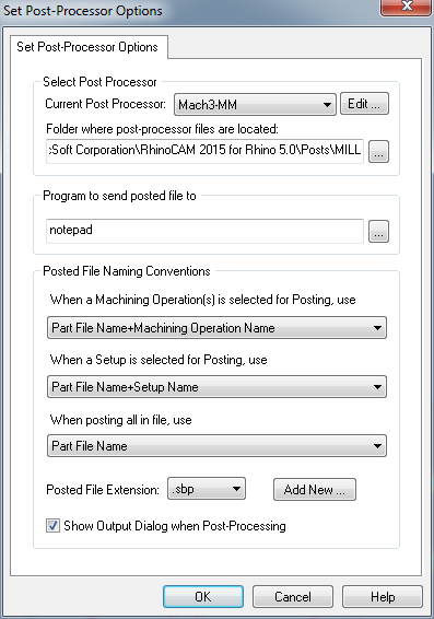
The tool path is created by regenerate and g-code is obtained through post
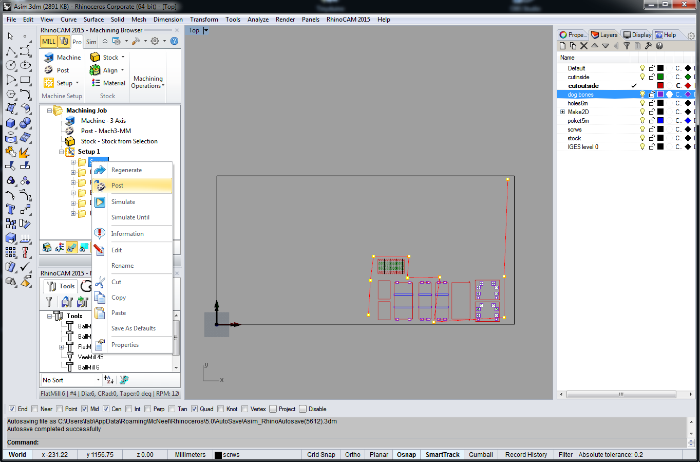
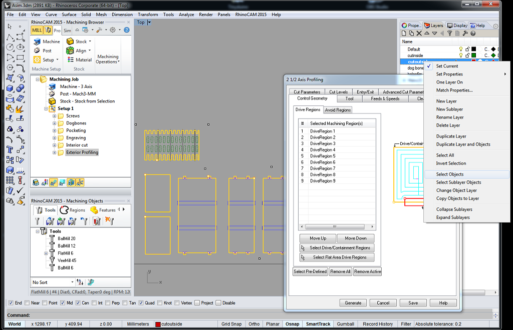
Other jobs such as dog bones, engraving, inner and outer cuts are created from the correspnding layers similarly.
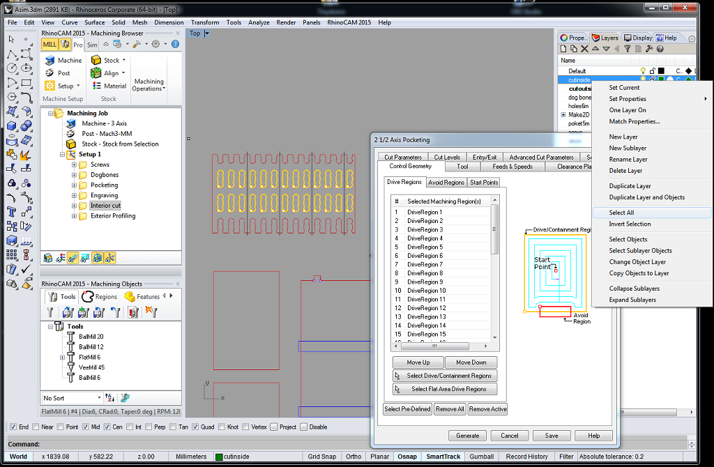
Here I would like to discuss some important parameters which should be considered when designing the strategies and toolpaths. These paramters are available in configuration manuals
Some important (tabs) paramters are discussed here:
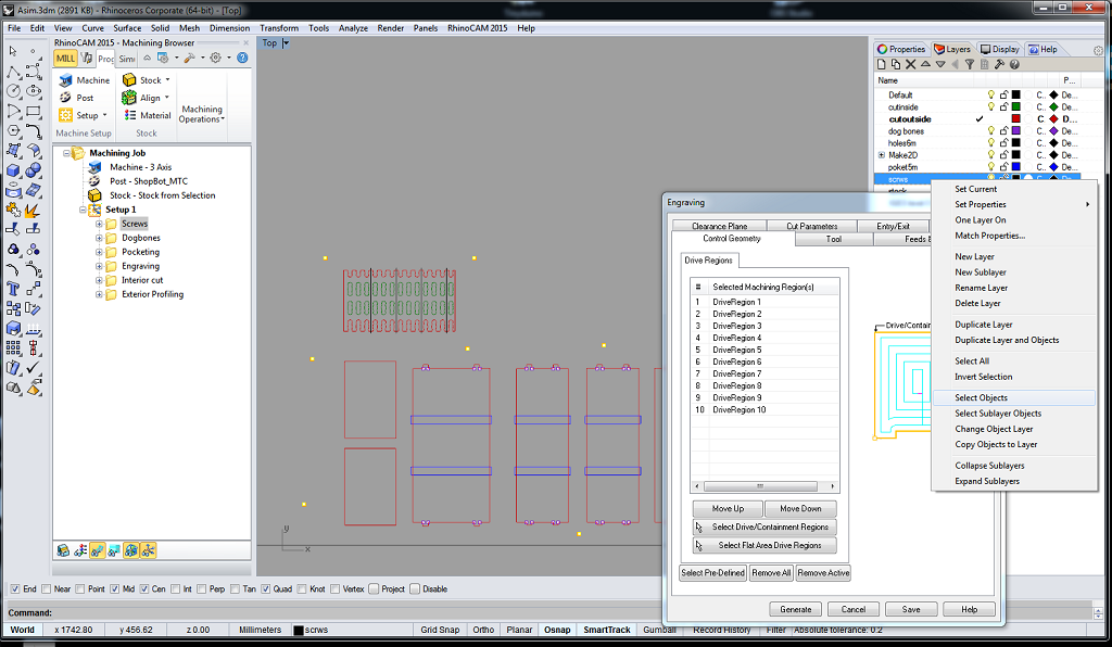
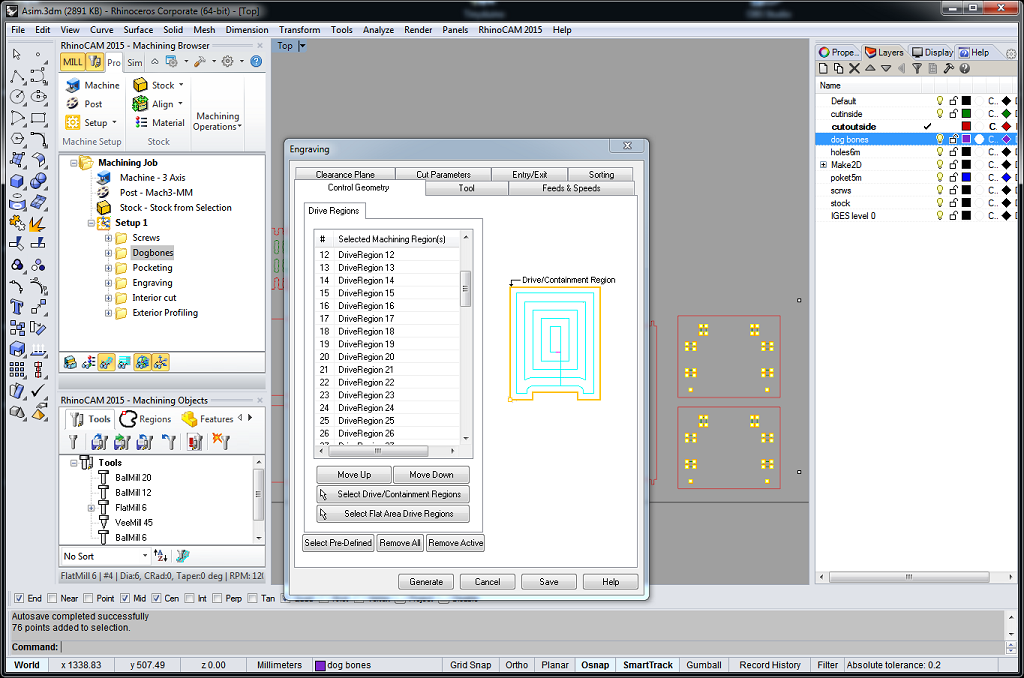
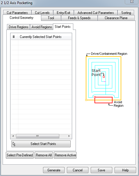
- Geometery Control tab defines line segments placed in the job and the regions machine needs avoid.
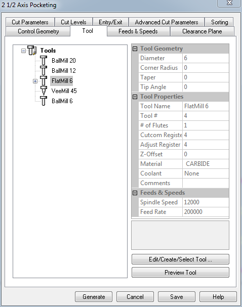
- Tools tab defines the tool being used for the job.
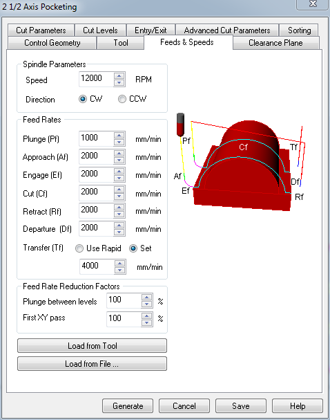
- Feeds and Speeds specifies the parameters including feeds and speeds, spindle speed and direction. These paramters must be adjusted for stock in use. The parameters I selected above are for standard OSB. However parameters specific to material can found online. I think that for high quality results the feeds and speeds, plunge tools ins and outs must be deliberated.
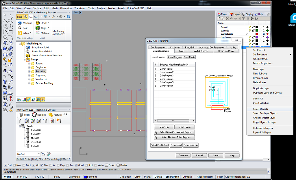
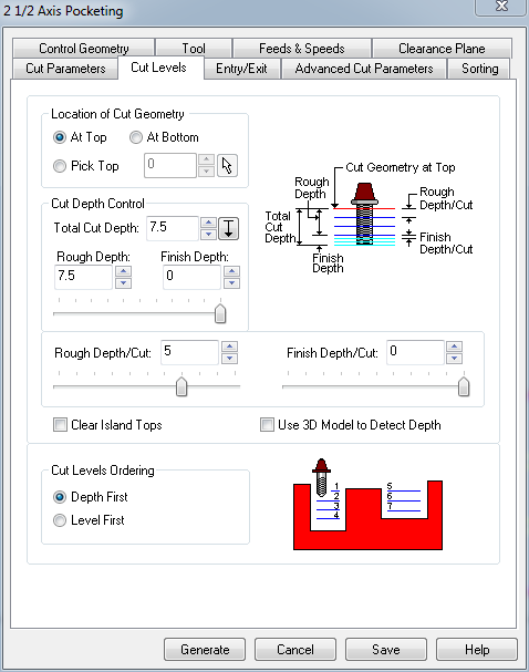
- Cut Levels specifies cut depths for pocketing and engraving the material.
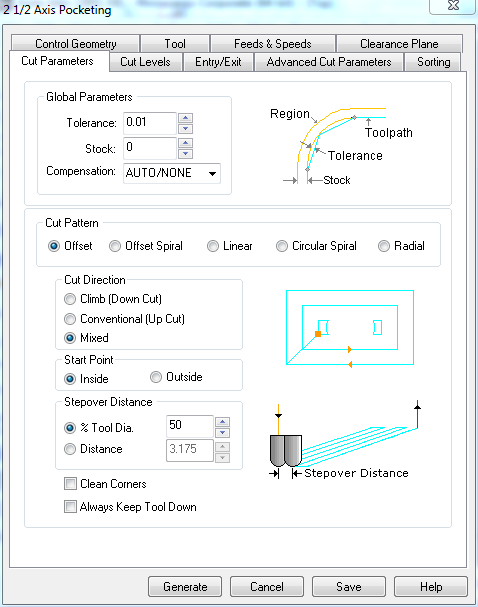
- Cut Parameter specfies features like cut direction, pattern and offset.
For exmaple the positions of screws holding the stock are saved in layer "Screws". The details of dog bones (required to make rectangular cuts) are placed in "Dog Bones" layer. The details of sections requiring engraving is stored in the "engraving" layer. The cuts (which can be from inside or outside of a perimeter ) are stored in "exterior_cut" and "interior_cut" layers respectively.
The screen-grab of RhinoCAM operations is embedded here for reference. The video walks through different stages of preparation of milling job.
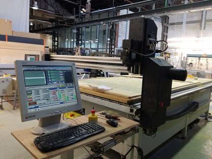
We have two CNC machines in our Fablab a shopbot and Precix milling machine. I will be milling my project on the Precix machine.

| Parameter | values |
|---|---|
Milling with the Machine
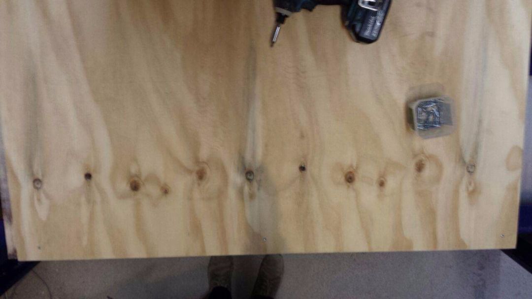
I followed these steps as I worked with the Precix machine:- Find and set (x0,y0,z0) on the machine.
- Fix the screws on the stock to ensure that the material is perfectly smooth. Because if the stock is uneven (even by a few millimeters) the milling may be errenous.
- After screw job is completed, I loaded the rest of the g-codes to the machine and it milled away marrily.
- Finished layout after cutting.
The Results of Milling
I brought in both the designs (patterned/kerffed table and small rack) into a single job. Since Santi was not sure if the process (with kerffed table) will go well so I decided to plug in just a fraction of the pattern to test the outcomes. The milling process lasted less than an hour and it was evident from the onset that the quality of finish depends on the quality material and the size of the drill bits.
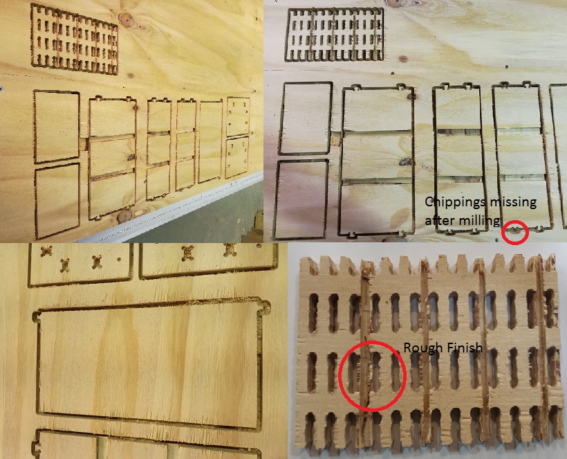
I realized that the dimensions of joineries were too small to hold together as milling machine made its way around them. The drilling the pattern did not bring any impressive finish mainly due to large drill bit size. I also realized that kerffing the surface to bend arround requires more attention to details e.g. the depth of profiling cuts and their repitition. I will be making some more attempts with revised parameters in the future.
The results of milling were not really as expected, there was alot to take away from this exercise. I realized that to deal small shapes (about 7 mm accross) I should have used tools of the size much smaller than 6 mm. Also the path going in and out from the material are important as material looses chippings.
The Finished Product
With the help of sand paper I trimmed away the rough cuts and removed chippings.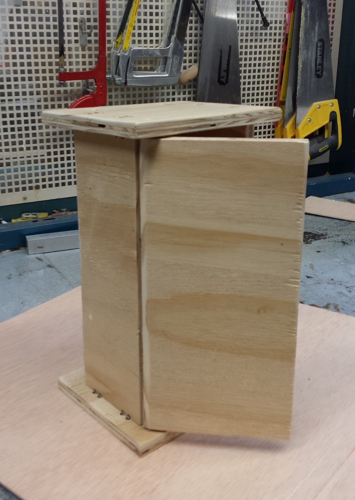
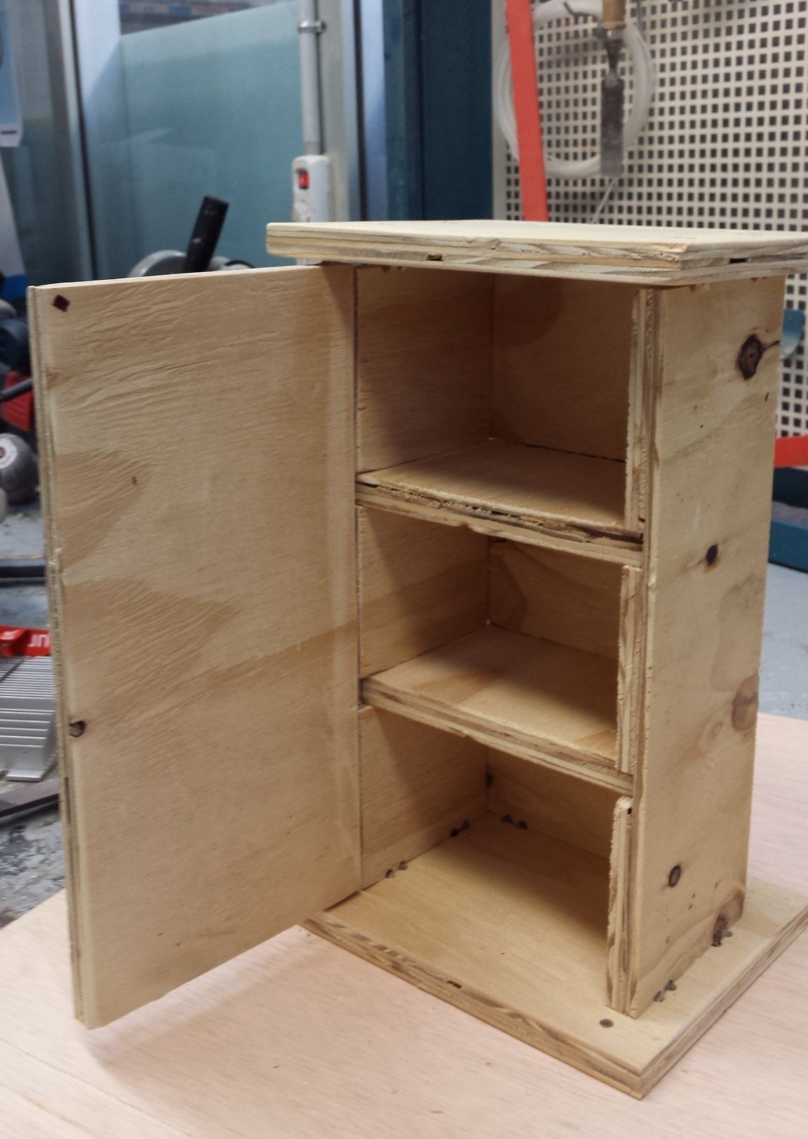
Albeit the design is not big in size but the going through the process has brought me working know-how of design and manufacturing process.
Learning Outcomes
From this extensive exercise I have come to conclude the following points.- Design of furniture using CNC tools requires proper understanding of software tools. The choice of right tool at the start of the process can simplify the process significatly.
- A careful look at the design and simple test (prototyping) using laser cut can enhance the chances of successful design at first milling iteration.
- The post processing of design model using RhinoCAM tool requires deliberate attention to detials. The toolpath, feeds and speeds must be optimized to suit the stock.
- Suitable number of bridges must be placed to ensure that milled pieces don't fall-off as a result of outer cut.
Downloads
Autodesk Fusion 360 files here.find all source files here.

This work is licensed under a Creative Commons Attribution-ShareAlike 4.0 International License
Copyright © 2017 Muhammad Asim Ali
This work is licensed under a Creative Commons Attribution-ShareAlike 4.0 International License
Copyright © 2017 Muhammad Asim Ali