This week is all about fabrication our own in system programmer i.e. FAB ISP.
The objectives of this assignment are:
- make an in-circuit programmer by milling the PCB, then optionally trying other processes.
Milling a PCB using Fab Modules
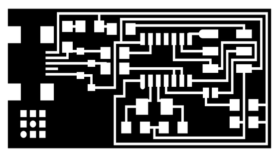
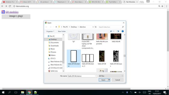
Although there are several ways to design and fabricate a printed circuit board (PCB). This week I have learned to fabricate a single layer PCB using PCB layout in graphical (.png) format and Fabmodules functionality.
The fab modules provide a set of software tools for personal fabrication, intended for use with machines commonly used in fab labs. It includes:
- Tools to design 2D and 3D objects.
- Functions to generate 2D and 3D toolpaths.
- GUIs workflow from design files to machine commands.
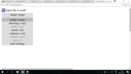
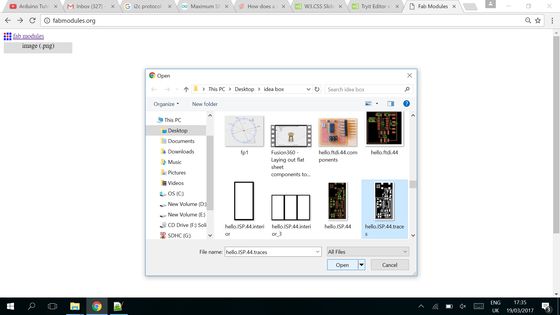
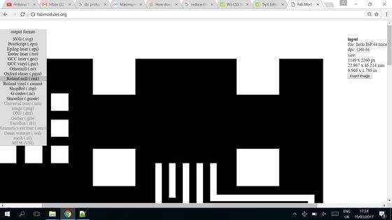
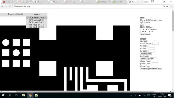
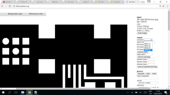
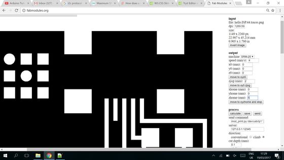
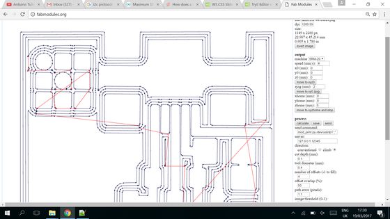
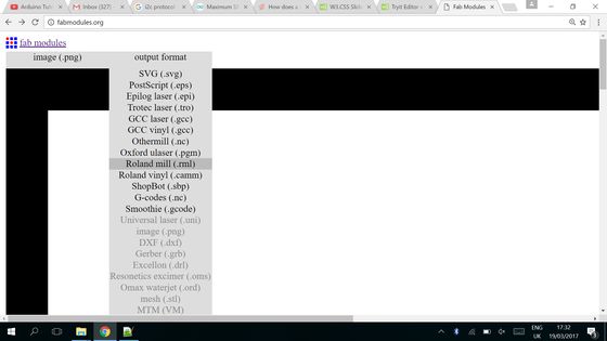
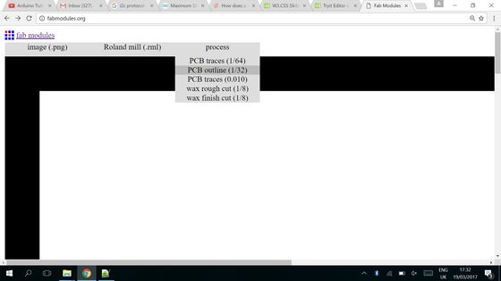
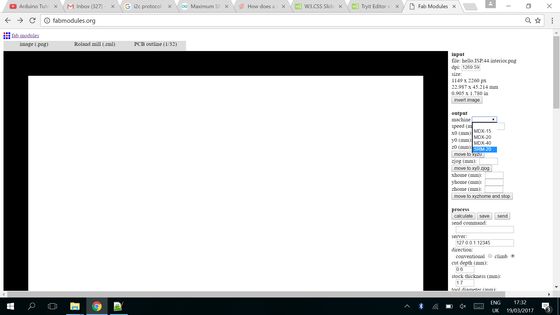
For the first part of this assignment I used Fabmodules to create the required (tool path) code for the milling machines. 1/64 and 1/32 size drill bits are selected for milling the traces and cutting the PCB respectively. The step by step procedure is illustrated in the following slide show.
A quick take video illustating the process of code generation for Roland milling machine is as follows:
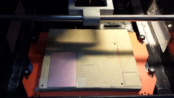
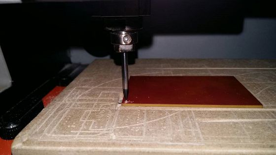
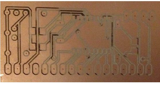
Once the codes were ready it was time to mill the PCB lamenates using drill bits. The most critical part of the milling the PCB is to ensure that base plate is perfectly smooth. Snice the milling machine removes the copper traces (which is 1.4 mil or 35 um for 35/35 laminate) a bend of even a millimeter could leave the milling process kaput:
Afew important things which I learned from my experiences
- To compensate effects of uneven bed surface, it's better to set z-axis zero just under the surface.
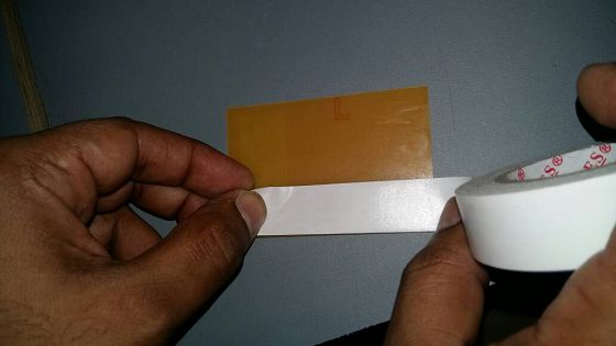
- To ensure that the laminate doesn't move during the milling process put alot of double tape.
- To avoid breaking drill bits they should be fixed sufficiently deep inside the collet.
- Start milling at low speeds and gradually speed up when you are sure all is okay.
- Several drill bits later I have learned that drill should be perfectly secured and free of any viberation.
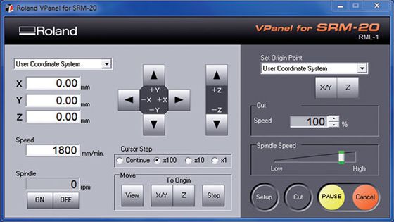
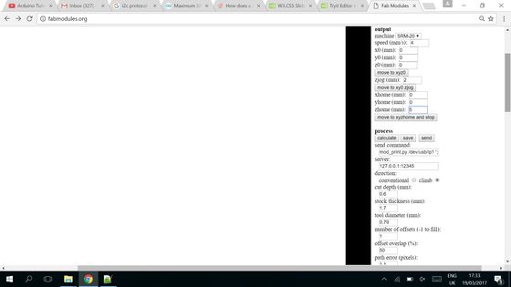
Roland SRM 20 software interface
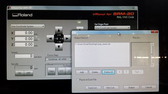
Load .RML file created through Fabmodules
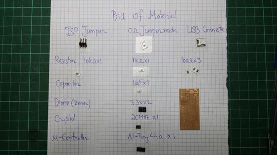
The bill of material
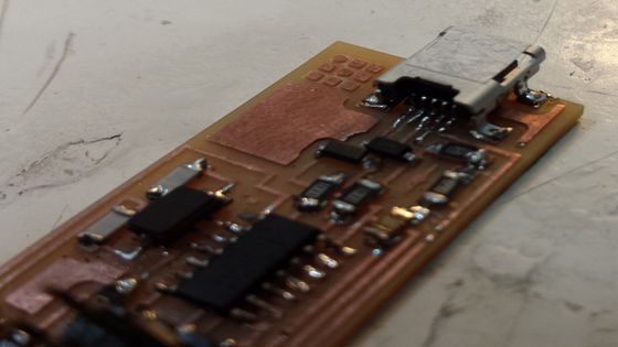
Soldered ISP
Example of incorrect milling
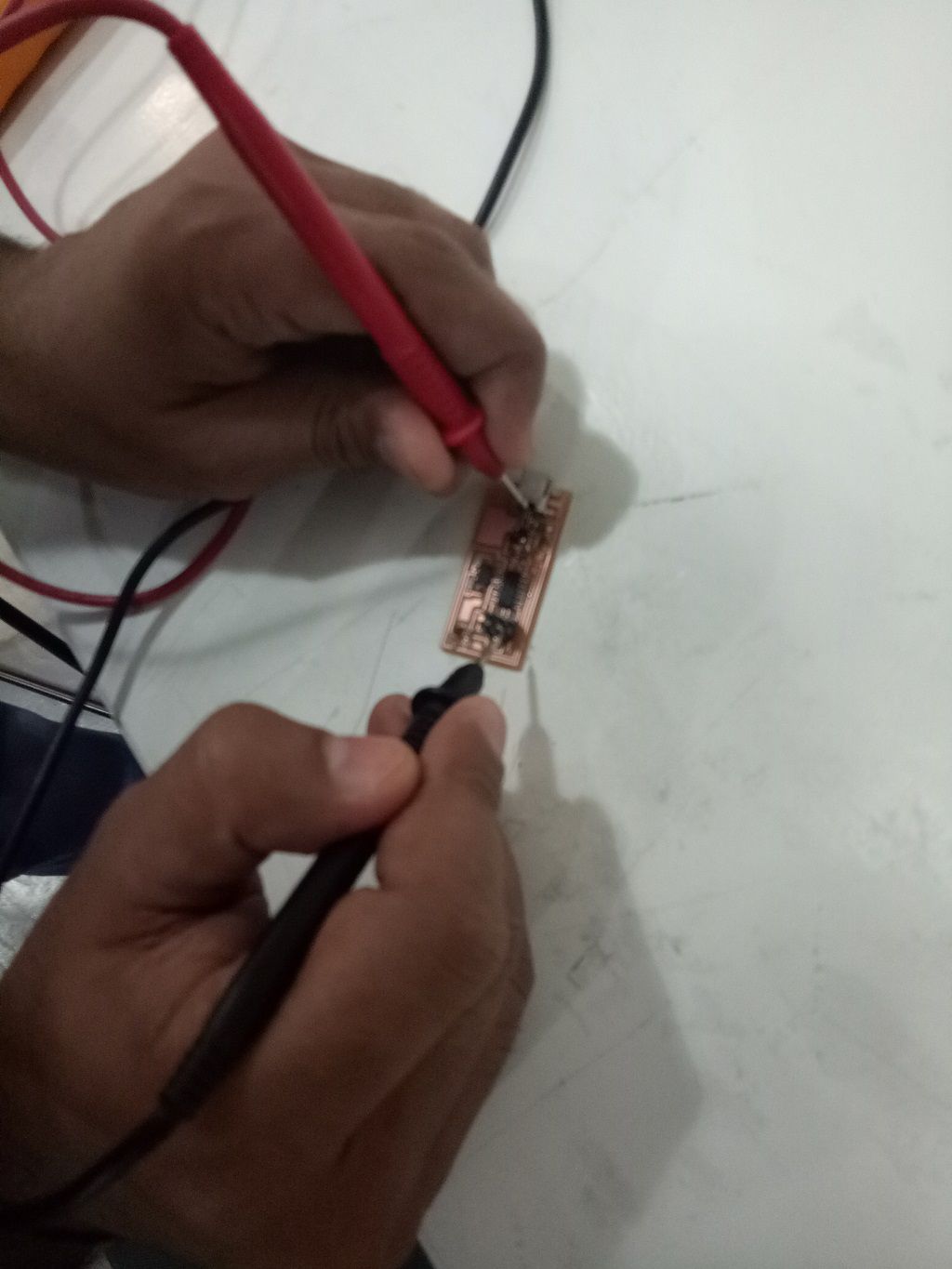
There were a couple of soldering problems which only the keen eyes of my instructor (Santi) could identify. A couple of contacts were not soldered properly. After systematic probe through the PCB using a DMM, the design was recognized by the computer.
Some Observations
After having worked with Roland modela SRM-20 and fabmodules I have come to realize the fact that the milling bed may not be always 100% flat and mill may not be exactly on the surface the best way to ensure proper milling is to turn on the spindle motor and carefully lower the z axis till it starts scratching the lamenate and then set the z to zero.Another important point I have come to learn through extensive usage of fabmodules is the trick to declare tool diameter manually. By decreasing the tool diameter from 0.4 mm to 0.38 mm or even .35mm and by reducing tool offset it is possible to mill boards which wouldn't be possible otherwise.
Another important point which I have come to learn from the experience of other colleagues is about double sided milling. Ideally speaking double sided milling with SRM-20 is very risky business however by drilling reference holes on one side of the PCB its possible to use them as reference points on the other side.
Soldering iron should not be always turned to the highest level, a very hot solder iron typically causes pads to come off the PCB.
After soldering it was time to program the Fab ISP through AVR ISP programmer. I connected the Fab ISP and AVR ISP programmer to the my laptop and the lights of AVR ISP indicate the state of micro-controller. At the first attempt the lights was red which typically happens due to loose soldering contacts. After manually checking all the traces with the help of DMM, I ironed out all issues.
From my experience the most tricky part to solder is the USB header which has particularly thin traces and is very hard to solder.
System can be checked by simply connecting it to AVR ISP and connecting the FAB ISP through USB.
Programming of Fab ISP
After a few rounds of troubleshooting all the contacts were ok, it was time to program the device using AVR ISP programmer.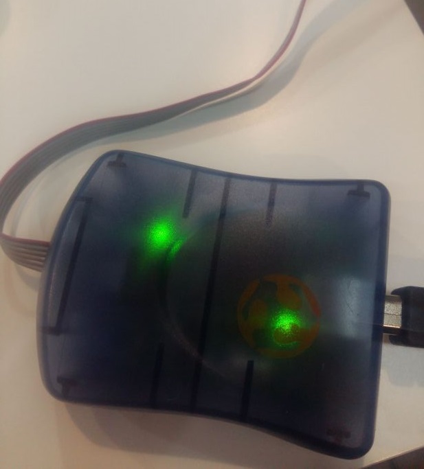
If AVR ISP recognizes the FAB ISP the LED truns green.
The standard procedure to program the Fab ISP is provided at Fab Academy website. I downloaded the files and installed the driver and winavrdude is already installed on my computer. But despite several attempts I couldn't not program the Fab ISP module in windows 10.
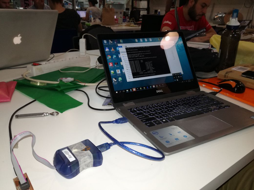
FAB ISP and AVR programmer are both connected to USB ports of the Laptop
After several attempts we tried the same operation on Santi's Mac and it was a success. Why burning of bootloader didn't go through on windows computer is still a problem I would like to look into.
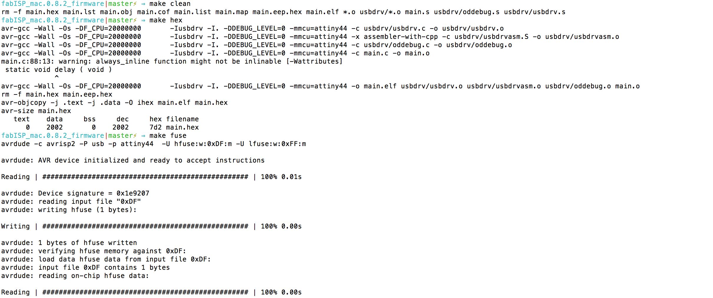
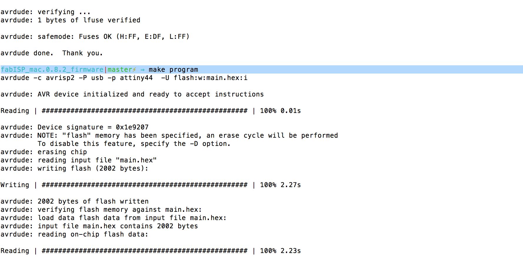
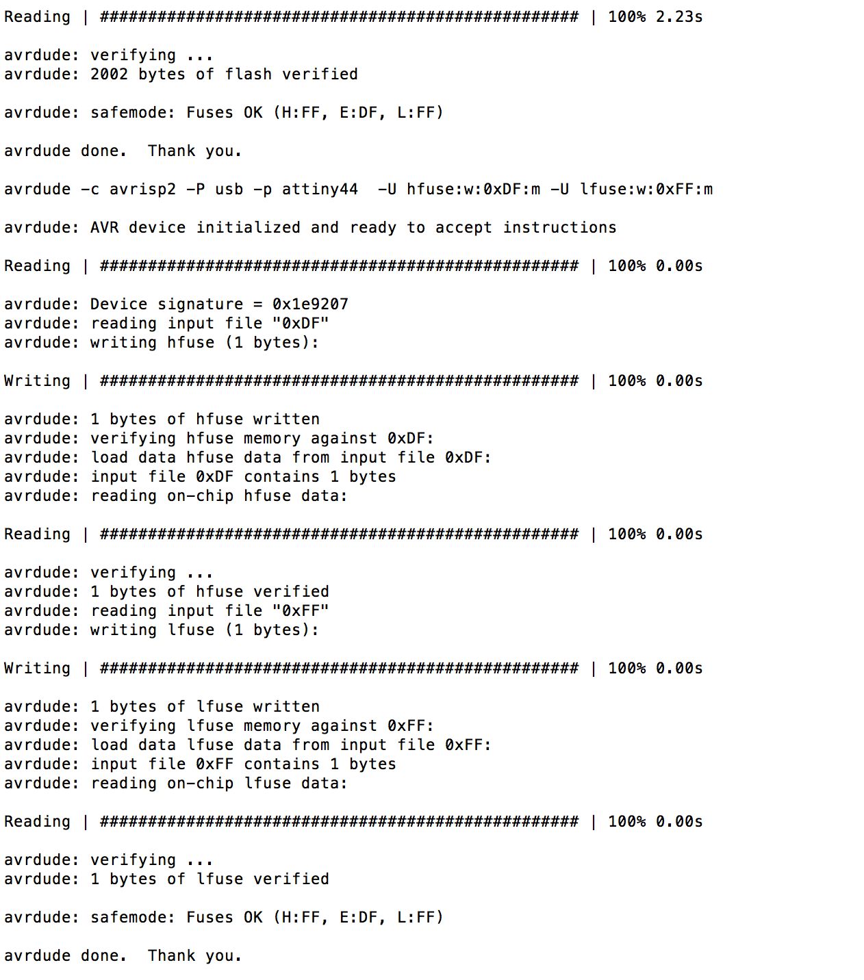
The output of the programming process is reproduced here
Once the programming was successful, I desoldered the 0 ohm resistors.
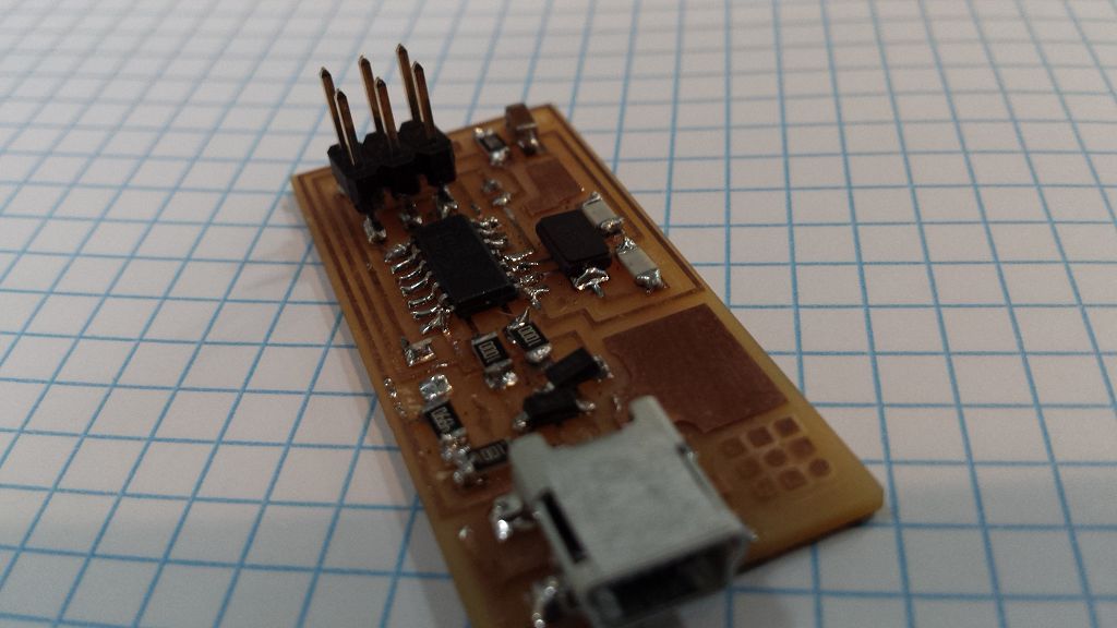
and my fab isp was ready!
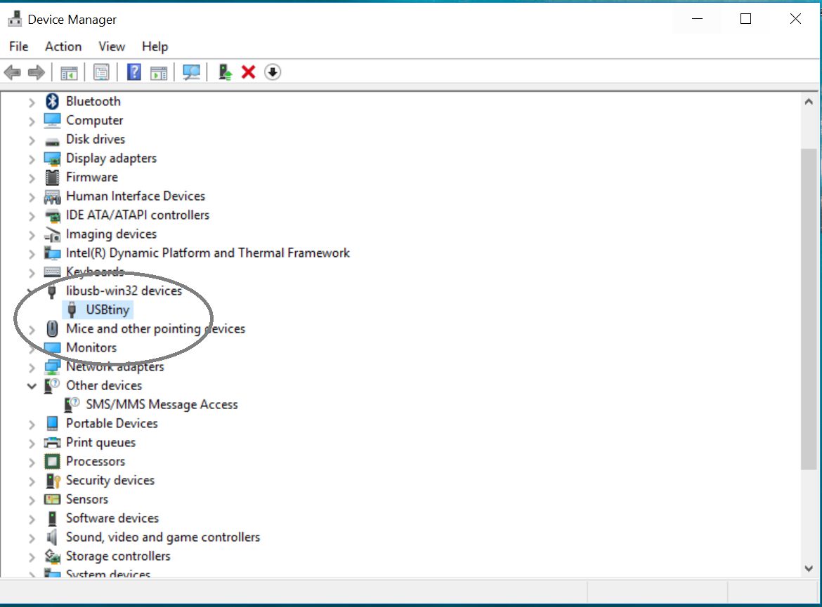
When I connected FAB ISP with my PC the device was detected.
Learning Outcomes
- Fabmodules is an opensource platform enabling students to generate toolpaths for milling and CNC machines.
- It is imperative that the PCB laminate is dead flat and properly afixed on the bed.
- Setup of drill bit is a very critical and extreme care must be exercised.
- Setup of (x0,y0,z0) is extremly important for optimal results.
- Soldering SMD components takes alot of practice to master. Avoid placing lump of solder on the pins.
- Use PCB layout and systematically check the traces to ensure the connectivity in electrical network using DMM.
Downloads
All required files are available Fab Academy website.

This work is licensed under a Creative Commons Attribution-ShareAlike 4.0 International License
Copyright © 2017 Muhammad Asim Ali
This work is licensed under a Creative Commons Attribution-ShareAlike 4.0 International License
Copyright © 2017 Muhammad Asim Ali