Muhammad Asim Samejo
Computer Controlled Cutting
For this week our assignment was to explore different 2D and 3D design softwares and create illustration of our final project using both of them .
The specific objective of this assignment is:
Group assignment
- Make lasercutter test part(s), varying cutting settings and slot dimensions.
- Cut something on the vinylcutter.
- Design, make, and document a parametric press-fit construction kit,
- Accounting for the lasercutter kerf, which can be assembled in multiple ways
Laser Cut Group Assignment
This was our first interaction with the laser cutting machine. We were very delight to know how useful this machine is in a variety of differnt ways. The object of this group assignment was to study the tolerence levels of the machine and to experiment with differnt values of laser power and speeds. For this assignment we made a basic pattern of rectangles. The parameteric design was prepared in Fusion 360 and then imported to Rhino in .igs format.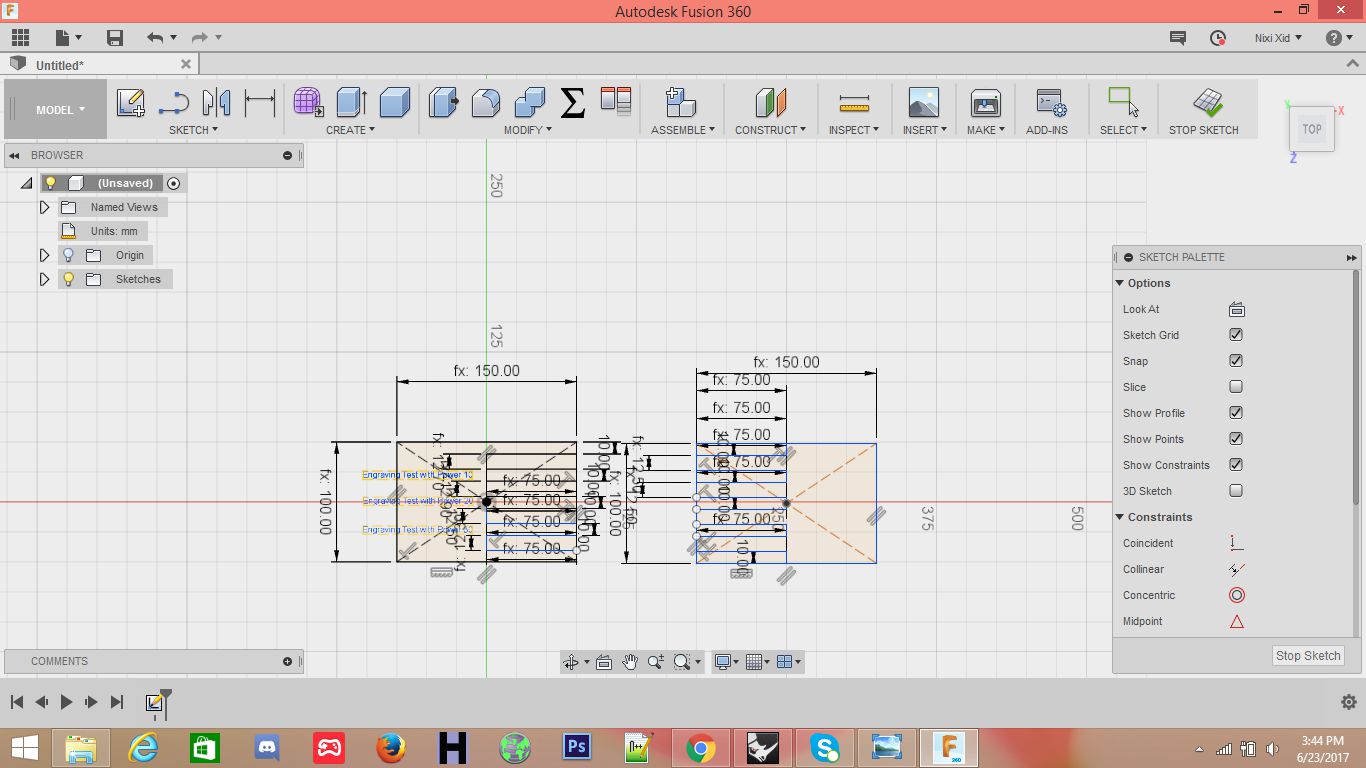
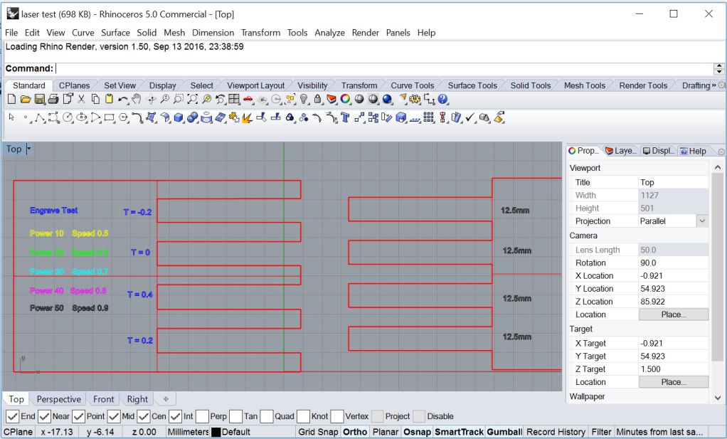
The file was imported is rhino and processed for laser cutting job.
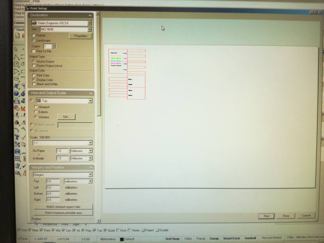
The job is sent to printer by simply clicking print icon. The print area and other properties can be configured using the following window.
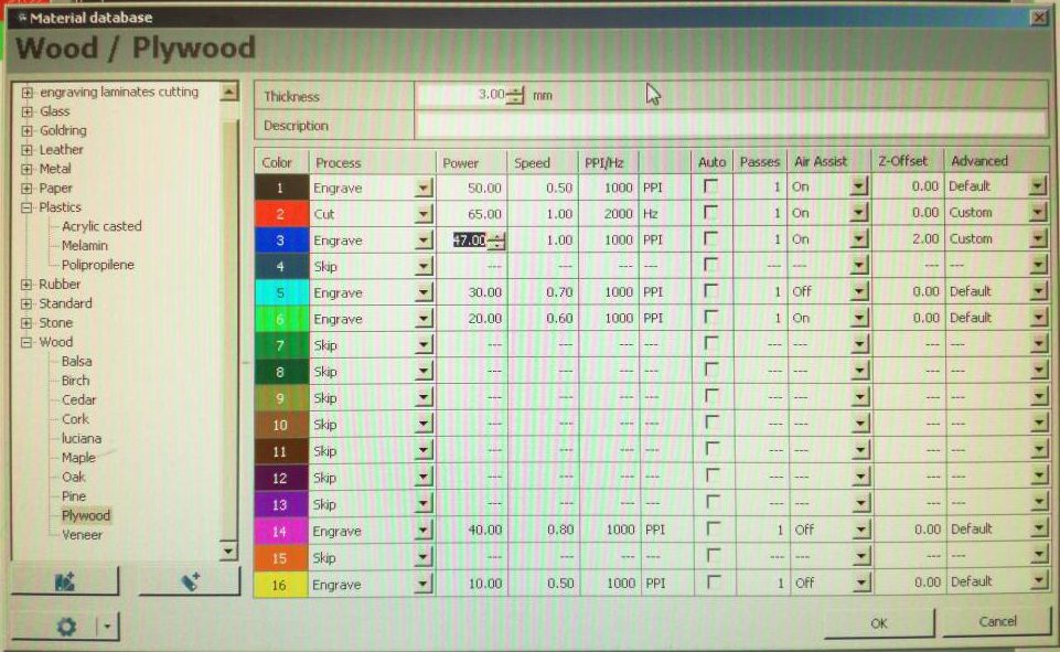
Different objects with different printing parameters can be combined in a single job. This is done by placing the objects on different layers and assigning different laser power and speeds to each layer. The menu used for this configuration is illustrated below
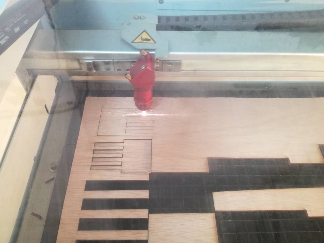
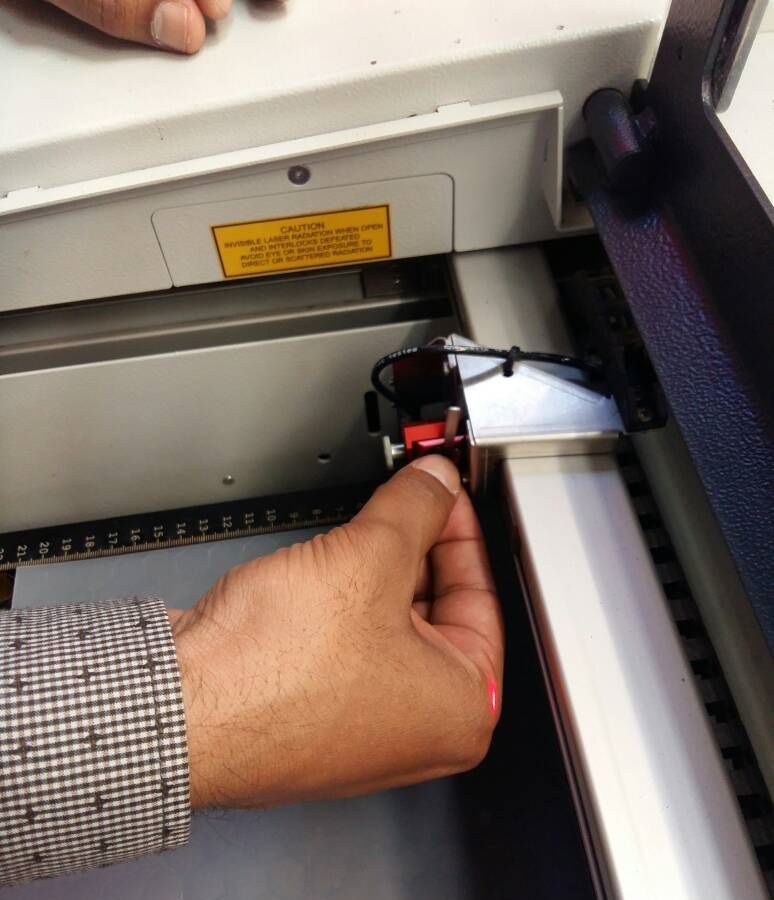
We started the print job by placing the stock on the print bed and setting the stock dimension in the Rhino Print options. Caliberation of laser z-axis must be performed with the help of metallic stub. After double checking everything print command was sent to the printer and it beamed away swiftly.
The Results
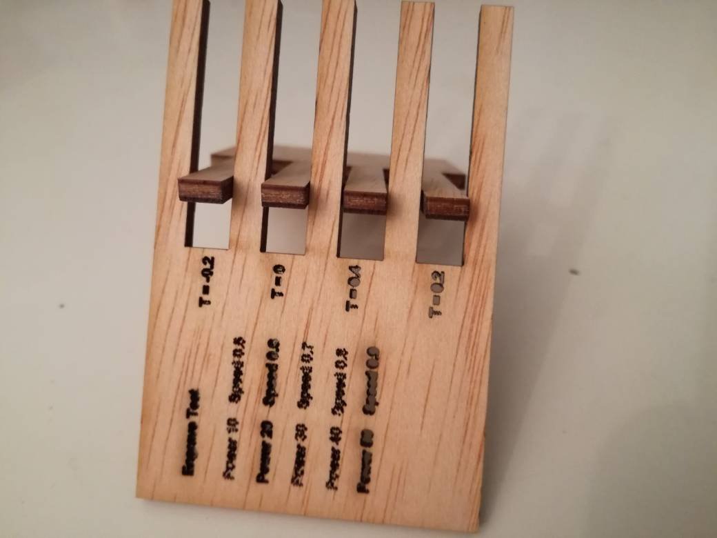
Following tolerances were considered -0.2mm, 0mm, 0.2mm and 0.4mm. The laser power cutting is set at 70. The results are illustrated below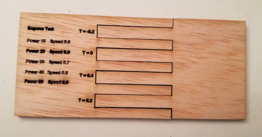
Since the tolerances are in sub millimeter scale the results are not prominent. However objects with lower tolerance would not fit tightly.
For engraving we tried different laser power and speeds. The results of engraving process are presented below
From our experience we come to conclude that although laser cutting is an effective way of cutting numerous items including paper, card-board, accrylic and plastics. However the laser power and speeds must be carefully choosen to avoid material melting or catching fire.
Vinyl Cutting
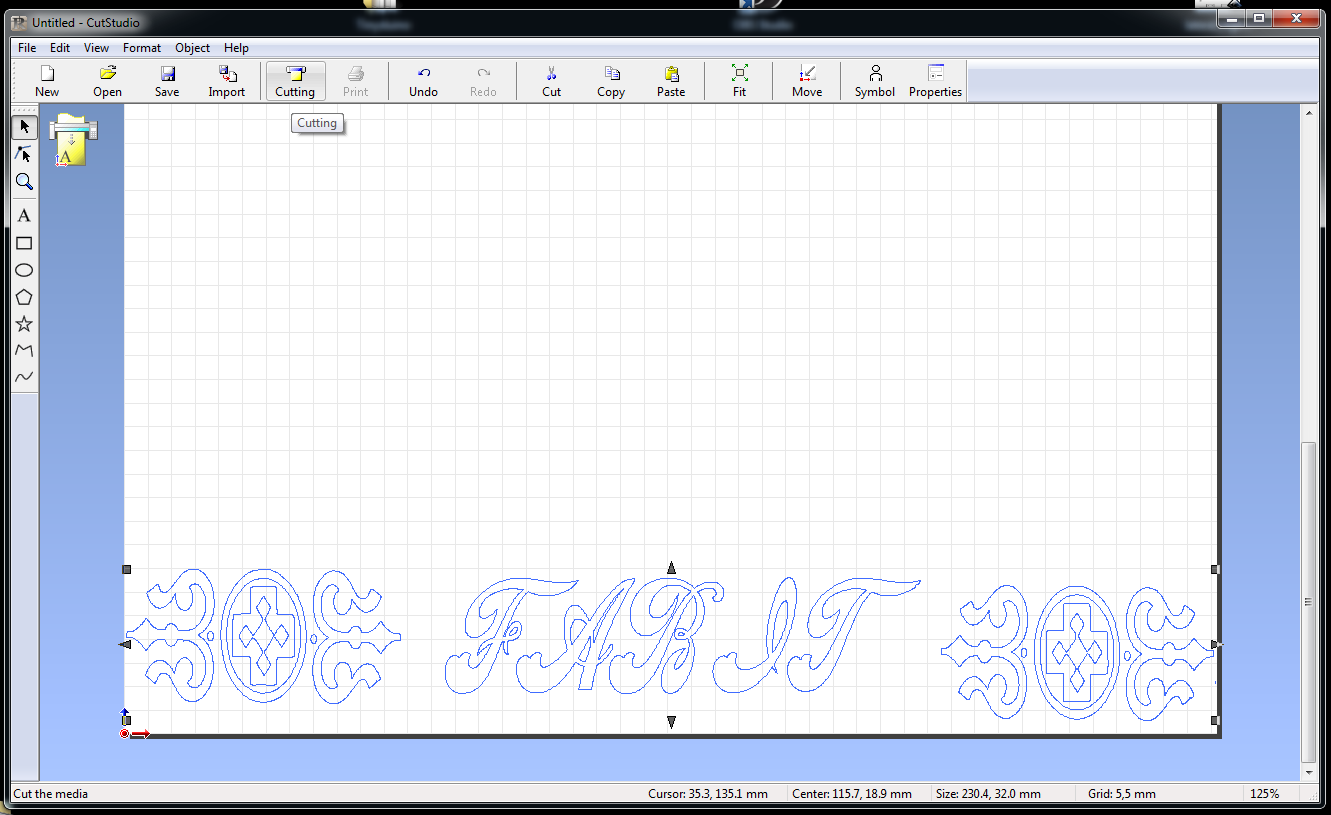
The process of vinyl cutting starts with the choice of the image. The vinyl cutter operates by cutting lines so they don't work with bit map images rather they require vector images with lines. For this assignment I wanted to do a simple text and text ornaments design. I created this design in my favourite graphics software MS Paint :)
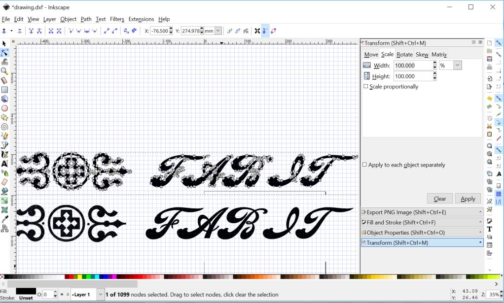
Once the design was ready I imported the design in inkscape. This software allows to trace any bitmap image in just a few clicks.
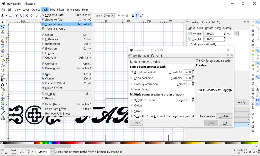
and the trace lines were obtained without any hassle. The quality of traces can be fine-tuned easily.
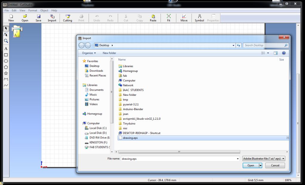
The traces can in stored in vector format. As santi suggested I saved them in .eps format. These images can now be directly opened in Roland Cutter software.
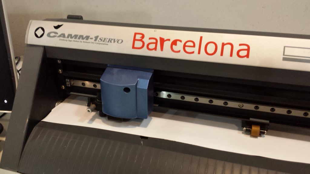
vinyl is loaded from the back side, tricky tricky tricky..
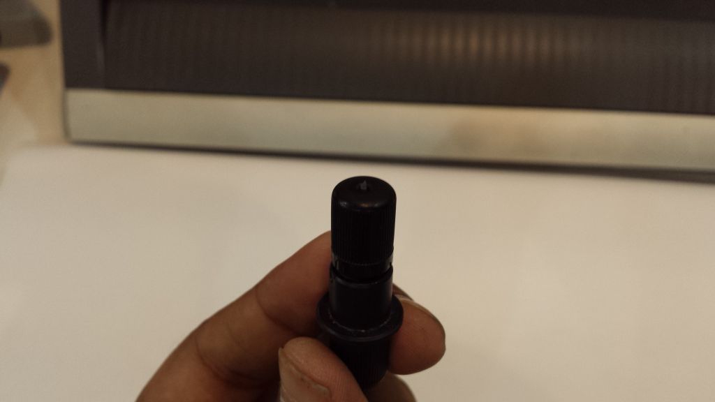
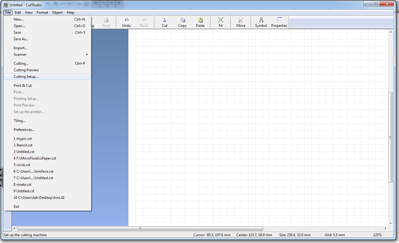
adjust the cutter depth to suit the vinyl material
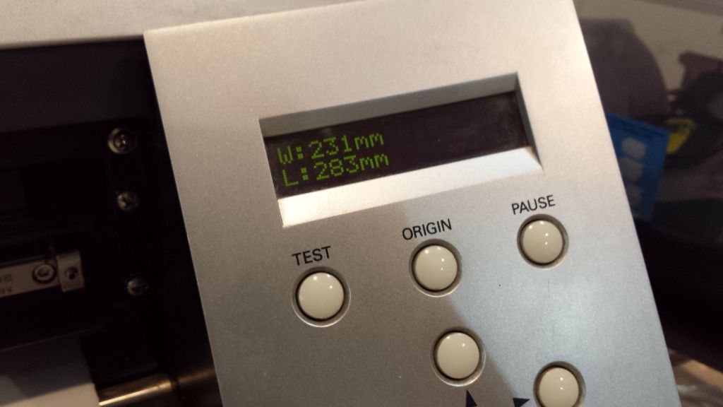
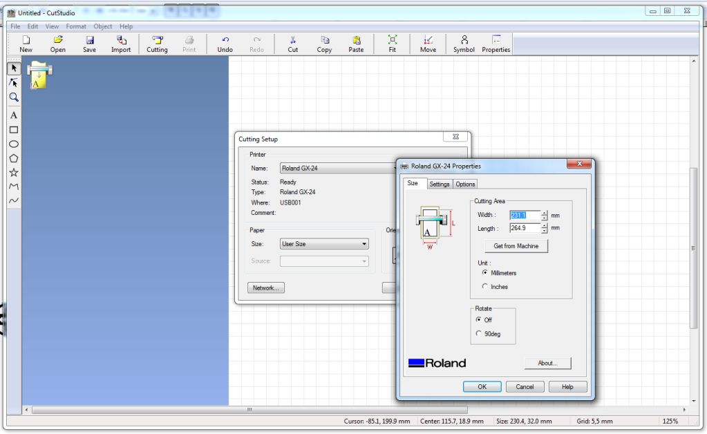
the machine obtains the dimensions of vinyl automatically
expert eye is needed to spot the cuts
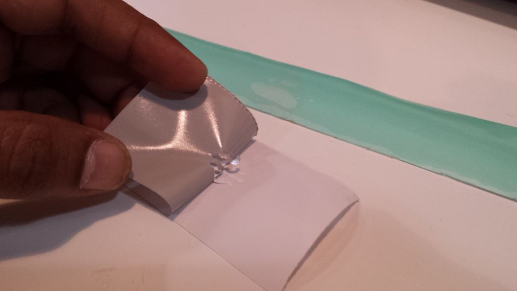
gently peel off the excess vinyl leaving the desired material intact
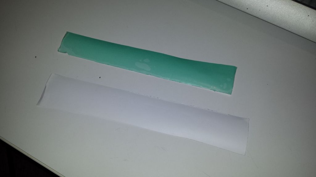
plug the remaining material on transfer sheet. your sticker is now ready.
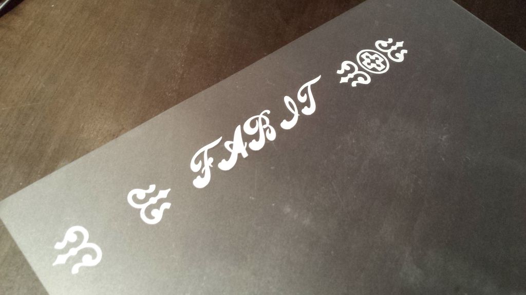
the sticker on a plastic sheet.
Laser Cutting
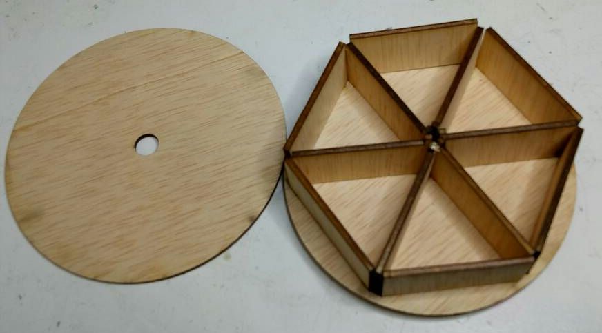
For this assignment I wanted to make a simple spice box. This box is very handy as you can have all your spices in one place.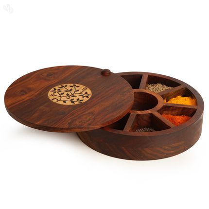
Since we moved to Barcelona we are cooking food for ourselves; I thought this will be a good thing to have.
I am very new to Fusion 360 and making my way through design techniques. To design this object I exploited the symmetry property of the top , bottom lids and partition walls.
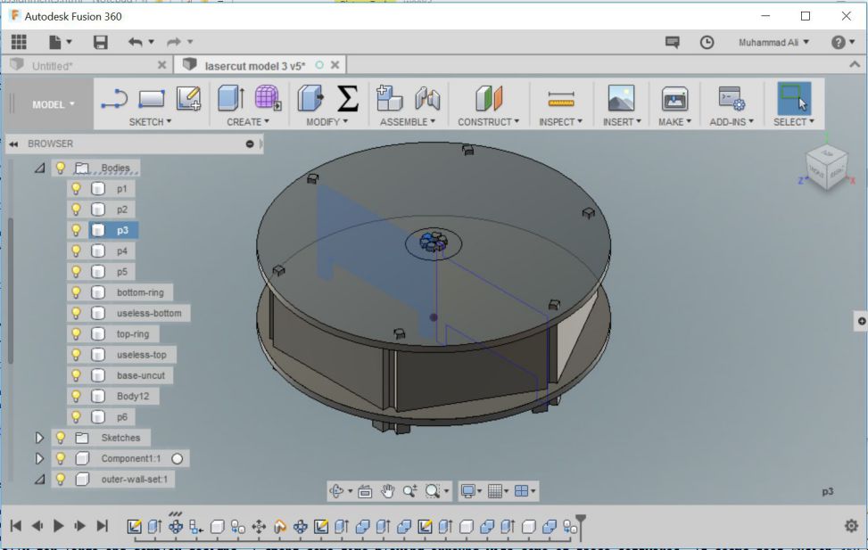
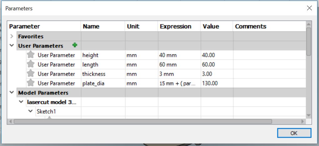
This is a paramertic model, the variables which I defined are the diameter of base plate, height and length of the partition walls, thickness of the plywood and so on. the design was created instantly using the circular pattern tool. I used combine tool in modify menu to obtain required details.
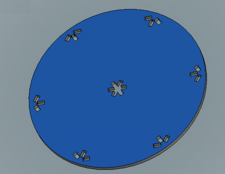
To let the partitions stick to the base I created slots in the bottom plate.
The source files can be found here. The object were exported to Rhino for laser cutting the design, the imported file was converted in to 2D objects using make2D commands and re arranged to minimize occupied space.
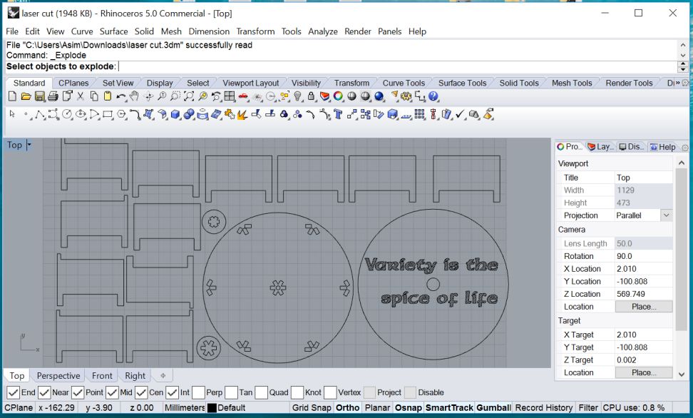
Grouping line segments in together in Rhino simplifies the laser cut job. The cutting and engraving jobs are organized in different layers and executed with different parameters. On the lab work station I loaded my file in Rhino and sent the files to laser cutter with Print button.
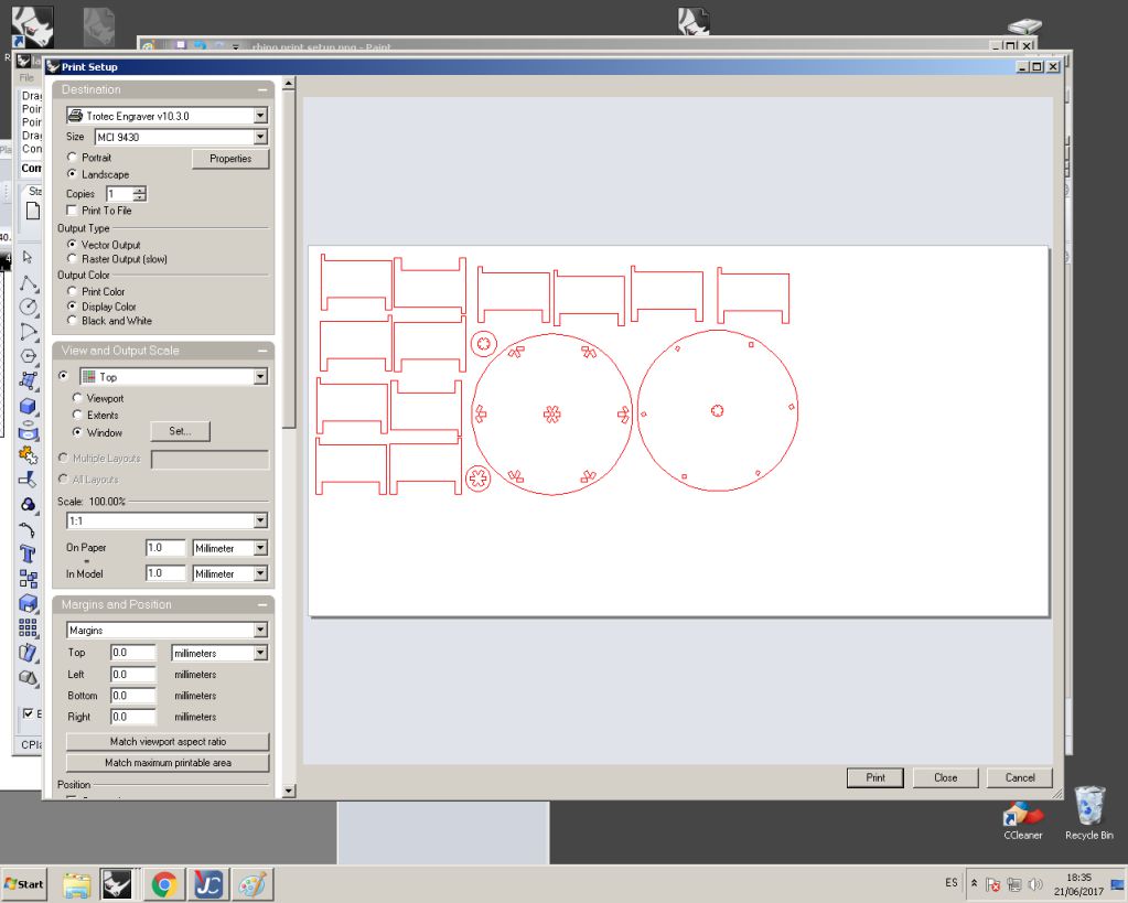
The following window presents itself where the options for print area, printing scale can be configure when we proceed to print
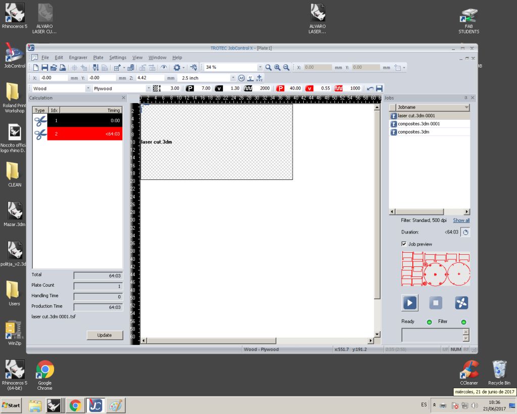
the trotec software interface presents itself with active print jobs and laser settings. The process of printing starts with caliberation of laser using metallic contact.
The laser power and speed need to optimized for the material and job at hand
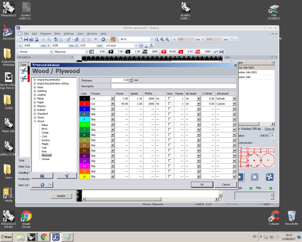
Data of stock material and required parameters is already available in the software
All laser cutting jobs are performed by leveraging three fundamental parameter
Power |
Speed |
Frequency PPI |
I found here suitable explanation of these parameters which I have reproduced here:
Power Setting
- Higher power burns deeper. Too much power sacrifices detail. Has no effect on running time.
- Lower power burns shallower. Too little power sacrifices detail. Has no effect on running time.
Speed Setting
- Higher speed saves time. For same speed it burns shallower and reduces detail.
- Lower speed increases time. For same speed it burns deeper but too deep may reduce detail.
PPI Setting
- Higher frequency increases the burning or melting effect. Produces finer detail if speed is not too fast. Has no effect on running time and very little effect on depth.
- Lower frequency decreases the burning or melting effect. Reduces image detail if set too low. Has no effect on running time and very little effect on depth. Very low settings are used to perforate the material.
Rule of Thumb
- Doubling the power doubles the depth and halving the power halves the depth.
- Halving the speed doubles the depth and doubling the speed halves the depth.
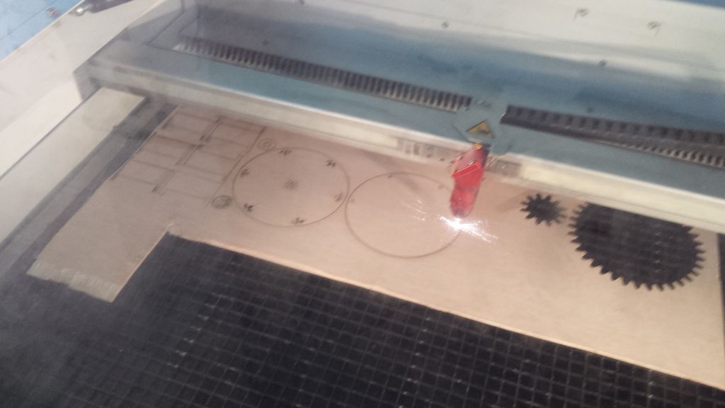
As per opinion of our instructor (Santi) it make sense to do a trial laser cut on card board. So I did a test with card board
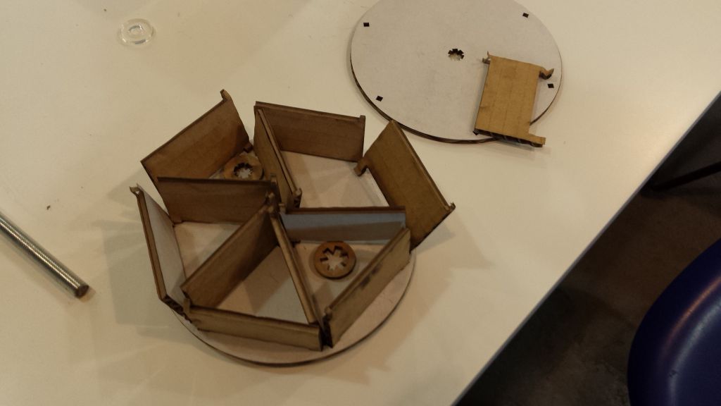
and the results were just about encouraging. Then I did the second iteration with plywood.
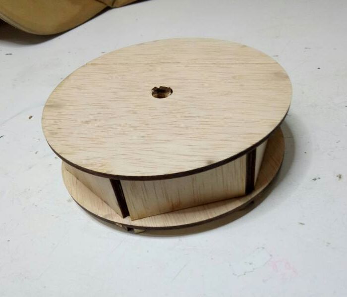
The joints were snug and sturdy. However the partitions did offer some resistance as I tried to place partitions together.
Learning Outcomes
- Laser machines provide superme accuracy in cutting objects however acouple of (card-board) test cut should be made to validate design and optimize laser power and speeds.
- Carefully planning job with good choice of Power, Speed and Frequency settings can optimize results and job time.
- Grouping line segments together in Rhino simplifies the laser cut job.
- Vinyl Cutting is a very effective way of making professional stickers and artwork. However cutting vinyl with details (afew millimeters apart) are very difficult if not impossible.
Downloads
Autodesk Fusion 360 files here.find all source files here.

This work is licensed under a Creative Commons Attribution-ShareAlike 4.0 International License
Copyright © 2017 Muhammad Asim Ali
This work is licensed under a Creative Commons Attribution-ShareAlike 4.0 International License
Copyright © 2017 Muhammad Asim Ali