Muhammad Asim Samejo
Networking and Communication
The assignment for this week was to make devices communication with each other. Specifically
- Design and build a wired &/or wireless network connecting at least two processors
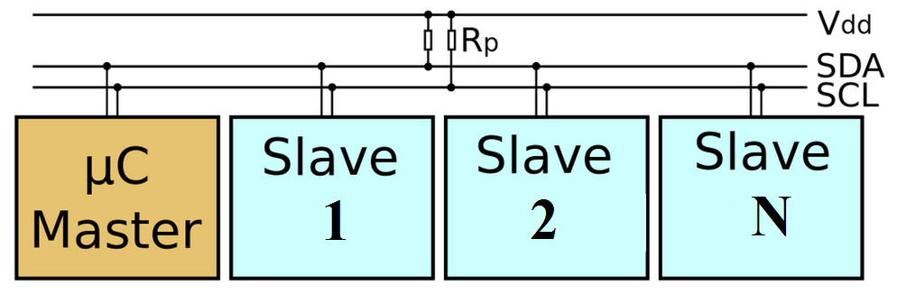
This is a very important assignment as this serves as a crucial segment of my final project. My objective was to design a network of micro-controllers over i2c protocol. The salient features of this protocol include:
- Can connect upto 120 devices using a pair of wires ( bus topology).
- Supports data-rate ranging from 100kbps to 2 Mbps.
- Useful for sensor networks
- Supported by almost all micro-controller families, loads of libraries and well documented.
Most of large pin-out micro-controllers have dedicated i2c ports for straight forward use. Atmel AVR Attiny family have no dedicated pins for i2c. However, using USI peripheral it is possible to setup i2c interface.
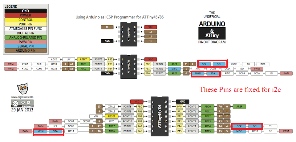
Attiny family supports i2c interface only at certain pins.
Another possible way to implement i2c interface is bitbanging method. This method manually implements transmission of data through manipulation of port. Unlike Universal Serial Interface (USI) ports bitbang technique can be used on any available port of the micro-controller. This code is available at Fabacademy website. However I realized that this technique may not be suitable for complex network which I am intend to design.
The master trigger slaves one by one and they turn on thier light for specified duration. I implemented the circuit schematic and PCB layout in Eagle and milled the PCB through steps already discussed in assignment 4, 6 8 and 12.
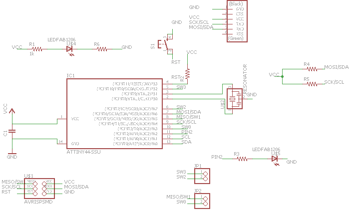
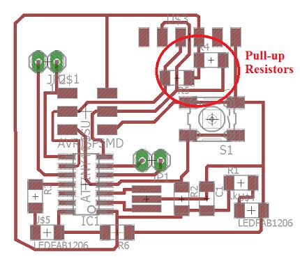
The electrical schematic
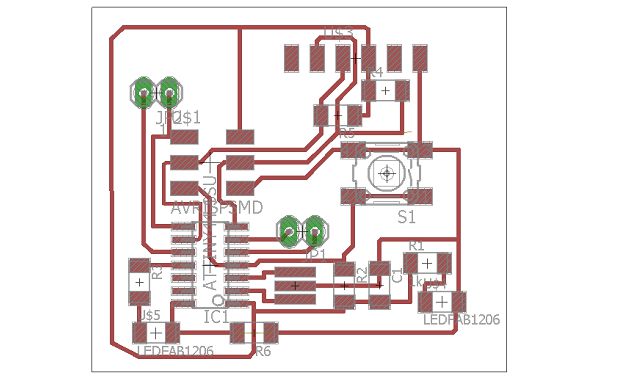
The PCB layout
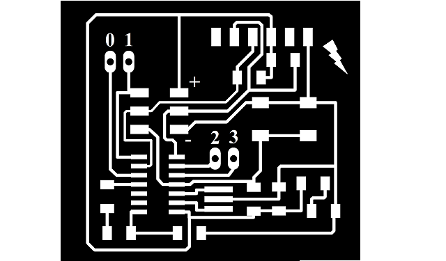
Traces for fabmodule

Board cut for fabmodules
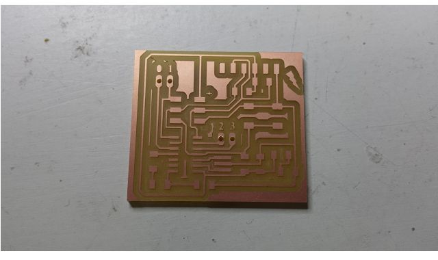
Mill fresh PCB
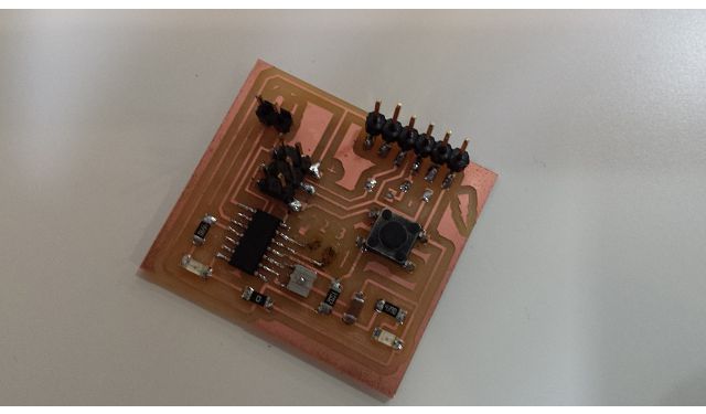
PCB after stuffing
As illustrated in the conceptual network diagram the are SDA and SLC are tied to Vcc. This connection doesn't neccessarily need to take place at Mater device rather it can take place anywhere across the network. So in my PCB I have a provision to tie i2c pins by simply applying suitable resistors.
In a typical scenario a master can write instruction to and read data from slave devices. There exist several libraries supporting plug-n-play support for i2c protocol. For Atmega family micro-controllers wire library is used since they have dedicated i2c ports. In this implementation I have used tinywireS library. This library (I think) is used to setup i2c slaves.
I looked up the Fabacademy website and found some implementation of i2c transmission systems. The links are provided here:
I found basic code from these pages which I have modified to work in my setup.
//LOES SLAVE VOOR T44 j.e


#include <TinyWireS.h>


#define I2C_SLAVE_ADDR 0x26          //define slave address, 2nd slave has address 0x27

#define LED1_PIN 2 //PA2 (pin11)

void setup(){


pinMode(LED1_PIN, OUTPUT);


 Blink(LED1_PIN,2);                    // show it's alive, blink void twice


 TinyWireS.begin(I2C_SLAVE_ADDR);       //initialize I2C lib and setup slave address

}


void loop (){


  byte byteRcvd = 0x00;

  if (TinyWireS.available()){    // get I2C input from slave

          digitalWrite(LED1_PIN, HIGH);

          delay(100);

    byteRcvd = TinyWireS.receive();  //get the byte from master, returns next byte in received buffer

      if (byteRcvd == 0){

        digitalWrite(LED1_PIN, !digitalRead(LED1_PIN));

        delay(200);

      }


  if (byteRcvd == 0x01){                //is the byte equivalent of decimal 1

        digitalWrite(LED1_PIN, !digitalRead(LED1_PIN));

      delay(200);

      }

   }


  }


void Blink(byte led, byte times){       // poor man's display

  for (byte i=0; i< times; i++){

    digitalWrite(led,HIGH);

    delay (250);

    digitalWrite(led,LOW);

    delay (250);

  }

}
// Wire Master Writer

// by Nicholas Zambetti


// Demonstrates use of the Wire library

// Writes data to an I2C/TWI slave device

// Refer to the "Wire Slave Receiver" example for use with this


// Created 29 March 2006


// This example code is in the public domain.


#include < Wire.h >


void setup() {

  Wire.begin(); // join i2c bus (address optional for master)

}


void loop() {


  Wire.beginTransmission(0x26); // transmit to device #26

  Wire.write(0x00);              // sends one byte

  Wire.endTransmission();    // stop transmitting

  Wire.beginTransmission(0x27); // transmit to device #27

  Wire.write(0x00);              // sends one byte

  Wire.endTransmission();    // stop transmitting

  delay(2000);


  Wire.beginTransmission(0x26); // transmit to device #26

  Wire.write(0x01);              // sends one byte

  Wire.endTransmission();    // stop transmitting

  Wire.beginTransmission(0x27); // transmit to device #27

  Wire.write(0x01);              // sends one byte

  Wire.endTransmission();    // stop transmitting

  delay(2000);


}
The diagram on my implementation is illustrated below: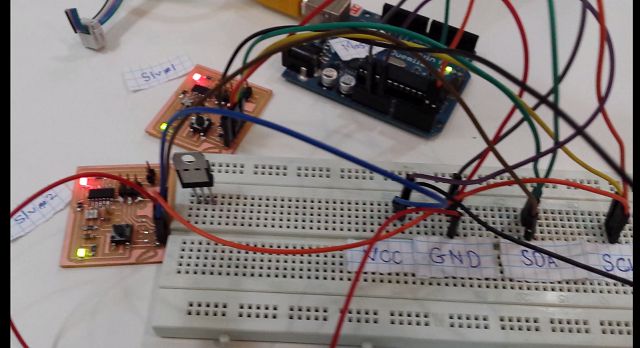
Arduino Atmega328 as master and 2 Attiny 44 slaves connected to i2c bus.
I also noted that it is not possible to program while system is connected to an I2C bus. Since MOSI and SLK pins of ISP are connected to SDA and SCL pins of I2C network.
A video illustrating successful operation of the system.
Learning Outcomes
- I2C protocol is a easy and handy protocol capable of establishing data network between several devices.
- Tinywire library provides out-of-box technique to setup I2C slaves.
- From little experience I have realized that the timing of instructions to be passed from master to slave is critical.
Downloads
find all PCB layouts here.find all Source files here.

This work is licensed under a Creative Commons Attribution-ShareAlike 4.0 International License
Copyright © 2017 Muhammad Asim Ali
This work is licensed under a Creative Commons Attribution-ShareAlike 4.0 International License
Copyright © 2017 Muhammad Asim Ali