Computer Controlled Machining
This week is make something BIG through computer controlled machining processes this means first to design your model in software than you have to use the machine that is interfaced with the computer will extrude out the model in 2.5 D. In this regard I was assigned to design something BIG. I thought of designing a cloth rack with open drawers as for as selection of software was concerned I felt comfortable with Autodesk Fusion 360 and mahine in the lab for the developing this design was CNC Machine
Individual Assignment
Make Something Big (on a CNC machine)
Introduction about CNC Machine
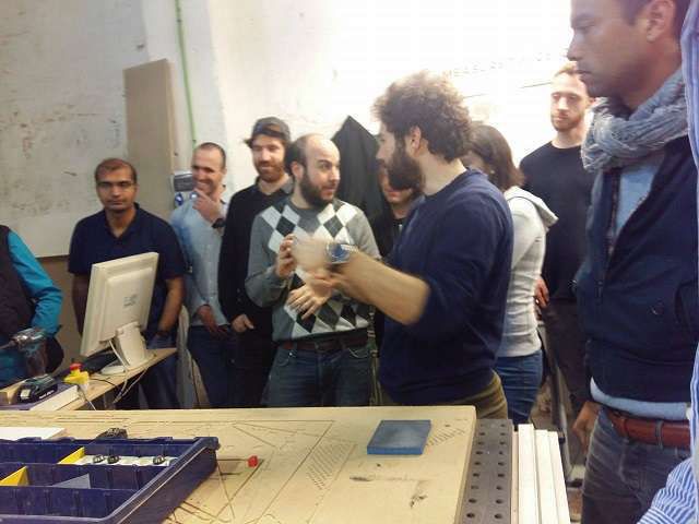
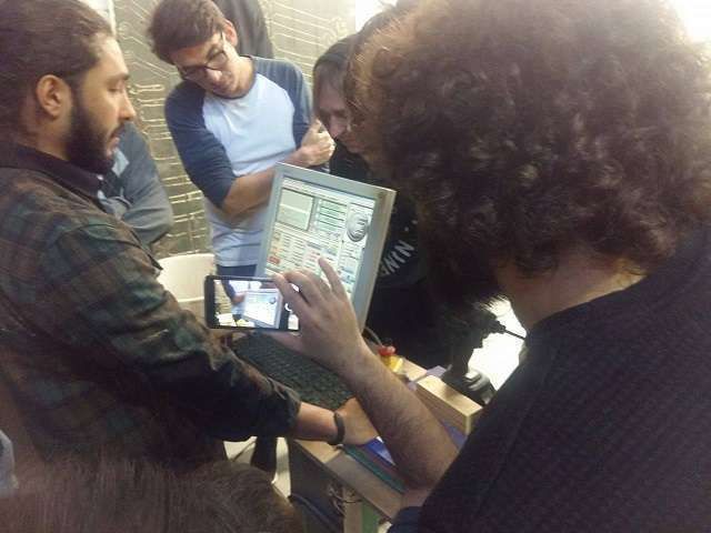
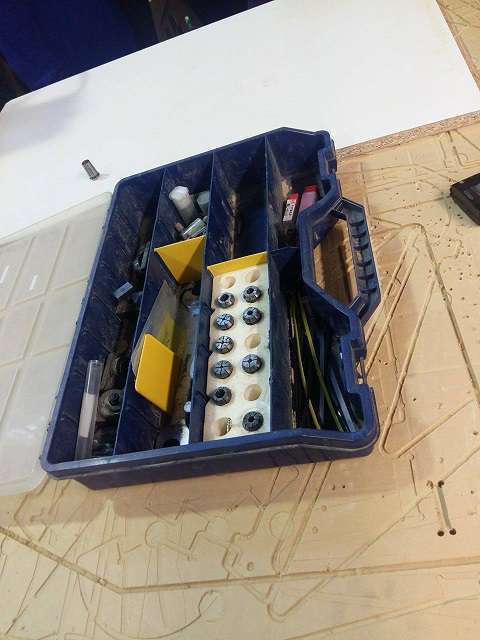
The CNC machine was totaly a new addition to my technical dairy. so a detail demonstration was given by the instructors and responsible persons for this machine and we came to know about the Precautions,Manual Instructions before Using, Tool Identification and User interface to controll the XYZ parameteres of the milling. here some snapshots of whole demonstration
.
My design
I designed a cloth rack with four open drawers the design is quite simple and usefull for the domestic home usage. To achieve this target I was given a wooden sheet of following dimensions
Length = 2500 milimeters
Width = 1250 milimeters
Thickness = 15 milimeters

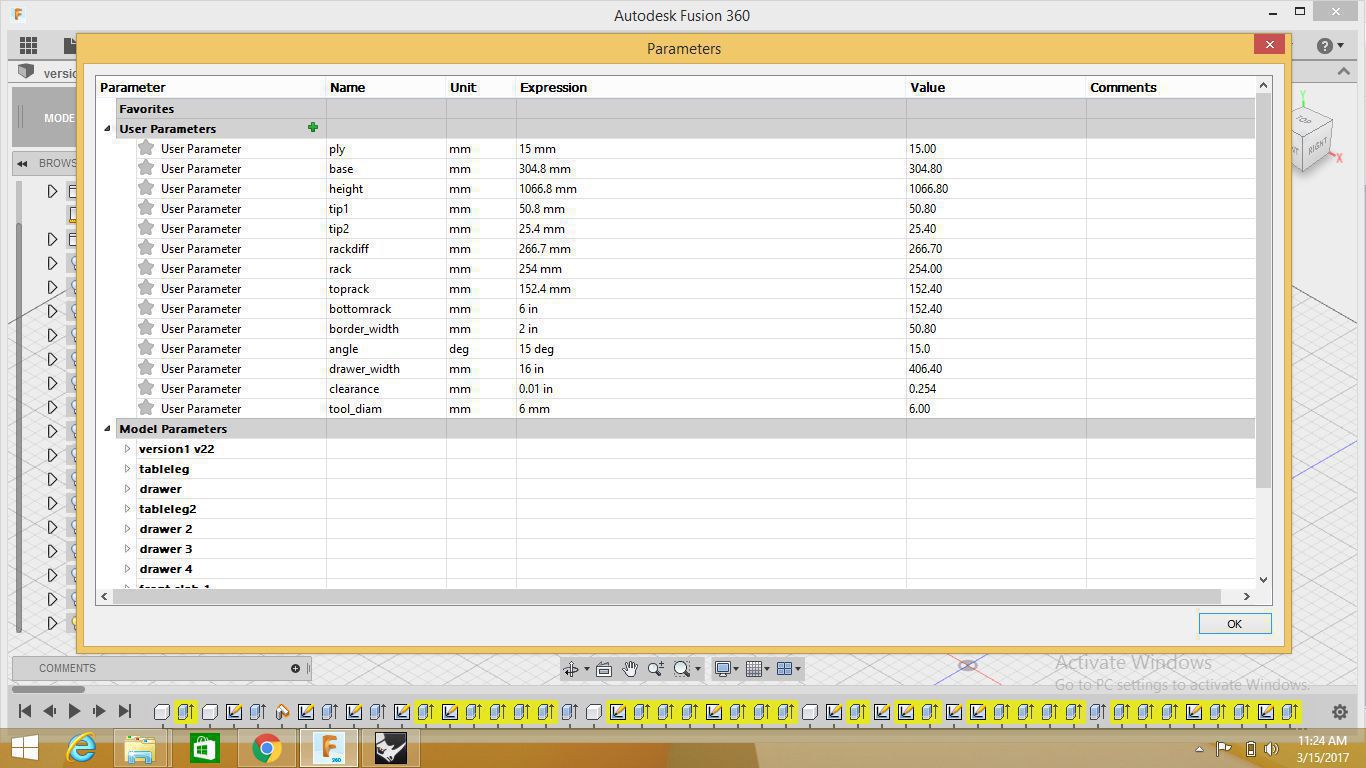
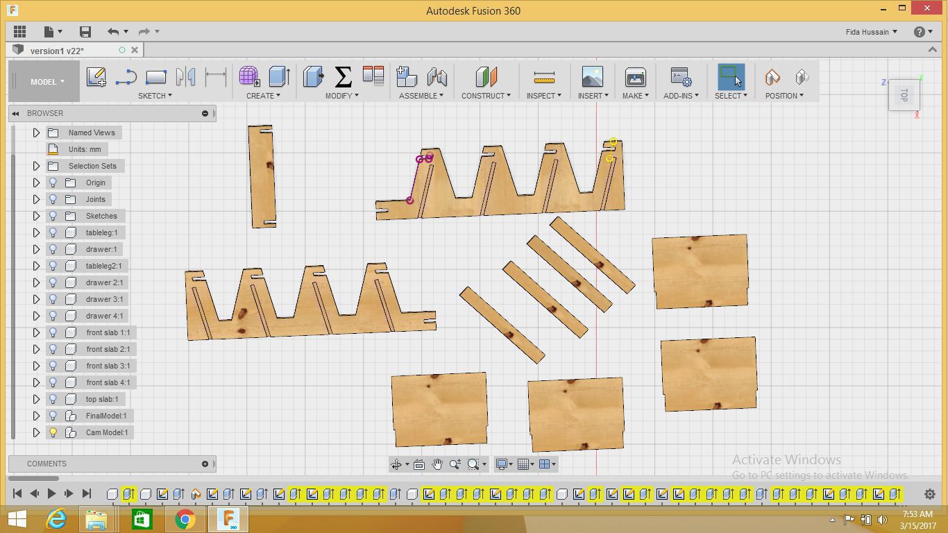
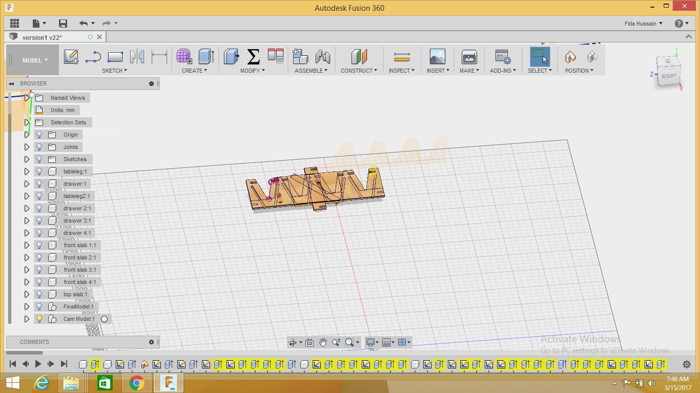
Here is my design in fusion 360 a ready model and one of the snapshots is showing the parameters I declaired for each element I tried to make the design so far a parametric
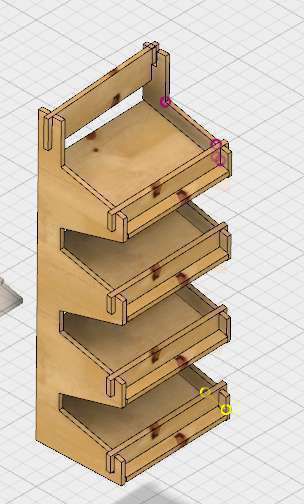
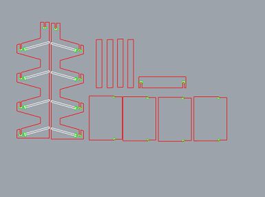
The different views of my design are shown in the pictures below I designed four types of elements in this design two legs (left and right) with the height of 1066 mm and 305 mm of base to hold the drawers, four slabs of th measurment of distance between two legs to put on cloths or other stuff four front slabs of small size to hold the stuff on the main slab and one top slab to grip two legs
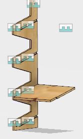
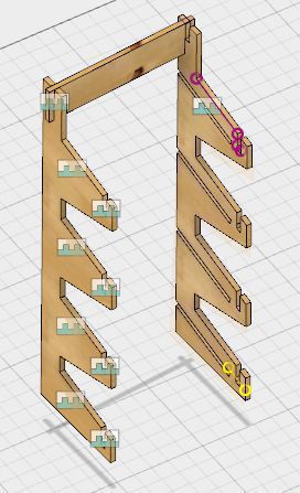
Here are some snapshots showing the different elements of my design and next I assembled all the elements together to generate the dxf file.
After finishing the design on Fusion 360 I got ready to mill the board and due to some massive reservations at milling machine in BCN campus I was recommended to go for Vallduara campus. This campus was named as self sufficient Lab of IAAC so it was considered as integral part of IAAC BCN.
Generating GCODE
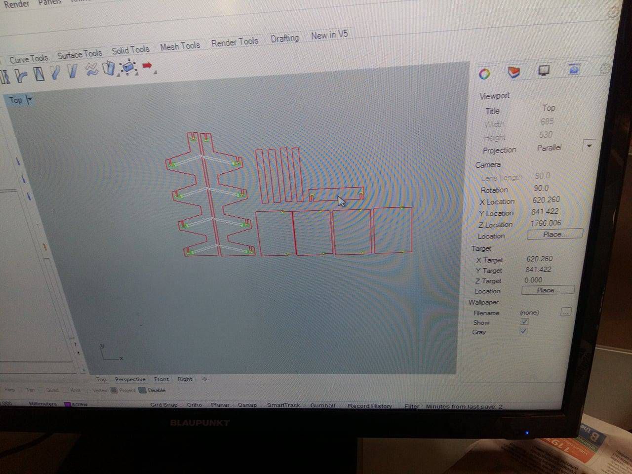
Next day I reached Valldaura and started there the remaining work for my file to get ready for the milling, at first I export my file in rhino cam and then went for customizing the required file. I m really thankful to Arnau who guided me the rhino cam process for the file. Under the guidelines of Arnau I started to understand the layer process my design was required to be placed with different layers i.e screw layer(in this layer we decided to put screws on different possible places of the board to make it unmovable while milling, in my case I put ten screws on my board), dog bone layer(This layer is responsible to achieve 90 degree curve inside the design object, in my case I placed 48 dog bone holes), Inner cut layer (I did not need to cut inside the baord as for as my design was concerned), outer cut layer(Actually this out cut layer is resposible to cut the boundaries of the design). I bye pass the pocket layer as my design does not contain any pockets as shown in the images below.
Tool selection
After this all process I need to select the tool size, as per directions and size width of the board I selected the 6 mm flat tool for whole milling process. this is shown in snap below.
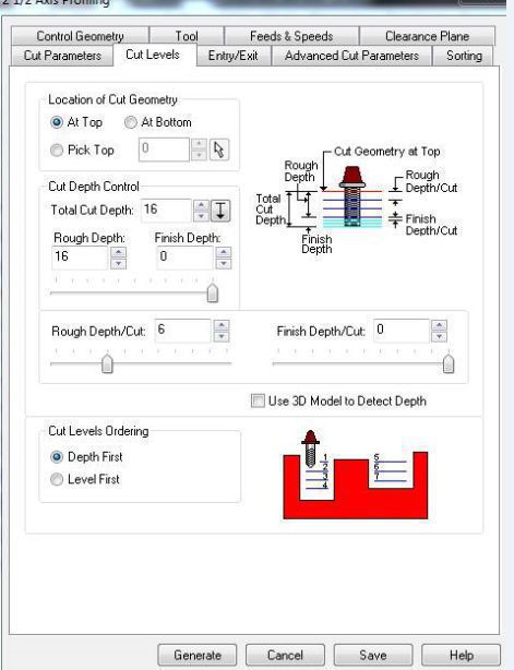
Setting cutting depth
The width of the plywood I was provided with was 15 mm so to cut through the board I decided to put 16 mm as cut depth to achieve full through cut of the board at every point of milling and in RhinoCAM we can set this setting in setup window as shown below.
More settings
For more settings follow the video I uploaded on youtube
Simulation
For Simulation I have uploaded the video on youtube
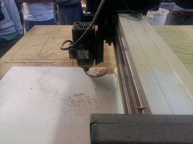
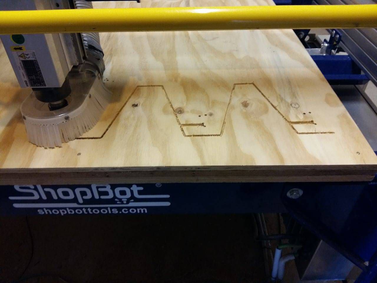
Milling
in valldaura campus I found Shopbot machine to mill my design. as per suggestions given by Arnau I went under the following steps.
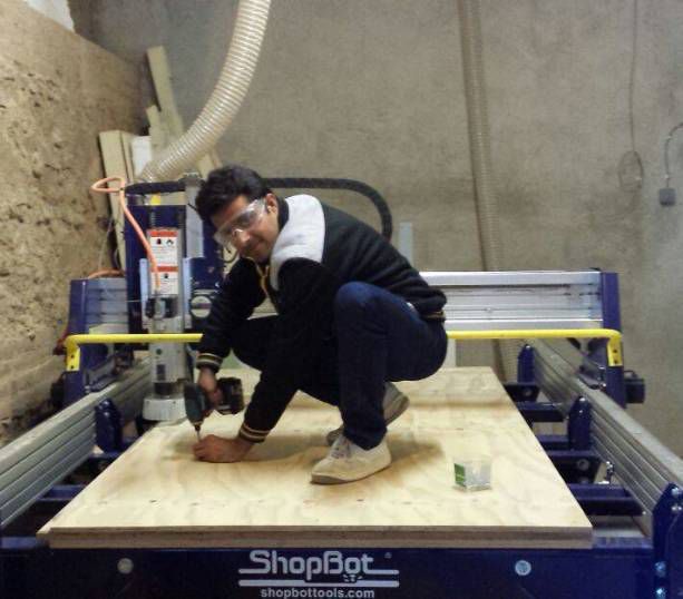
- Very very important to wear the safety glasses
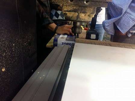
- Cleaning of the board if any waste material is left due to previous mill and other benefit of cleaning the surface is perfect fixing of plywood to avoid the height variance of the board
- To fix the 6 mm tool in the spindle
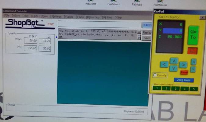
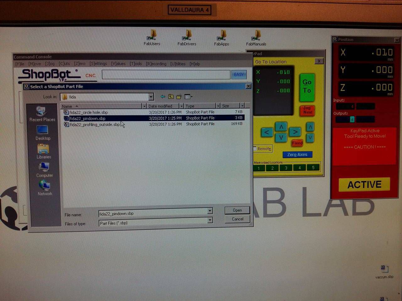
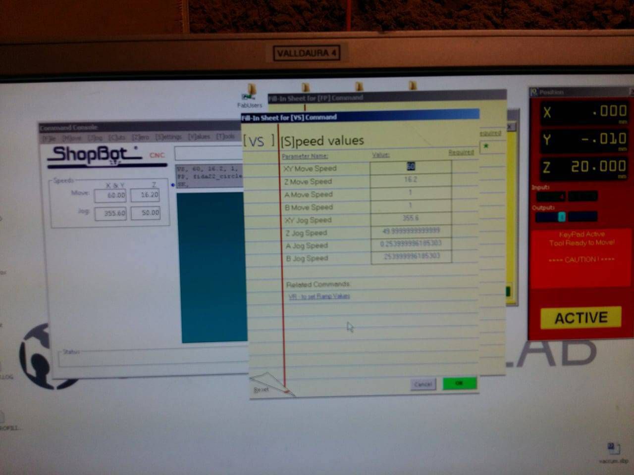
- Opening the software to set the (X,Y,Z)=(0,0,0)
- Sending the GCODE files one by one to machine
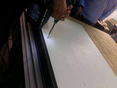
- Testing and sending GCODE to drill screws
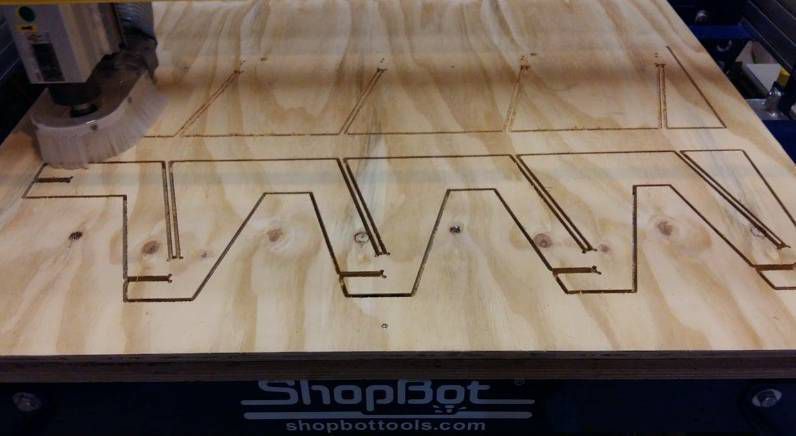
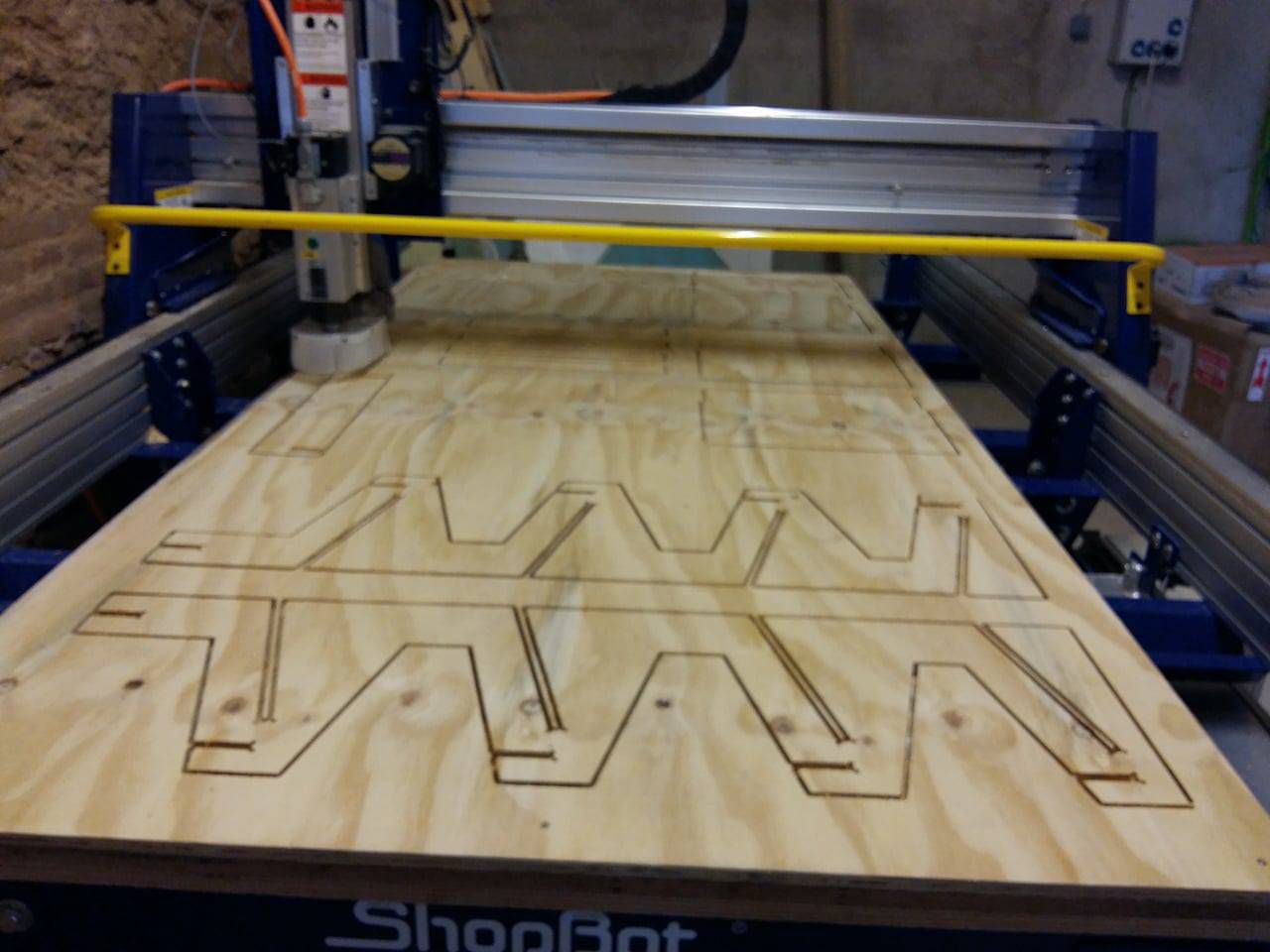
- Testing and sending GCODE file for milling
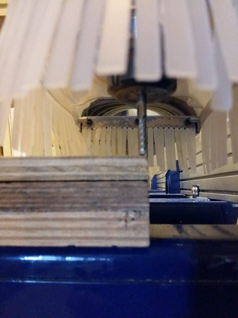
- Milling process in progress
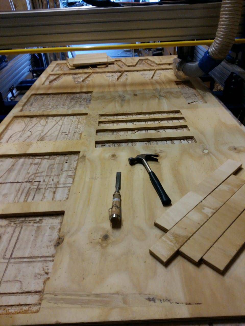
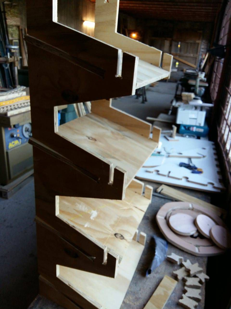
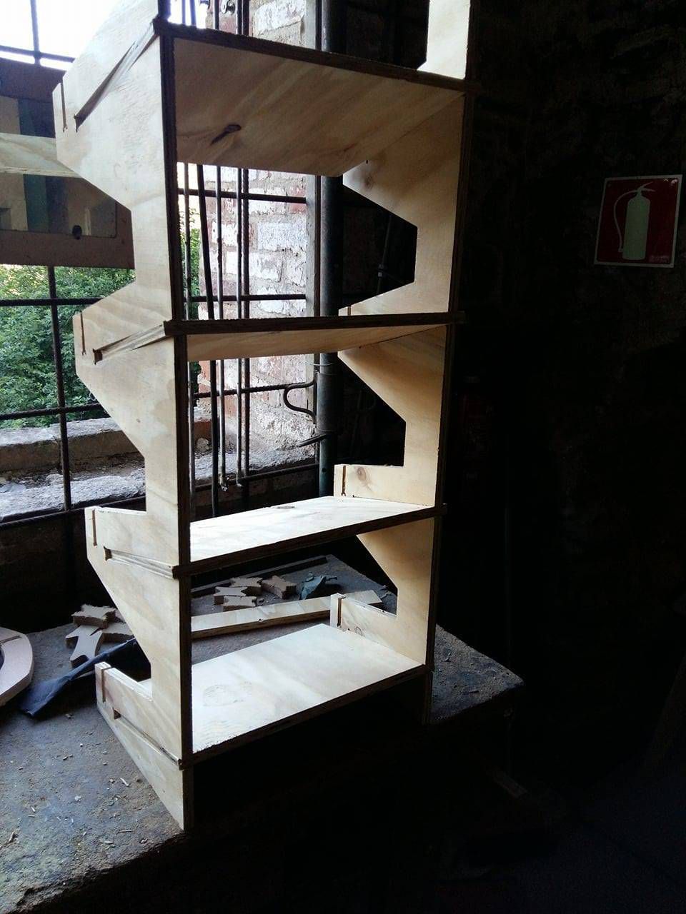
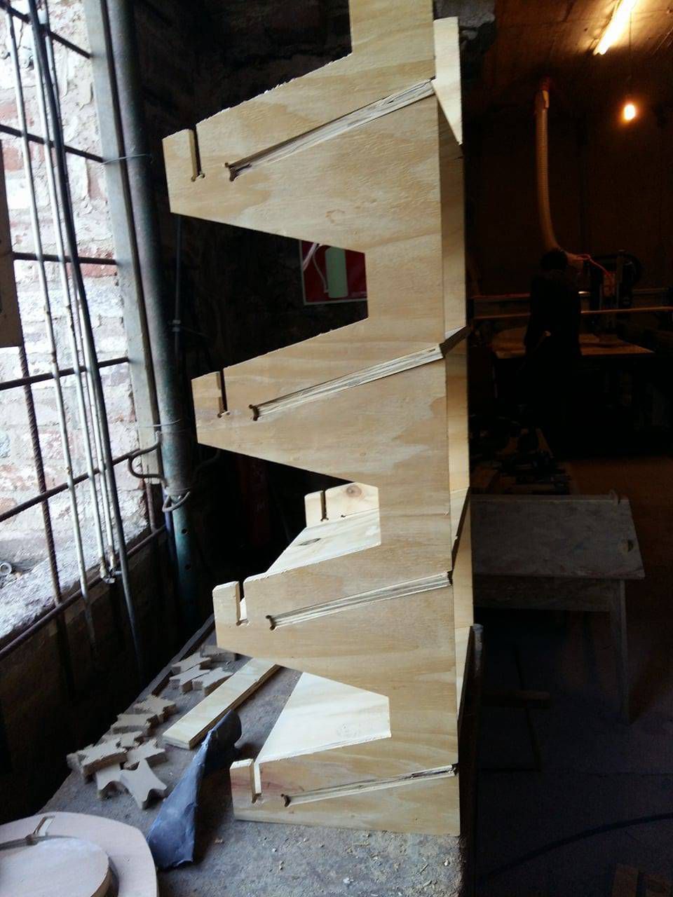
- Finally taking out the drilled parts and assembling the Model
- Hero shot of the Model

Download the relevant files of the assignment