Electronic Production
Task Assigned
Make an in circuit programmer by milling the PCB, then optionally trying other processes.
Learning Outcomes
- Describe th process of milling, stuffing, debugging and programming .
- Demonstrate correct workflows and identify areas for improvement if required.
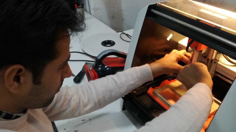
The very first step is to mill the Printed circuit board, as this board has surface full of copper so through milling we are basically remove some copper areas from the surface of the board to recognize traces of the signal and pads for embeding the SMD components, over all milling the board is to recreate the lay out of circuit we want to produce. to mill the board I used Roland SRM 20 available in the lab.
Important precausions before milling the board
1. Clean the machine properly using brush and taking out the tray down the machine to make it empty.
2. Removing the double sided tap from the board to be reused
3. Try any technique to assure that the board surface is traight not curved.
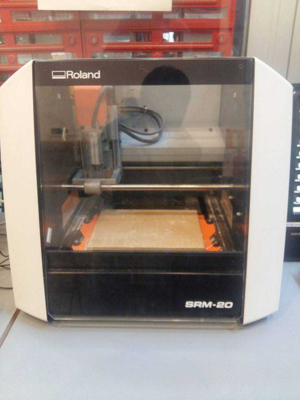
Now the Roland machine show above in the image is ready for milling the board
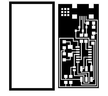
In the very next step I downloaded Neil's FabISP's image files for the traces and outline as shown in figure below.
After downloading the image files of traces and outline now its time to generate the .rml file in this regard I went through FAB modules
Generating .rml files for traces and outine
1. Traces
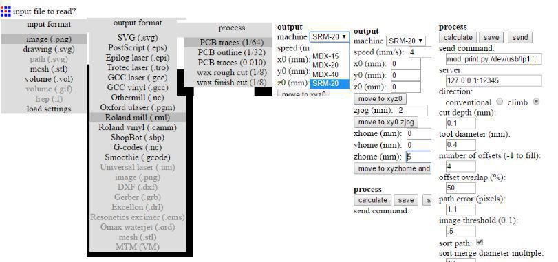
To generate the rml file for the traces I followed the steps as shown in image below from left to right
2. Outlines
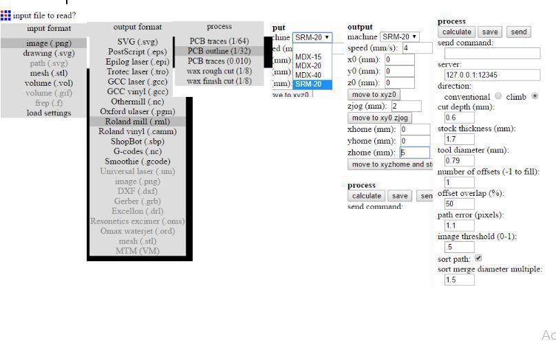
To generate the rml file for the outlines I followed the steps as shown in image below from left to right.
Milling
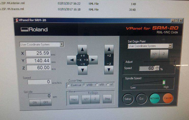
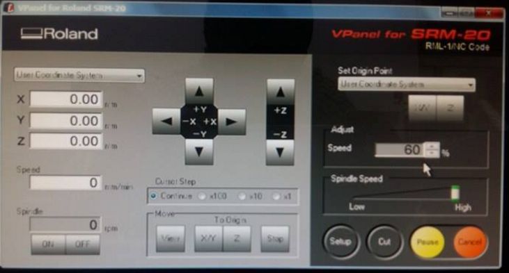
Now its time to mill the board for this I have to open the Vpanel which is the GUI to execute the process parameters for Roland milling machine. The main thing here is to set the XY and Z to their respective origins i.e (X,Y,Z)=(0,0,0).
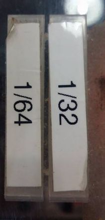
Selection of the milling tool is very serious part of the whole process here we are available with two types of milling tools one of them is 1/64 which is used for milling the traces and the other one is 1/32 which is used to mill outline. change the tool very carefully after every milling. I change the tool 1/64 for the traces first as shown in images below
Now press cut and add the rml file one by one at first traces and than outline.
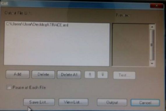
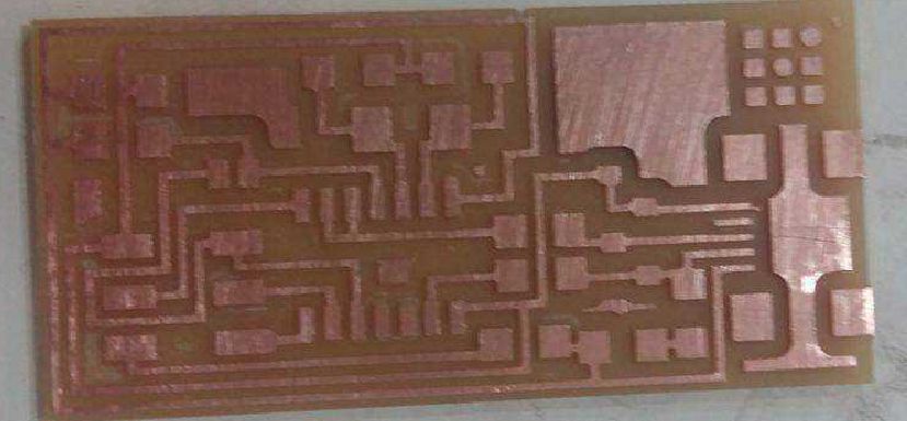
Finally I got my PCB milled completey
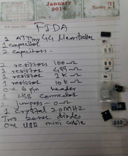
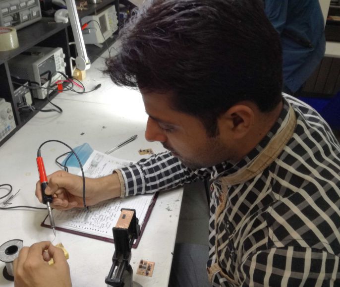
Populating the board
After milling the board now its time to populate the board with the required components, therefore I listed the components on the paper first and started the soldering as shown in images below
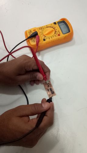
Testing the board with DMM
After soldering the components completely on the board I checked the connections using digital multimeter
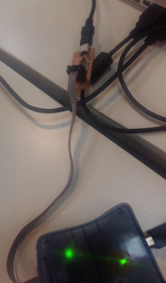
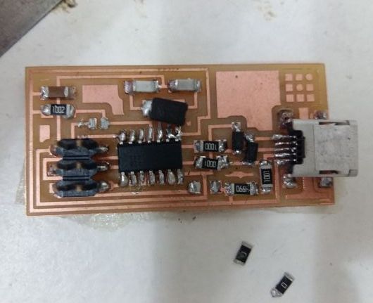
Programming the board
After testing the board by multimeter I went for program the board, for that I took programmer and used mac operating system and with the help of Xavi I performed the several steps to program the board, these steps are elaborated in this tutorial. In the following picture the programmer is showing the green light that means the board connections are ok and it is getting power.
Programming steps
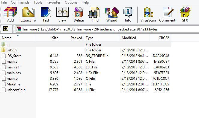
1. Downloading the FAB-ISP firmware
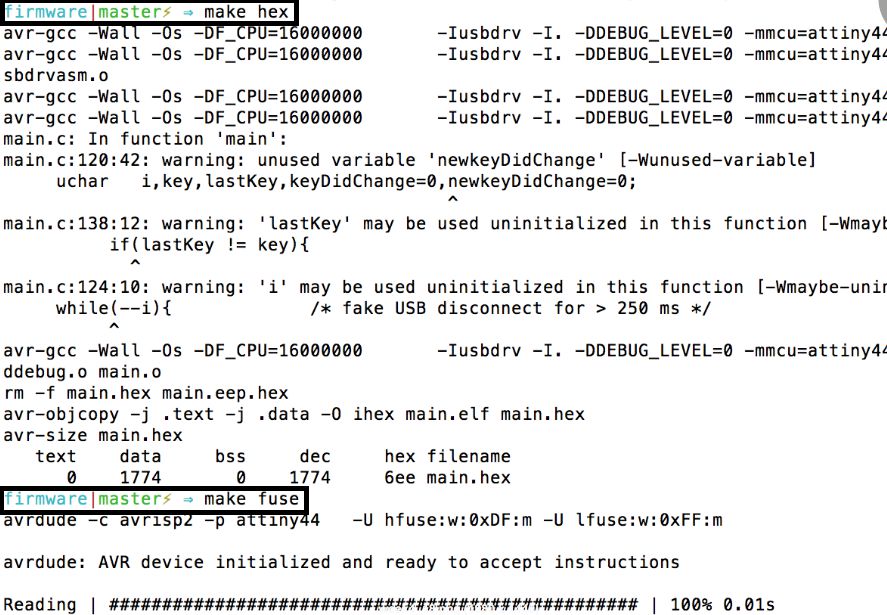
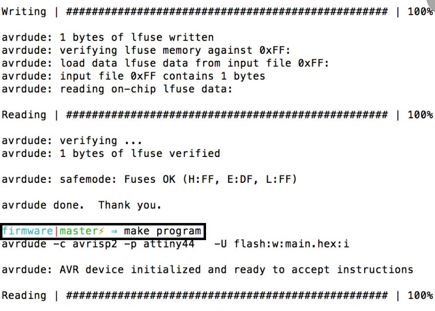
2. Compilation of the firmware
3. Making Hex
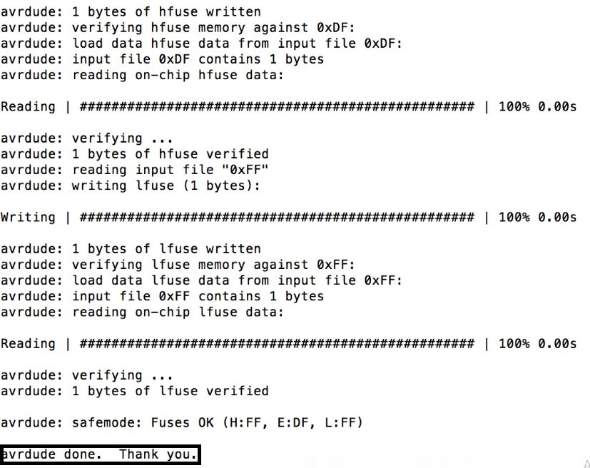
4. Making Fuse
5. Programming the board to become an ISP
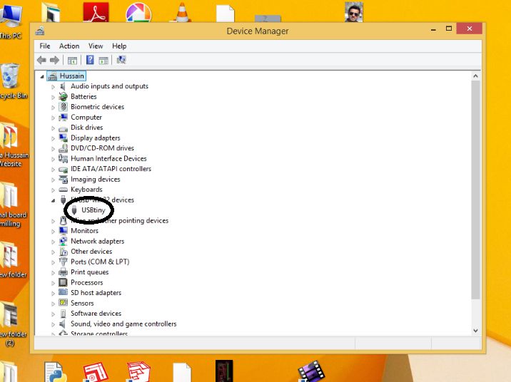
6. Recogninition of the device by computer after succeful programming the board

7. Removing zero ohm resistors as board gets successfully programmed
8. Finally plugging the programmer into computer to see the detection of the external usb device
Download some useful files here