Computer-Controlled Cutting
This week is all about laser cutting and Vinyle cutting and in this week we have perform the assigned tasks individually and in group as well
Task assigned
Group assignment
- Make lasercutter test part(s), varying cutting settings and slot dimensions
Individual assignment
- Cut something on the vinylcutter
- Design, make and document a parametric press-fit construction kit that accounts for the laser cutter and can be assembled in multiple ways
Learning Outcomes
laser Cutting
- Demonstrate and describe parametric 2D modelling processes.
- Identify and explain processes involved in using the laser cutter.
- Develop, evaluate and construct the final prototype
Vinyl Cutting
- Explained how you drew the files.
- Shown how you made your vinyle project.
- Included your design files and photos of your finished project
Group assignment
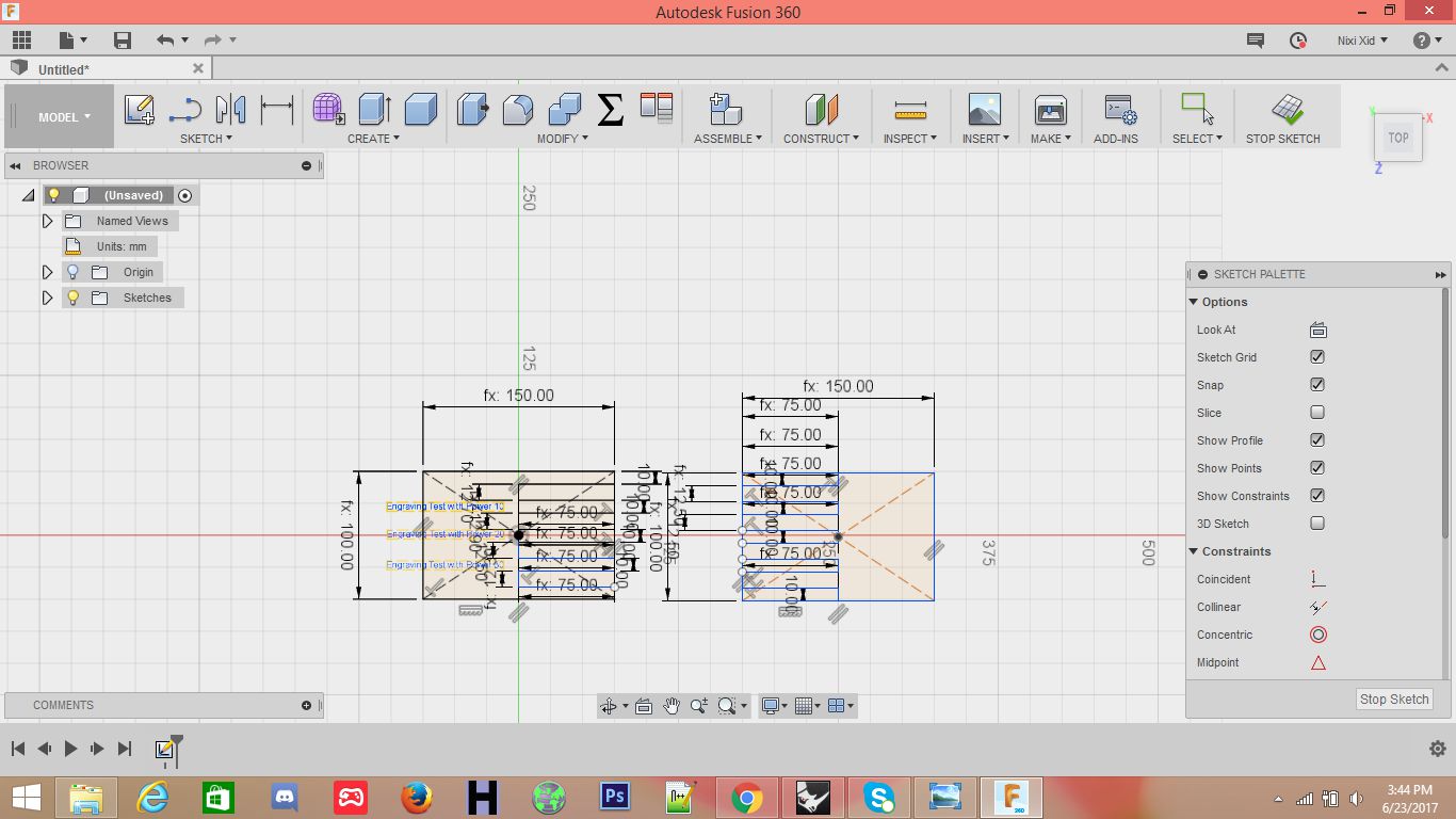
This was our first interaction with the laser cutting machine. We were very delight to know how useful this machine is in a variety of differnt ways. The object of this group assignment was to study the tolerence levels of the machine and to experiment with differnt values of laser power and speeds. For this assignment we made a basic pattern of rectangles. The parameteric design was prepared in Fusion 360 and then imported to Rhino in .igs format.
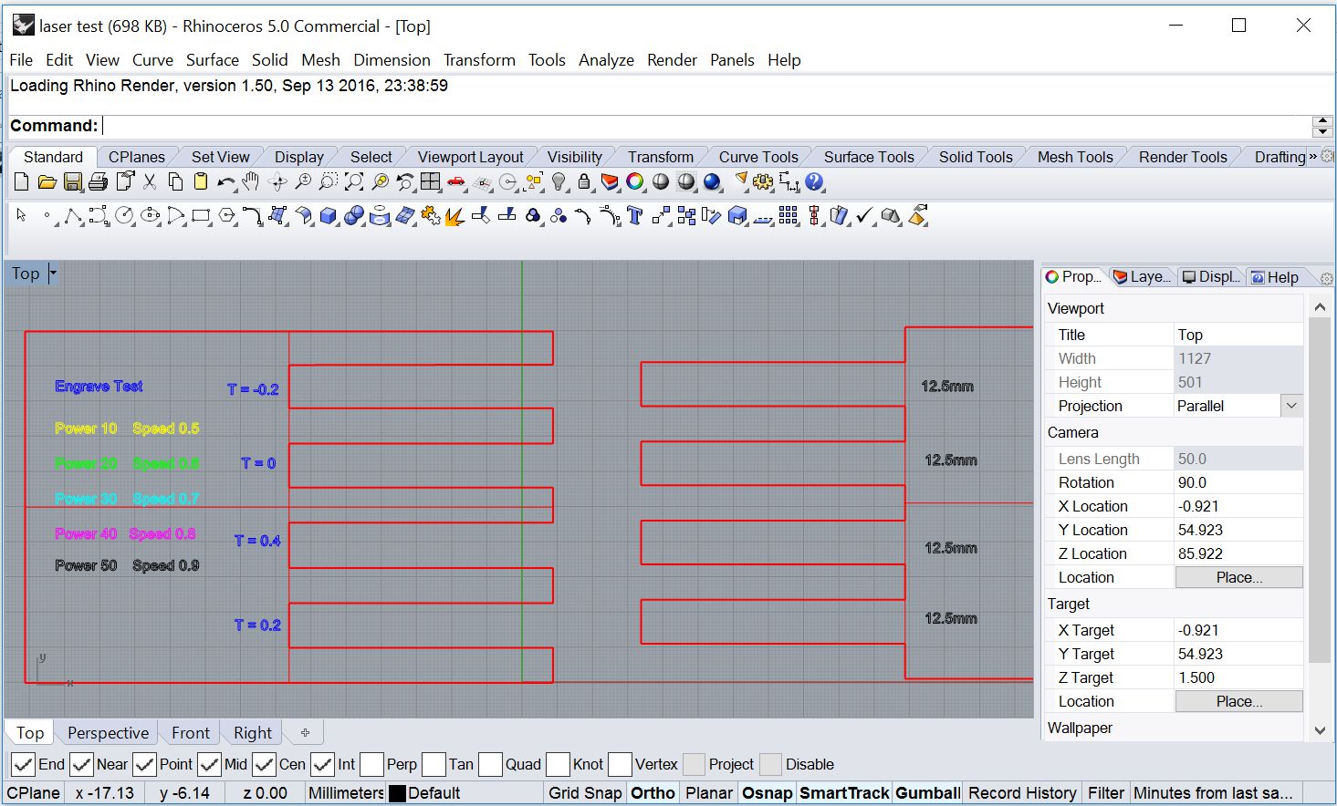
The file was imported is rhino and processed for laser cutting job.
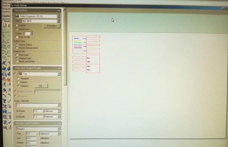
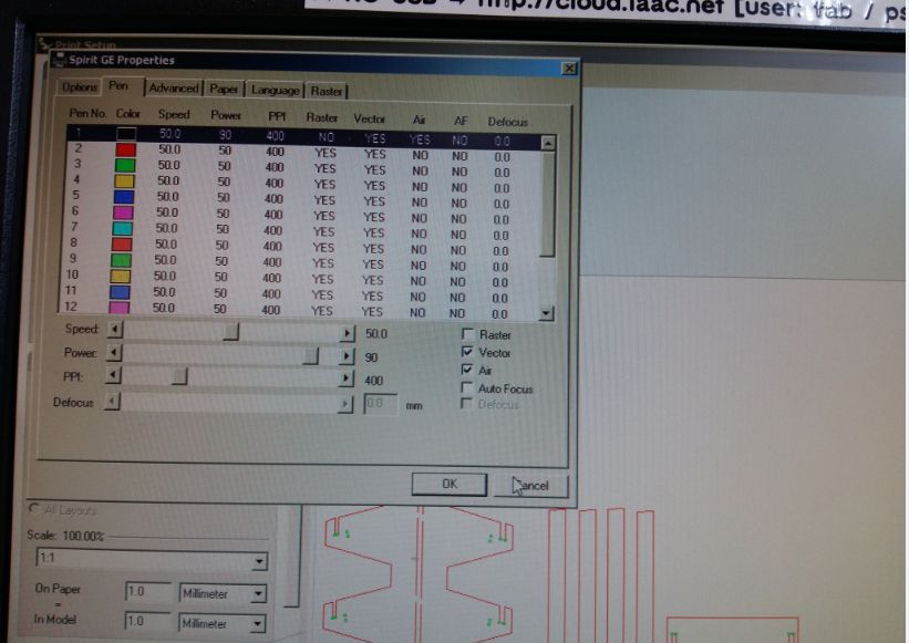
The job is sent to printer by simply clicking print icon. The print area and other properties can be configured using the following window.
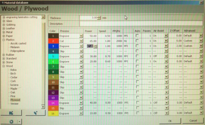
different objects with different printing parameters can be combined in a single job the of can be configure by placing the objects on different layers and assigning different laser power and speeds to each layer. The menu used for this configuration is illustrated below
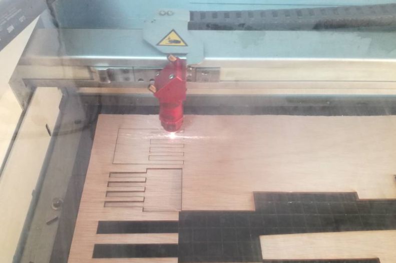
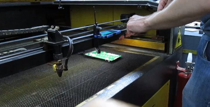
We started the print job by placing the stock on the print bed and setting the stock dimension in the Rhino Print options. Caliberation of laser z-axis must be performed with the help of metallic stub. After double checking everything print command was sent to the printer and it beamed away swiftly.
The Results
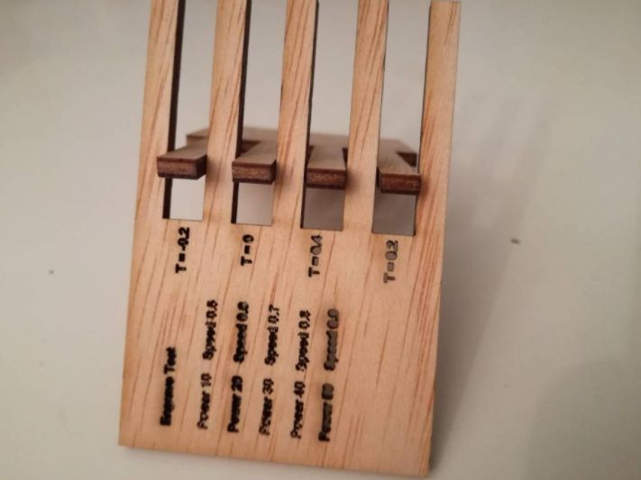
Following tolerances were considered -0.2mm, 0mm, 0.2mm and 0.4mm. The laser power cutting is set at 70. The results are illustrated below
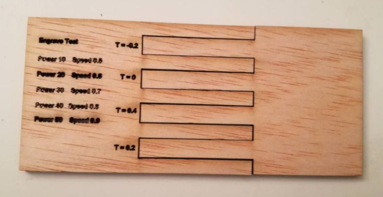
Since the tolerances are in sub millimeter scale the results are not prominent. However objects with lower tolerance would not fit tightly.
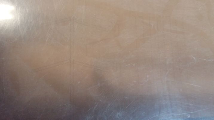
For engraving we tried different laser power and speeds. The results of engraving process are presented below
From our experience we come to conclude that although laser cutting is an effective way of cutting numerous items including paper, card-board, accrylic and plastics. However the laser power and speeds must be carefully choosen to avoid material melting or catching fire.
Individual assignment
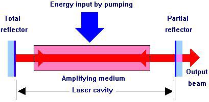
Laser: The term LASER originated as an acronym for "Light Amplification by Stimulated Emission of Radiation". More over a laser is a device that emits light through a process of optical amplification based on the stimulated emission of electromagnetic radiations.
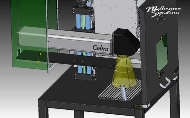
As for as laser cutting technology is concerned it is basically a matter of cutting materials based on computer controlled parametres using high powered beam of light. This technology actually comes into two formats i.e GANTRY, in which the position of laser is perpendicular to the material to be cut and in this machine physically directs the beam over the suface of th material and in contrast we have GALVANOMETER SYSTEMS, that use mirrored angles to reposition the laser beam and can cut as fast as one huncred feet per minute. Most of the fabrication industries use this system rather than gantry system due to high speed. Gantry is slower as compared to galvanometer system. In our Lab we performed this task using Gantry system in which laser beam is perpendicular to surface of the material to be cut.
GANTRY system
GALVANOMETER system
The mechanism of laser cutting technology is to use stimulation and amplfication techniques to convert electrical energy into high density beam of light.
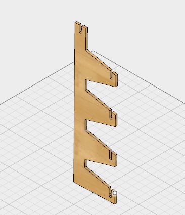
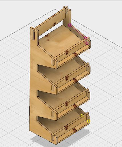
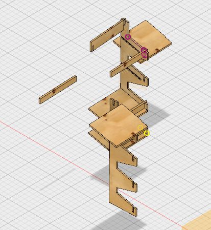
To complete this week's task I started with parametric designing of a model, I used Autodesk Fusion 360 as I found the environment of this software convinient to me. While surffing internet I came across a model which is basically an open shelf to keep domestic consumables at home. this design contains several elements are designed in parametric way and are to be press fitted as shown in following snaps.
Outer side of leg
Inner side of leg (pressfit)
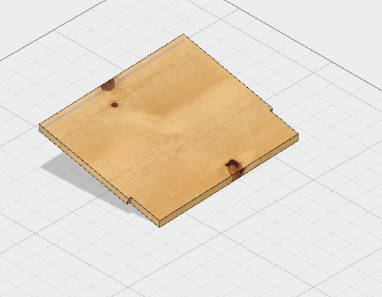
One of the four slabs to be pressfit
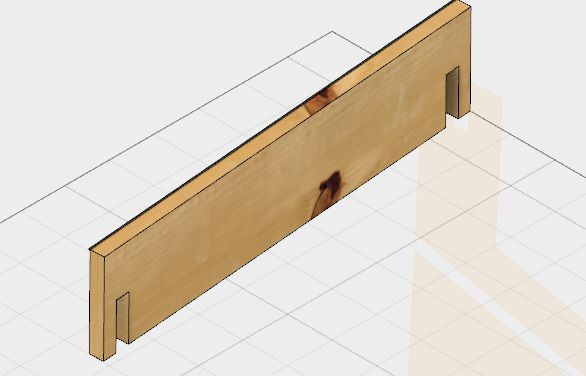
Front support slab to be pressfit
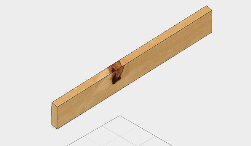
Support at head to be pressfit
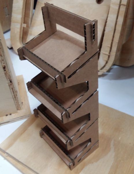
Final Design
All the segments apart from each other
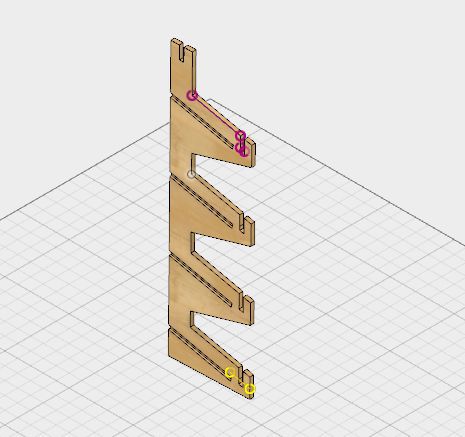
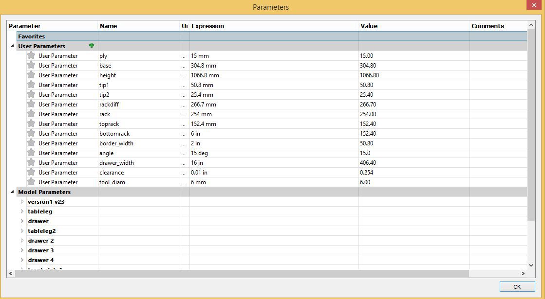
Parametric measurements
Preparing the file to be laser cut
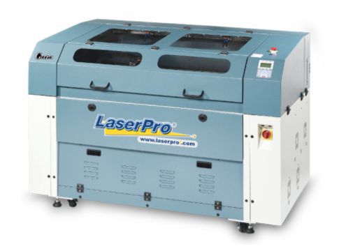
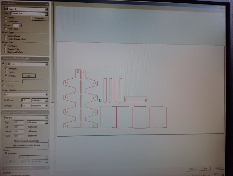
Exporting the file from fusion 360 as iges file and then open it into Rhino and made some changes to prepare the design file to be laser cut. I used LASER pro machine for this task, this laser cutter has 1300 mm by 916 mm of working area and it cuts through 1 inch (25mm) acrylic effortlessly in a single pass with clean edges this machine seemed very user freindly to me
Exporting file to rhino for cutting
Color settings
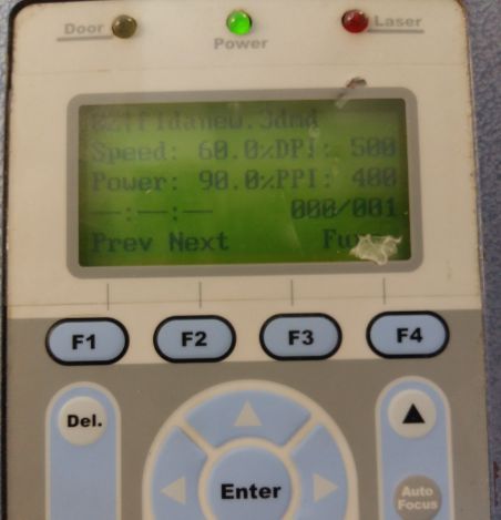
Power and Speed settings
The Power setting determines exactly that you can control how much power will be applied to the laser while printing. The more power the more heat, and the more heat the greater the chance of fire. The speed you choose, determines how fast the laser will travel while cutting. The slower the speeds, the longer the laser sits in each spot, which yields more heat. It also means that the slower the speed, the deeper the cut or engraving will be.
So after performing group assignment I supposed the following values of power and speed if the material I m using is card board. these values are sufficient to prenvent cutted object safe from fire or other hazardeous conditions.
Cutting process
I used card board material I found in the lab which fits the dimensions of my design. Befor starting make sure your presence through out the process as Acrylic, Wood, Paper, Plastic, Laptops, and a whole host of other things are flammable, so please don't walk away mid cut, you may come back to more then you hoped for. As Cardboard is a generic term for a heavy-duty paper of various strengths, ranging from a simple arrangement of a single thick sheet of paper to complex configurations featuring multiple corrugated and uncorrugated layers.
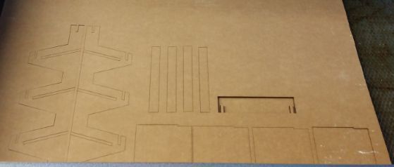
Opening the machine after complete laser cutting
Assemblling the laser cut segments (press fitting where needed)
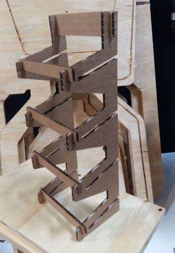
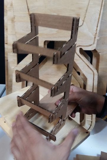
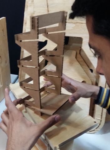
Front view of the final model
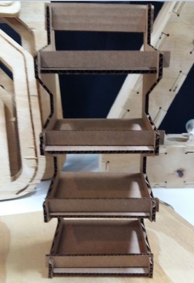
Rare view of the final model
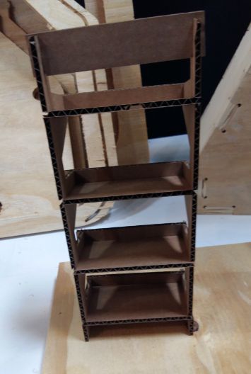
Hero shot of the Model
As for this asignment requirement I came with above results but design is parametric so we can extend the geometry of the ddesign to large scale to obtain something big as I did in the week 7 computer controlled machining week.
Vinyl Cutting
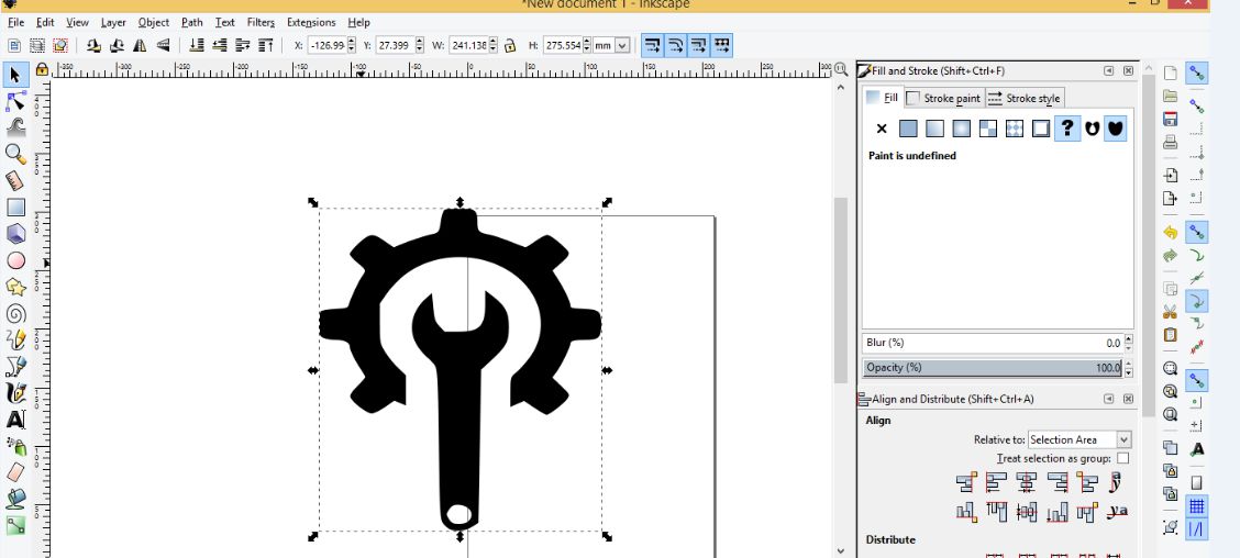
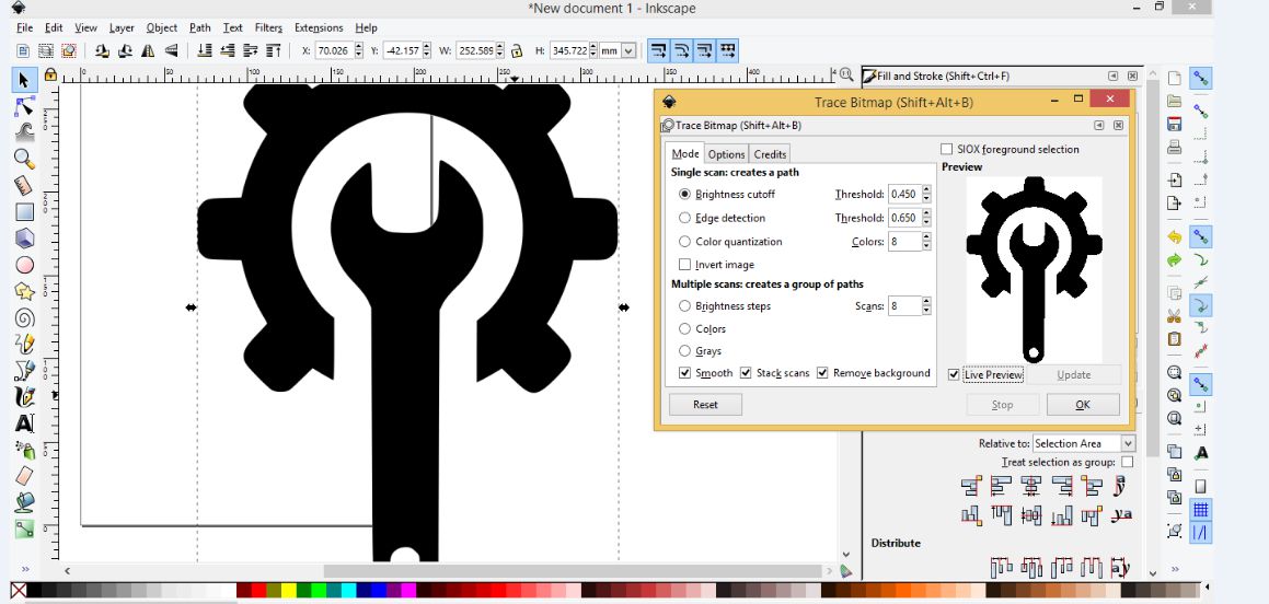
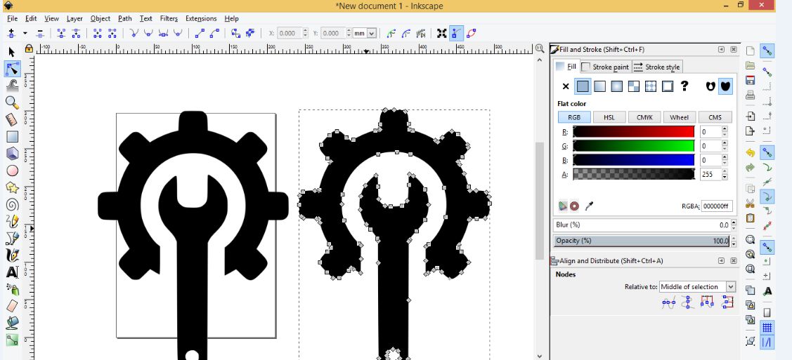
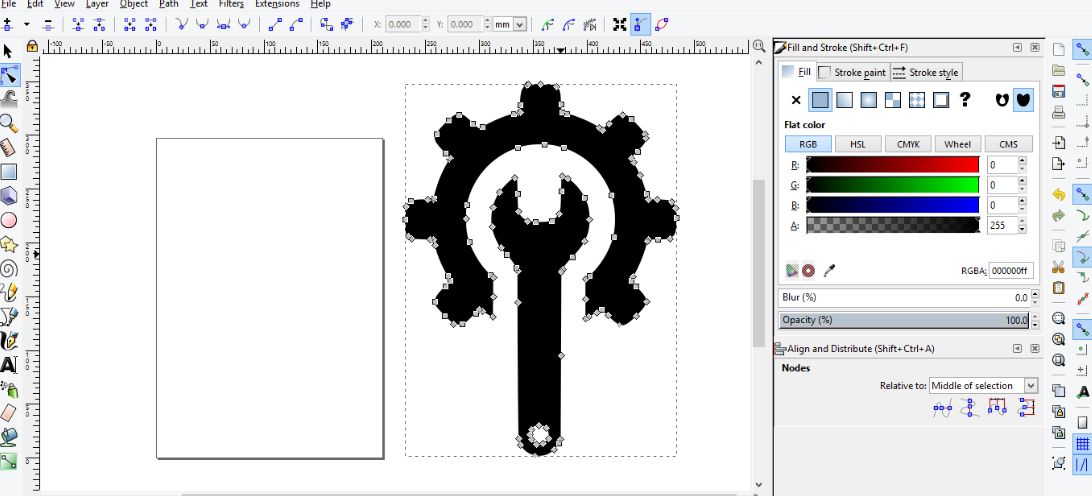
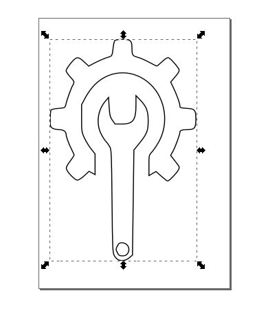
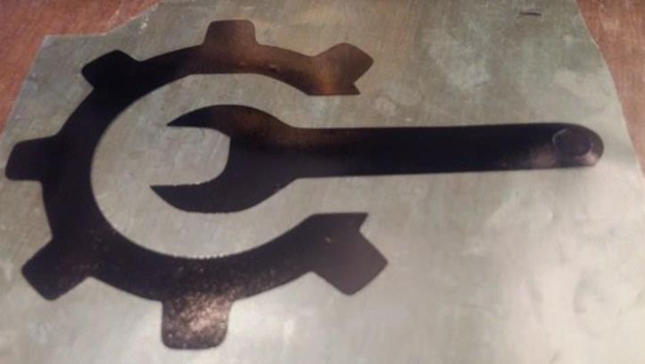
I started searching the image related to my final project and I got a wrench gear image I import that image in Inkscape used some keys and functions like "Shift+ctrl+F", tracing the bit map for the picture imported to a certian settings and finally with some fine tuning filling the unfilled areas and set the stroke in order to prepare the image for cutting.
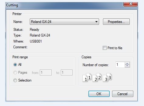
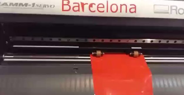
After that I export my file in Cutstudio software which is basically providing an interface of the machine Roland GX-24 to set parameters of the sheet on which we are going to perform the vinyl cutting for specific design.
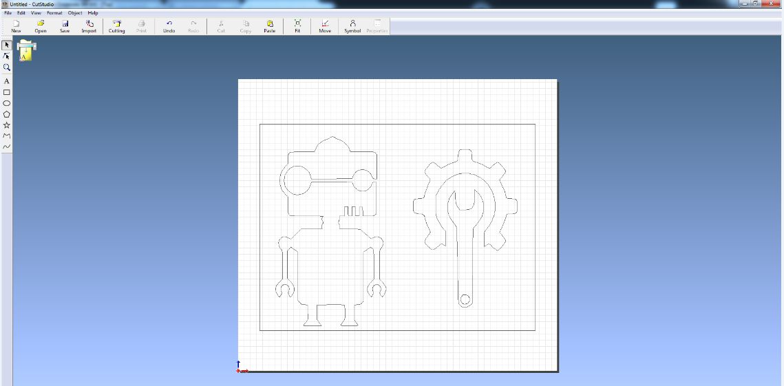
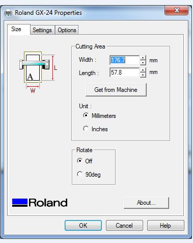
Now setting cutting parameters to the specific dimension obtained automatically from machine to interface software and after settings press print and observe the cutting on the sheet inserted in the machine
Getting dimensions from machine
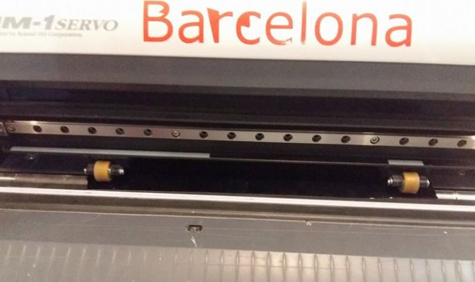
Roland GX-24 started cutting
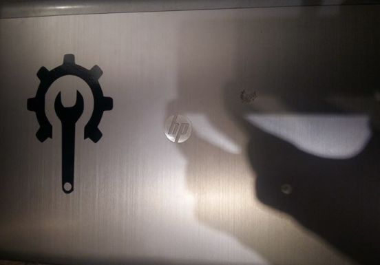
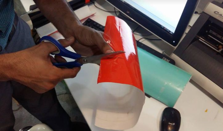
Finally I got my output sticker and I placed that on top surface of my laptop process is shown snaps below.
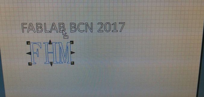
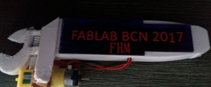
I also printed some text using vinyl cutting and paste that text on the ecrylic sheet that I used in my final project product as shown below.
Download useful files here