Applications and Implications
Assignment
This assignment is about proposing a final project that integrates the range of units covered.
Learning outcomes
Scope of Project
Development of project plan
Answering the questions
What it will do?
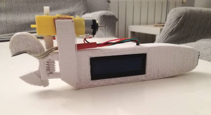
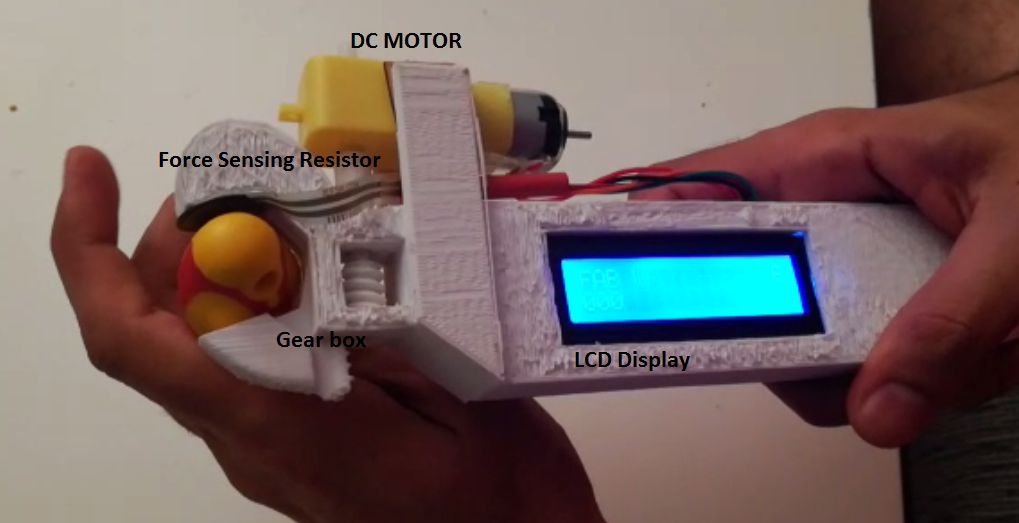
As for my final project I want to develop an adjustable wrench that is mostly used for opening and closing the nuts and bolts, usually this device is available in mechanical workshops and repairing shops. As this wrench is featured with LCD to display the the range of force to be applied on the nut to be opened or closed, a dc motor that is used to revolve the gear part and a force sensor resistor which is integrated on the tip of fixed jaw of the wrench. Basically this force sensor is an input for the process, as this is force value reaches up to certain limit motor starts and revolve the gear for certaion time of period so that jaws can be opened upto certain space for holding the nut in between. Next we apply the force by holding the nut and that value force is conveyed to micro controller and resulting the motor revoving in opposite direction to hold the nut in this way when threshold value of the force is acheived the motor stops and nut becomes enough tightened between the jaws to be opened or close.
Who's done what beforehand?
Before this only lcd display was there to show the measurements and wrench gear was being adjusted mannually here in my project I have also added dc motor to revolve the gear which is programmed as the variance in force value of sensor attached to the fixed jaw. As this product is so sofisticated by the addition of force sensor and DC motor. the revolving of gear using dc motor is the value addition to this project
What materials and components will be required?
1. LCD display
2. Force sensing resistor
3. DC Motor
4. 9v Battery
5. 3D printed casing including laser cut ecrylic sheet
6. 3D printed gear part
7. Microcontroller based circuit
8. Miscellaneous resistors and capacitors as per requirement of circuit
9. A switch button
Where will they come from?
1. LCD display (from fab lab Bcn)
2. Force sensing resistor (from fab lab BCN)
3. DC Motor (from fab lab BCN)
4. 9v Battery (from fab lab BCN)
5. 3D printed casing including laser cut ecrylic sheet (from fab lab BCN)
6. 3D printed gear part (from fab lab BCN)
7. Microcontroller based circuit (from fab lab BCN)
8. Miscellaneous resistors and capacitors as per requirement of circuit(from fab lab BCN)
9. A switch button (from diotronix Barcelona)
How much will it cost?
1. LCD display (1.5 euro click here for the link)
2. Force sensing resistor (8.32 euro click here for the link)
3. DC Motor (4.99 euro click here for the link)
4. 9v Battery (1.5 euro click here for the link)
5. 3D printed casing including laser cut ecrylic sheet (approximately 2 euro)
6. 3D printed gear part (approximately 0.5 euro)
7. Microcontroller based circuit (1 euro, www.digikey.es)
8. Miscellaneous resistors and capacitors as per requirement of circuit(approximately 3 euro, www.digikey.es )
9. A switch button (0.75 euro from diotronix Barcelona)
Total cost = 24 euros lumpsum
What parts and systems will be made?
1. Pcb board containing Atttiny 44 controller for controlling the components interfaced
2. 3D printing/ laser cutting / vinyl cutting
3. Gear design with motor interface
What processes will be used and what tasks need to be completed
1. PCB design in eagle
- input and output devices
2. Electronics production (fab modules->milling->soldering->debugging)
3. 3D design using rhinoceros (casing of wrench design)
4. 3D printing (printing wrench casing)
5. Laser cutting (ecrylick sheet)
6. Vinyl cutting (text over ecrylic sheet)
7. Programming using arduino IDE
What questions need to be answered
1. How to calculate force required for specific nut
2. How to control motor with variance in the resistance of the sensor at the input.
3. How can I make it more stroger and fancy too
4. Will it be reliable for large scale forces
5. How can make gear part with in the same casing inside.
6. How can I come to know that when I have to change the battery
7. How can I took my design for different resistive sensors with different ratings
What is schedule
1. Week#01 Electronics design soldering and testing the main board
2. Week#02 Designing 3D printing model and getting it printted
3. Week#03 Most challenging week (ooohh) getting the gear part printed and functional
4. Week#04 Laser cutting, Vinyl cutting and assembling all the parts to form final product.
How will it be evaluated?
1. Displaying three different values of force sensor on LCD i.e opening, catching and tightening
2. Casing is made of 3D printing material not the metalic one.
3. Portable.
For more details about final project click here