
Assignment
- Design and build a wired &/or wireless network connecting at least two processors
0. Idea.
- For this assignment I decided to connect E-Paper display with my laptop over wifi using ESP8266. This is also one of the requirement of my final project as well.
- Then I will connect resistive touch with my phone using esp8266.
- First I will try to connect esp8266 with the a microcontroller board which support 3.3V logic levels, as we know that esp8266 supports only 3.3V levels for Data and power.
- So the first thing I have to do is to fabricate a microcontroller board and then interface it with esp8266.
- The next thing is to interface E-Paper display with that microcontroller board.
- And the last thing is to write a python script which send a message to E-Paper display over wifi, so that I can establish wifi connection between my system (E-Paper, esp8266 and microcontroller) and my computer.
1. Microcontroller Board.
- In assignment 10 I have already fabricated a board based on ATMEGA32u4 but that operates on 5V and getting that 5V from USB and supply to all other components on board. So, I have to add a 3.3V regulator on the board to interface ESP8266 or I use a level converter circuit. I decided to make a board which works on 3.3V because this voltage level is good to use for portable device and this wifi based system will going to be the part of my final project which is a portable device.
- Following image shows the microcontroller board that I have designed to fabricate, but I made a mistake here, that is i used a 3.3v regulator with 100mA rating which was not enough for wifi. Board can we seen in the image given below.

- I realize this after fabricating the board. Then I milled another PCB for 3.3V 1A regulator as shown below.

- Now using the regulator above I can power my microcontroller board and esp8266 as well.
- List of components used for board.

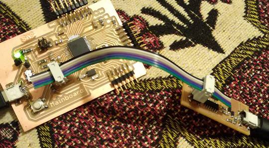
- After soldring here is how it looks like.

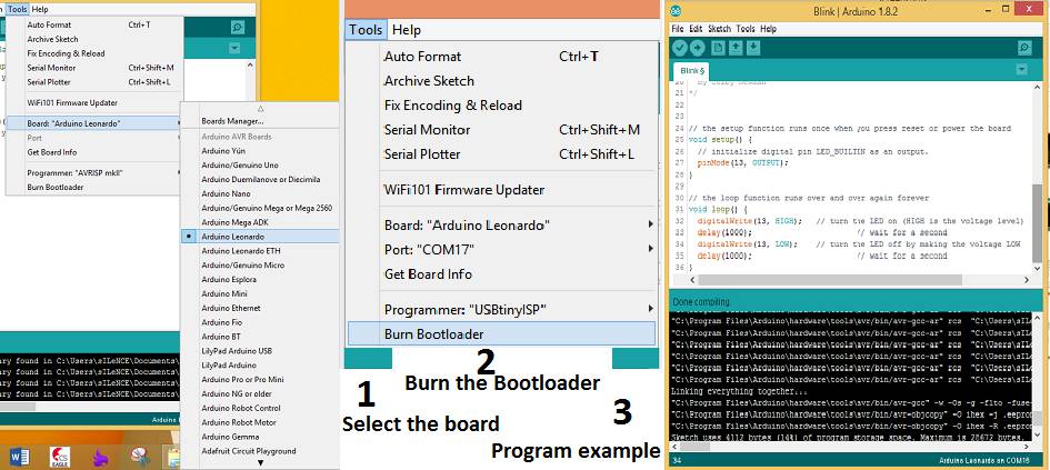
- Burning the bootloader using Arduino IDE and my fabISP. I am buring the boot loader of Leonardo.
- Now my microcontroller board is ready to work on 3.3V. :)
2. Interfacing ESP8266.
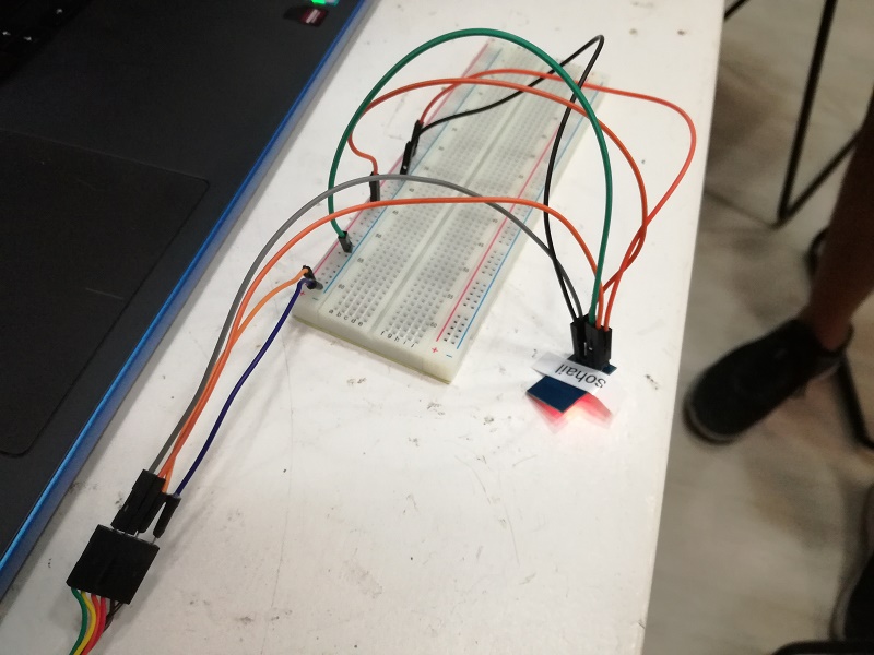
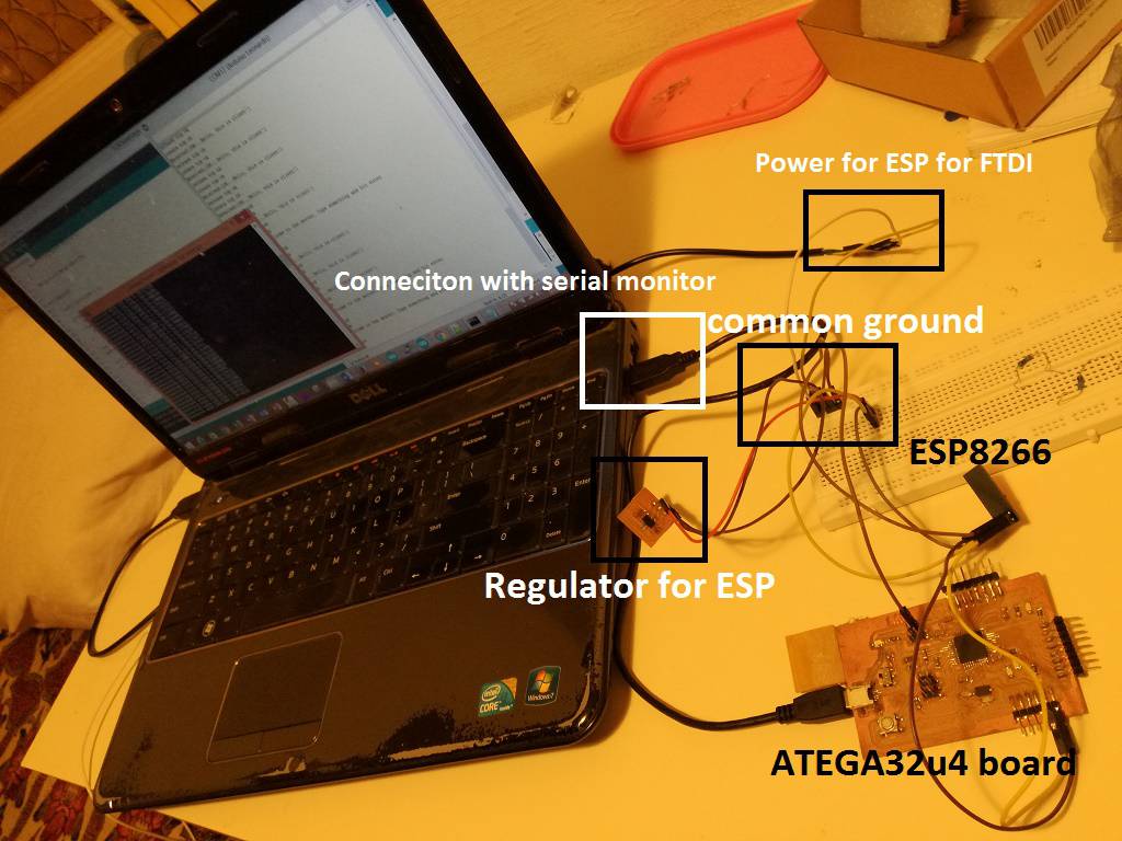
- it was my first time to work with ESP8266 I thought to interfacing ESP8266 with with Arduino MEGA first and try some AT commands
- This is how the setup look likes.

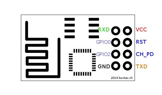
- Following images shows the pinout of esp8266.
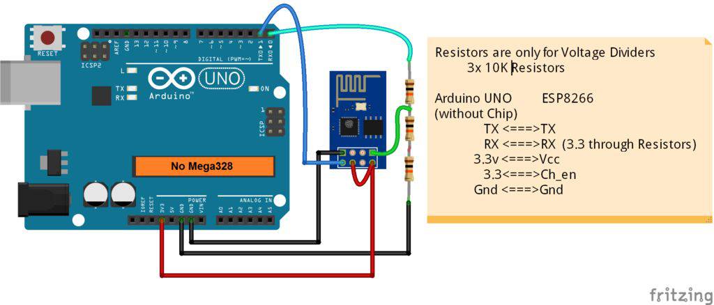
- I followed this tutorail. http://www.instructables.com/id/noobs-guide-to-ESP8266-with-Arduino-Mega-2560-or-U/ and wired as shown in the image below.
- Above image shows the connection of esp8266 with Arduino UNO but we can do the same connection with Arduino MEGA as well.
- To talk with esp8266 I used Multiserial example of Arduino. And then I tired few AT commands on ESP8266, following images shows the response.

- Now I will interface esp8266 with the board I have designed. see the picture below for the connection.
- First I tried to use some AT command to check the connection and then made the connection with AP using AT commands and It works, following gif file is showing the response
- To program esp8266, i found this library really usefull. https://github.com/itead/ITEADLIB_Arduino_WeeESP8266
- After working with lots of library for esp8266 I found the library discussed above very helpfull and I use the tcp client example of the library. The following video shows the complete setup.
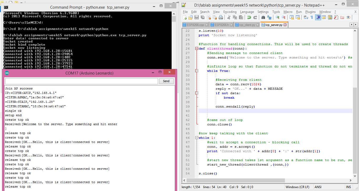
- I found this TCP server/client python script, after putting IP and port address I was able to use it. I am using it in to send and receive data from esp8266. The script is linked at the end of this page.
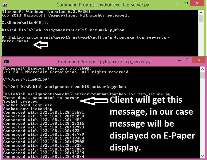
- The following image shows who to run the script and wait for the client to connect.
- When we run the script it will ask for the data to send. as shown in the image given below.
- Here are the few snapshots of communication.
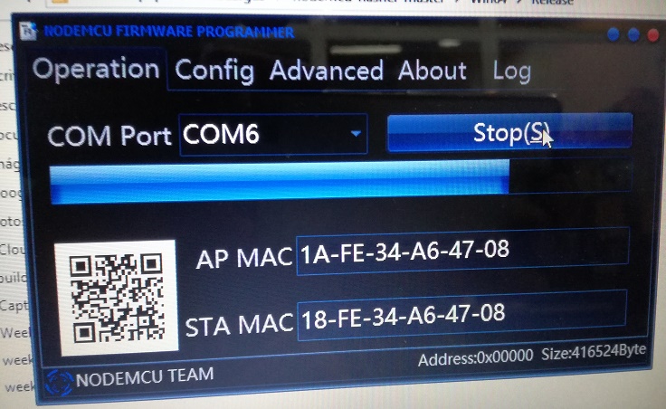
5.1 Flash ESP8266 and configure it as TCP server.
Download the flash tool from this (https://github.com/nodemcu/nodemcu-flasher) link. and followed the instruction given on that page.
Here are few pictures of this process
We can also find the wiring circuit diagram to flash esp8266 from this (http://randomnerdtutorials.com/flashing-nodemcu-firmware-on-the-esp8266-using-windows/) link.
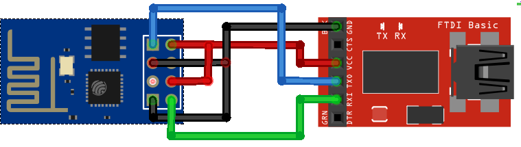
If every thing goes well you will see the some thing like image given below.
Now its turn to add ESP8266 library into arduino IDE. I can find the library from here (https://github.com/esp8266/Arduino). We can also find the instructions on this page. It is really usefull. it help me a lot.
Now after adding the library go the arduino and select the following setting to program ESP8266.

And Now I have written the following program in Arduino IDE to configure ESP8266 as TCP server.
#include <ESP8266WiFi.h>
const char* ssid = "Mypho";
const char* password = "1234567890";
const int ledPin = 2;
WiFiServer server(1337);
void printWiFiStatus();
void setup(void) {
Serial.begin(115200);
WiFi.begin(ssid, password);
// Configure GPIO2 as OUTPUT.
pinMode(ledPin, OUTPUT);
// Start TCP server.
server.begin();
}
void loop(void) {
// Check if module is still connected to WiFi.
if (WiFi.status() != WL_CONNECTED) {
while (WiFi.status() != WL_CONNECTED) {
delay(500);
}
// Print the new IP to Serial.
printWiFiStatus();
}
WiFiClient client = server.available();
if (client) {
Serial.println("Client connected.");
while (client.connected()) {
if (client.available()) {
char command = client.read();
Serial.print(command);
}
if (Serial.available() > 0) {
char incomingByte = Serial.read();
client.print(incomingByte);
}
}
Serial.println("Client disconnected.");
client.stop();
}
}
void printWiFiStatus() {
Serial.println("");
Serial.print("Connected to ");
Serial.println(ssid);
Serial.print("IP address: ");
Serial.println(WiFi.localIP());
}
And thats all, we are done with flashing esp8266 and configuring it as tcp server.
I have already interfaced Resistive touch with Atmega32u4 in my input assignment, i will use the same setup as in input assignment and send the data from resistive touch to phone using esp8266. On wifi side every thing remains same as dicussed above this time I am sending the data instead of receiving.
3. TCP Server Pythone script.
4. Connecting all together.
In assignment 10 I already explained the process to interface the E-paper display, so I am using that same program and trying to show the data coming from computer.
Now after fabricating the microcontroller board, interfacing the esp8266, running the python script and interfacing the E-paper paper display finally we are ready to see the things working all together.
The following video shows the process and the results.
5. Resistive touch interface with esp8266 .
In the above section I am using esp8266 with a library based on AT commands, but this time i decided not to use AT commands to talk with esp8266, because such library which are based on AT commands are like overhead on microcontroller, Why not to configure esp8266 it self as TCP server using its own flash which just send and receive data to microcontroller. To do that first we nned to flash esp8266 with the help of this tutorail to burn modemcu firmware and found the following tutorail very usefull.
Following video will show the results.
This is all for this assignment, still I will work on the arduino program and python script to full the final project requirements.
Download All file of this week Here

This work is licensed under a Creative Commons Attribution-NonCommercial-ShareAlike 4.0 International License
.