10.- Output Devices
Mar 29
Assignments:
-add an output device to a microcontroller board you've designed and program it to do something
LCD
For this week he chose a 16x2 liquid crystal display with the aim of creating a chess clock with a single button and a led.
In my plate pcv put two free pines to put the button in the week of imput
It has been a challenge for arduino programming.
Arduino leonardo
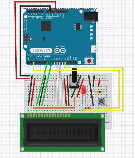
My first step was to mount the protoboard with my arduino leonardo and the lcd. And begin to try simple programs.
Here are some references that have helped me with my first steps
www.prometec.netwww.tested.com
main refence
Code
To be able to use the lcd included the library LiquidCrystal.h that allows to use commands of type: "lcd.setCursor (0, 0); lcd.print (": ");
You must define the pins used with: "LiquidCrystal lcd (7, 8, 9, 10, 11, 12);" And the screen type with: "lcd.begin (16, 2);"
I used the example of arduino "debounce" as a base to be able to change the timer from one player to another so that when the led is on it is the turn of the target and when it is off it is the turn of black.
With this tool I can put a symbol created by me to mark the turn of the player.
Download the files of this section here : DebouncechessClock1.ino
In this first attempt to get the change of player by the button but the timer did not run fluid, Using "millis" lost a few seconds down the road
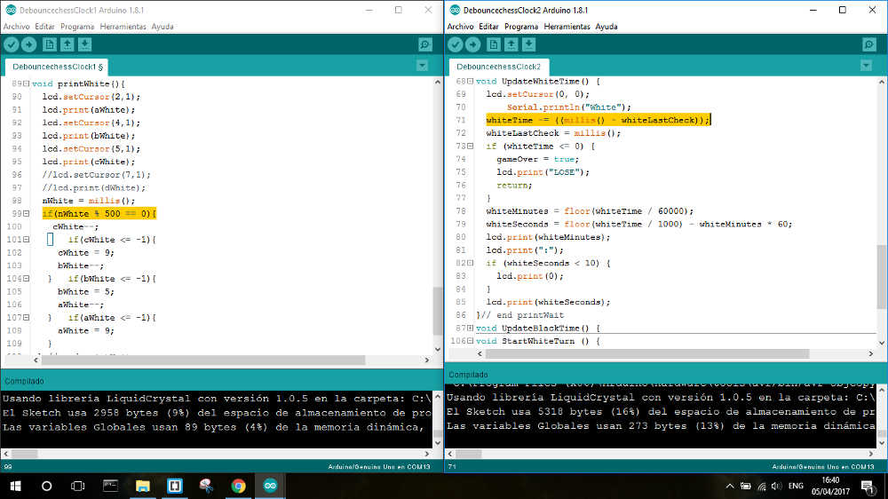
Download the files of this section here : DebouncechessClock2.ino
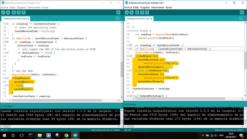
In the second code I have recovered the lost time and the counter goes fluid
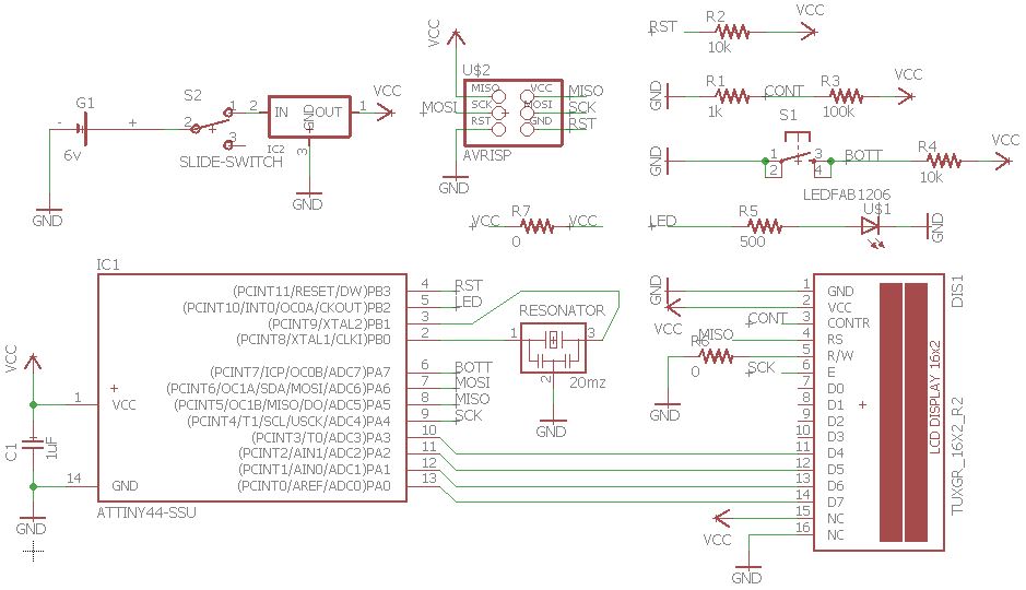
PCB
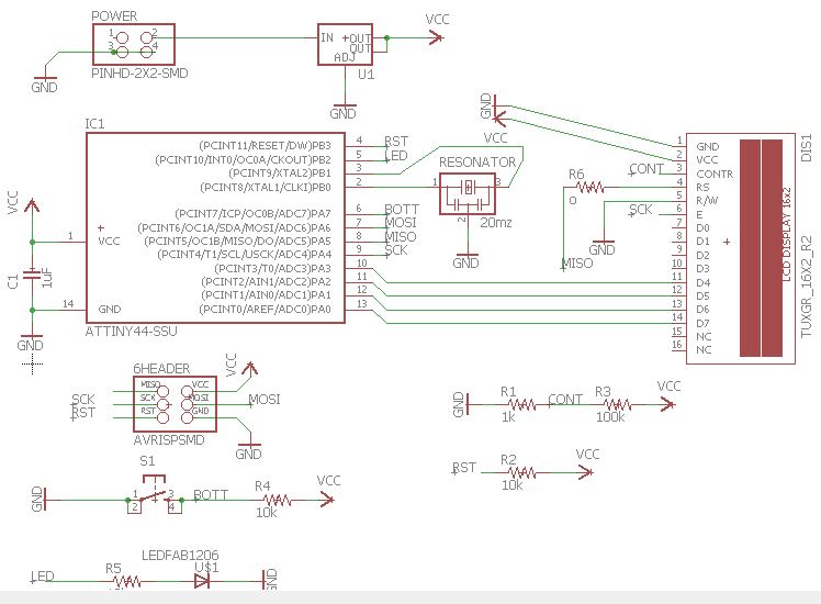
I made the decision to use attiny 84 because it has the necessary memory to store the code along with the library of Liquid Crystal. In addition the screen consumes 7 pins of the microcontroler so it becomes necessary Attiny 84.
This was my first attempt at eagle but later I wanted to make it more integrated and more compact
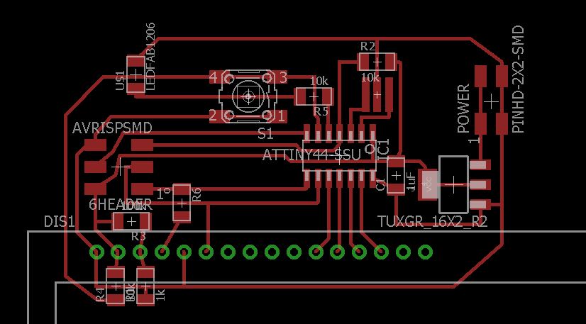
Download the files of this section here : chessClock
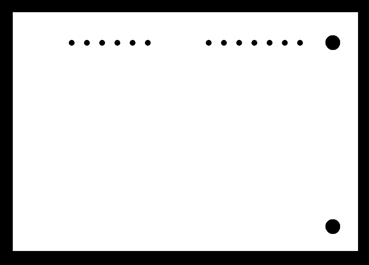
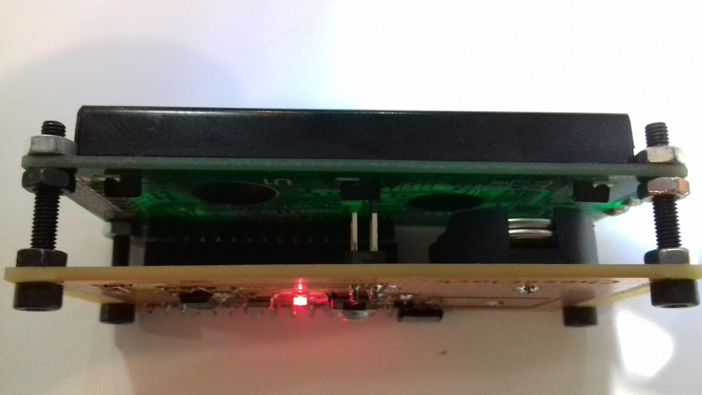
This was my second attempt connecting the screen behind the pcb. My goal was to simulate the touch screen effect by placing the button behind and activating it by pressing the screen and the button against the table. Rearrange the programming pins so that the button is the highest element.
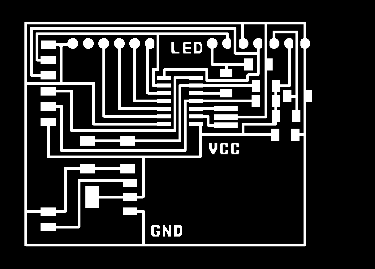
I was not able to load the program and decided to do an improved version
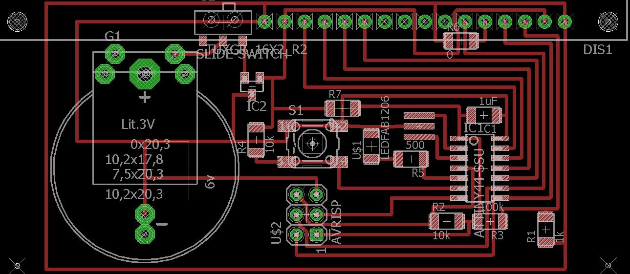
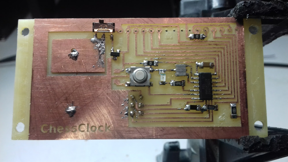
Final PCB
In this PCB I have added button cells and a switch to save battery. I have also reorganized all the components.
The head for the arvisp is connected from the reverse to be programmed from below
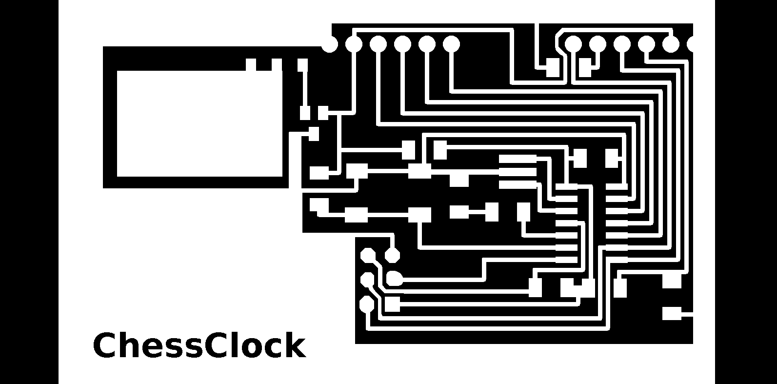
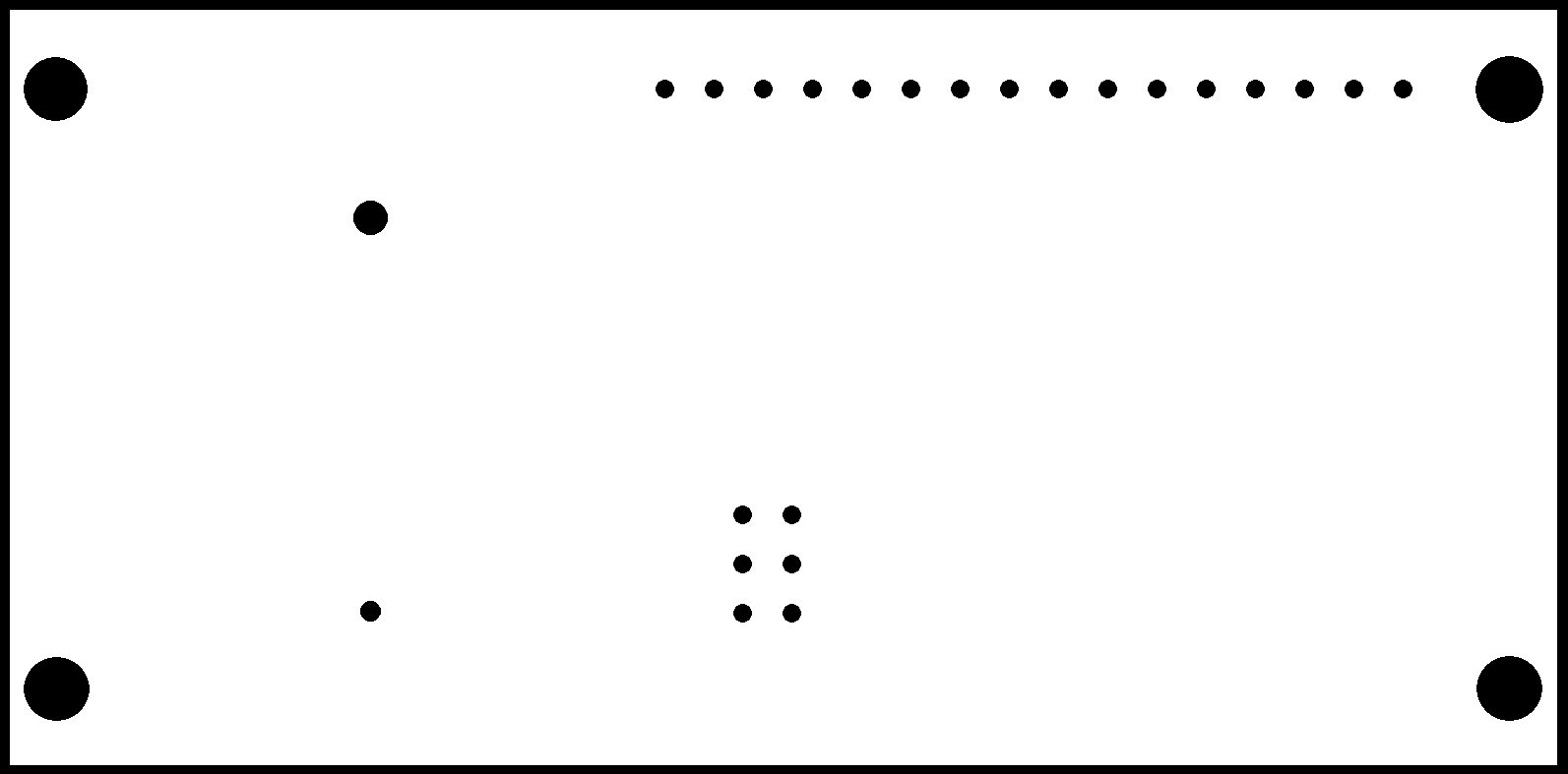
Download the files of this section here : aegle chessClock
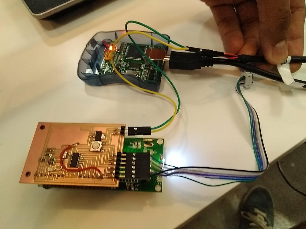
Results
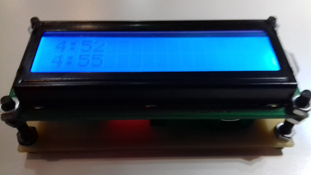
Download the files of this section here : DebouncechessClock3.ino
Use the same program but with the pins corresponding to attiny 84
