Assignment
-
Make an in-circuit programmer by milling the PCB
-
Optionally trying other processes.
Make an in-circuit programmer by milling the PCB
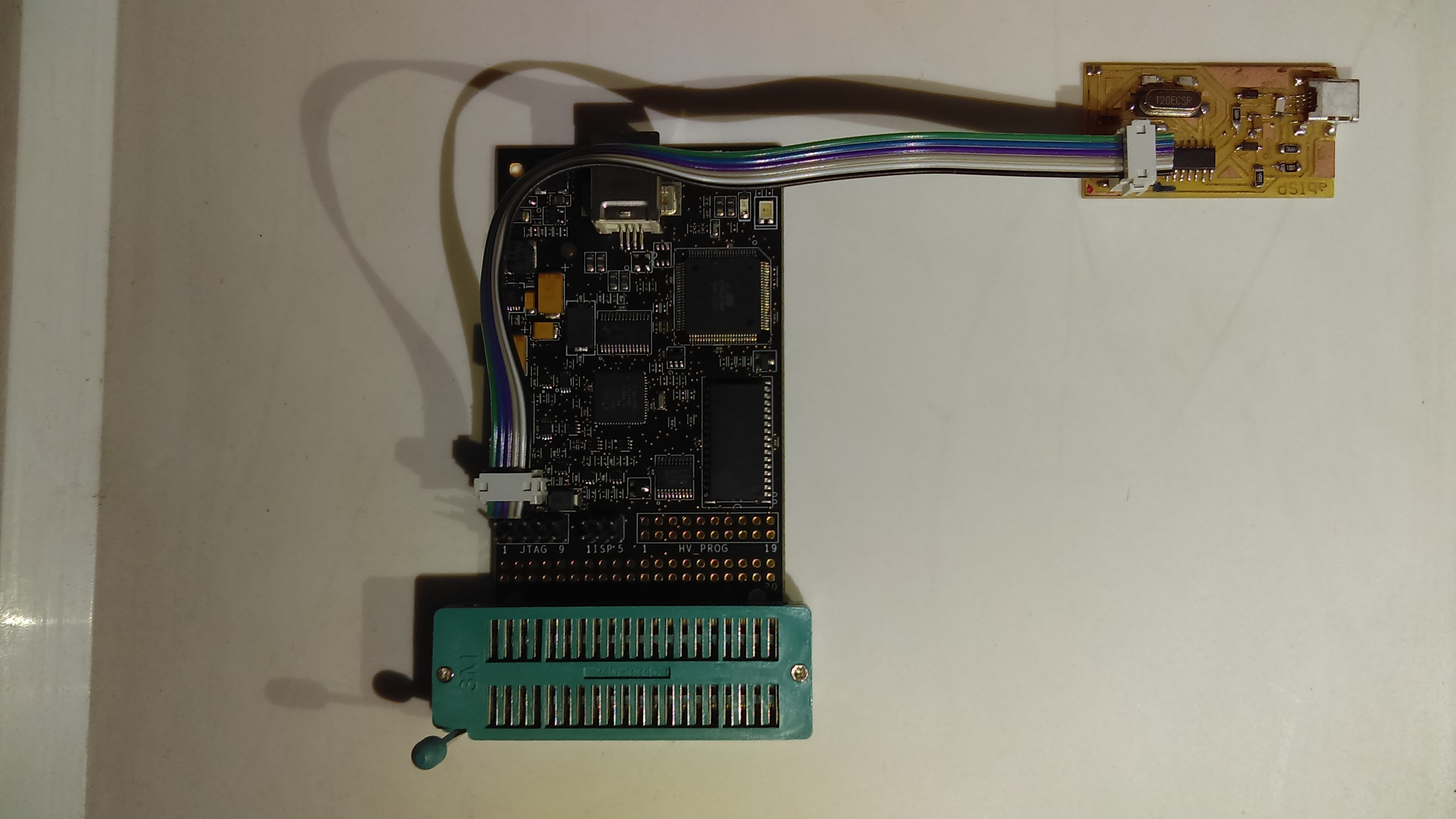
This week work to make an own FABISP, this board is very useful. When creating any new board with any microcontroller (avr family), normally you need load some program inside, the fabisp is a board to make this be a possibility. Only you need to connect the fabsip in your computer and run the specific command to program the new board.
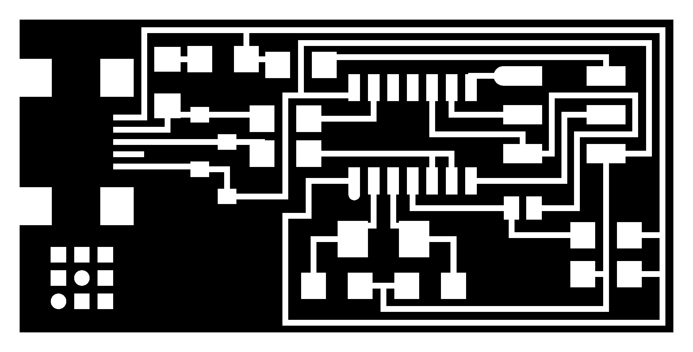
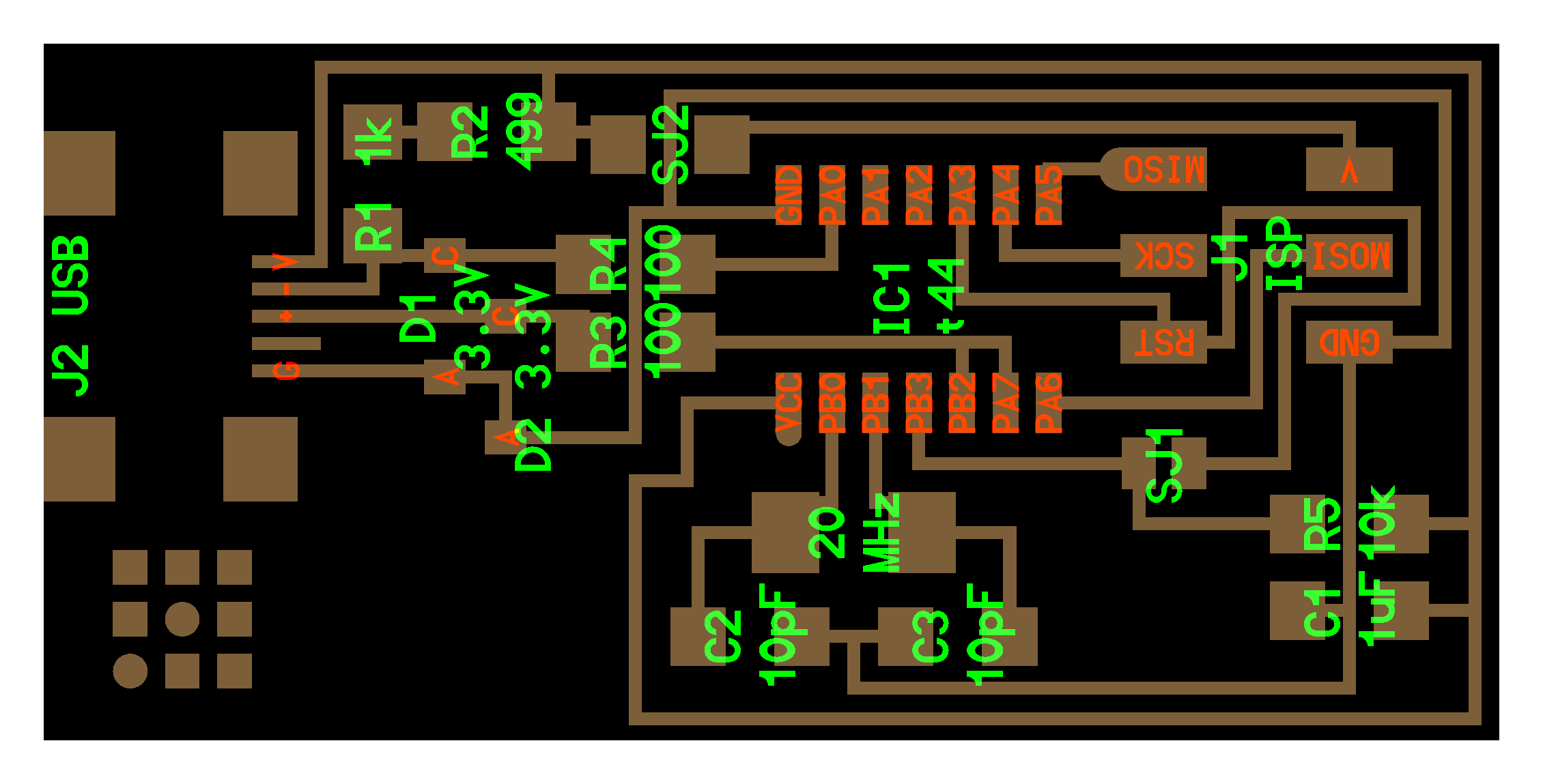
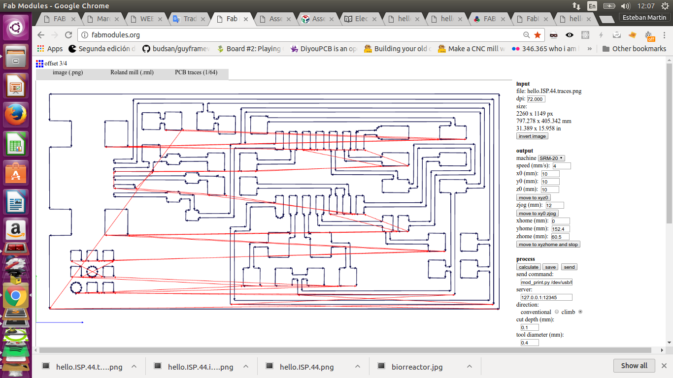
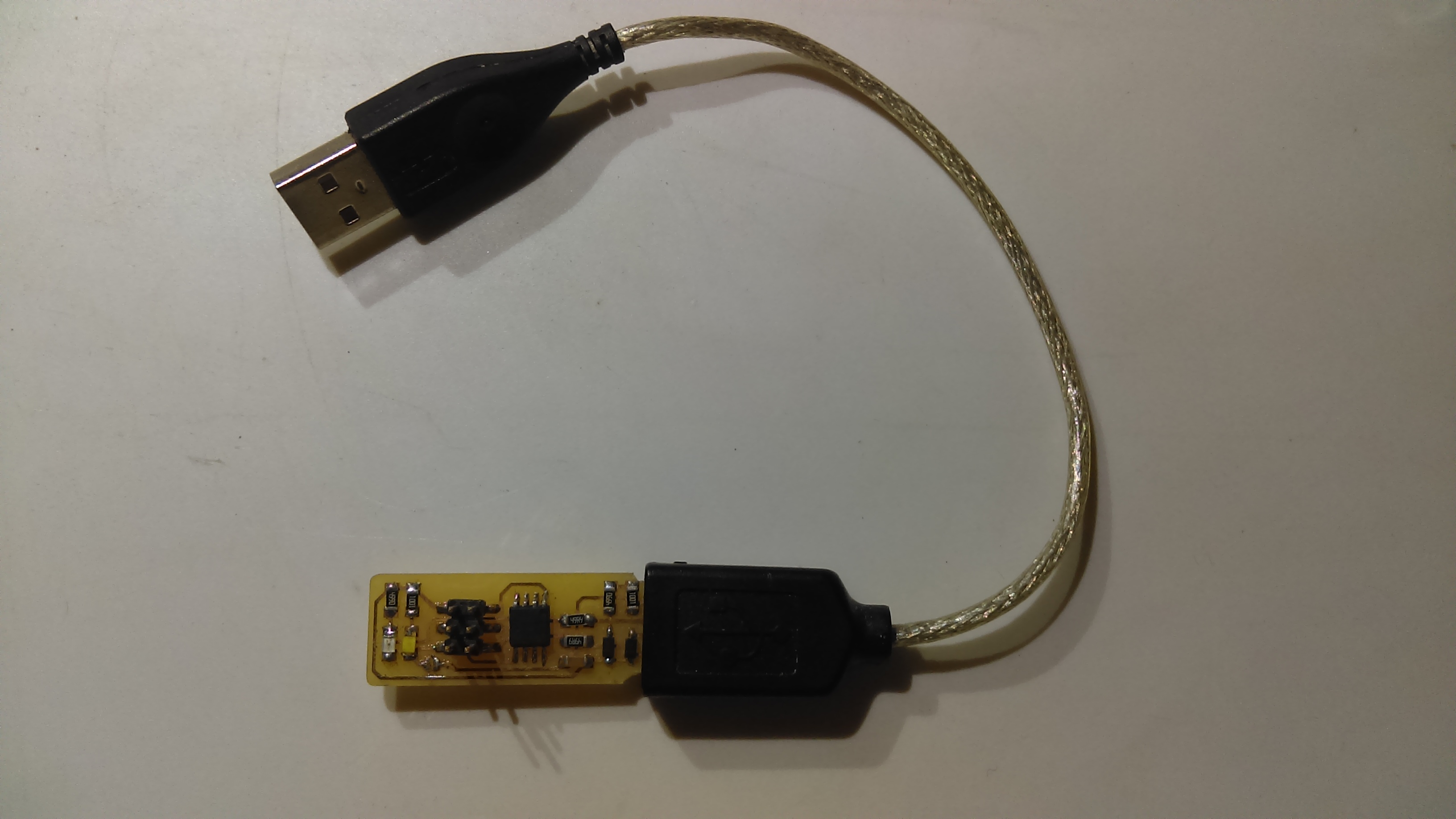
From the different design of the FABISP, I have decided to make several formats, the version with a mini usb connector and the version with the usb connector on the board, which uses fewer components. from the two png file cutting and paths, I used the fabmodules version to create the file for the cnc that we use in the fablab.

configuration of fabmodules, we must create two files for this plate, one that corresponds to the external cut and another one for the creation of the traces of our board. Import: for both files we select the type of file that we are going to import (png), that must have a minimum resolution of 600dpi Output format: Roland mill (.rml) that is the format that accepts our cnc
- Traces:
- PCB traces (1/64)
- PCB outline (1/32)
- PCB traces (0.010)
- wax rough cut (1/8)
- wax finish cut (1/8)
- Outline:
- PCB traces (1/64)
- PCB outline (1/32)
- PCB traces (0.010)
- wax rough cut (1/8)
- wax finish cut (1/8)
Cuts configurations
- Outline:
- machine: SMR-20
- x0 (mm): 0
- y0 (mm): 0
- z0 (mm): 0
- xhome (mm): 0
- yhome (mm): 0
- zhome (mm): 10
- Process: (THIS CHANGES DEPEND IS IF TRACE OR OUTLINE)
- cut depth (mm): 0.6
- stock thickness (mm): 1.7
- tool diameter (mm): 0.79
- number of offsets (-1 to fill): 1

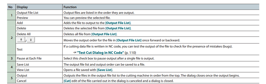
Save .rml file
Cutting in SMR-20 vPanel
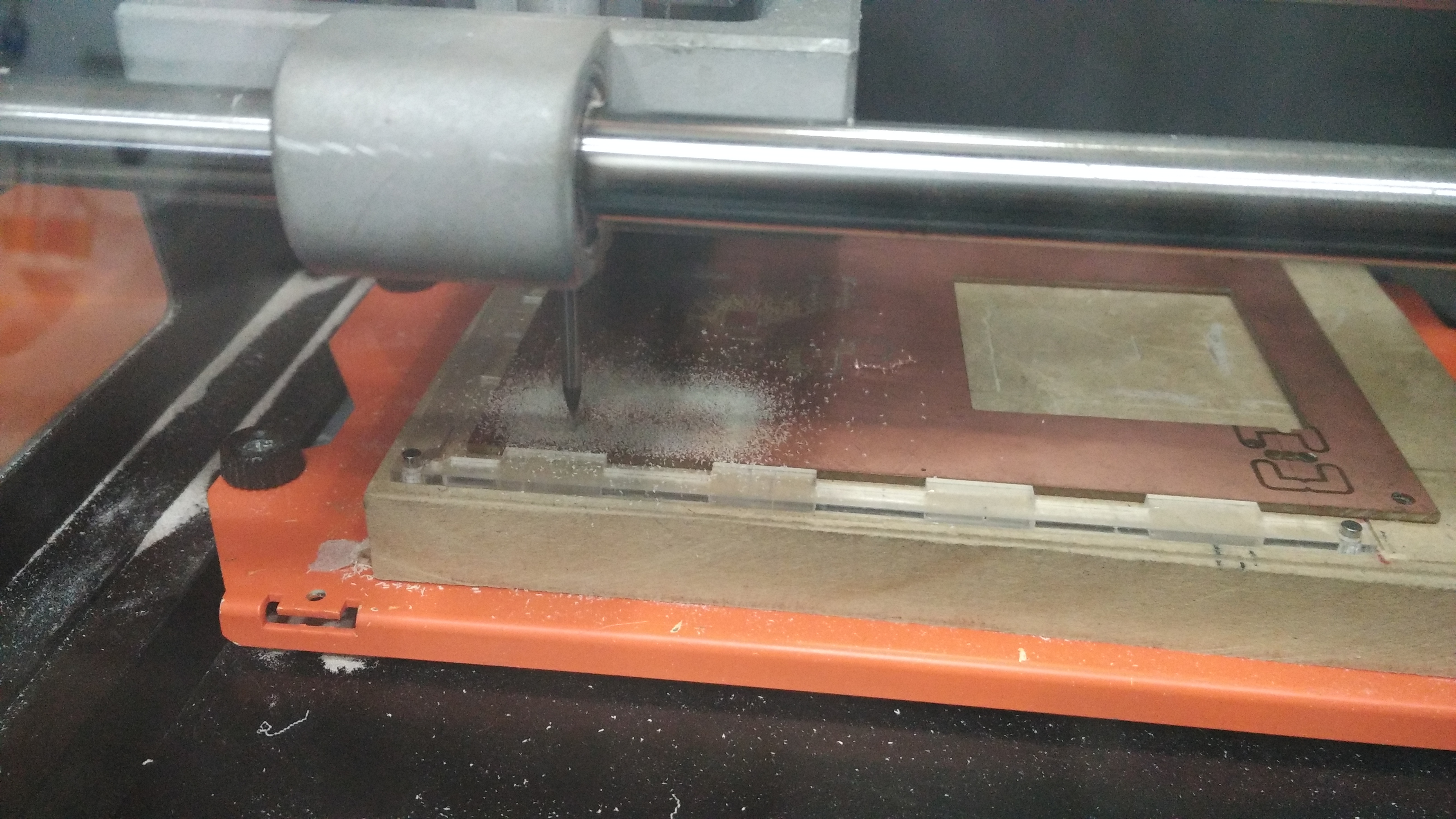
Before sending to cut our table is necessary to fix it in the platform of the machine, for this is used double-sided tape, since it is perfectly adapted to the platform and allows us to remove it without any difficulty when finished cutting the plate.
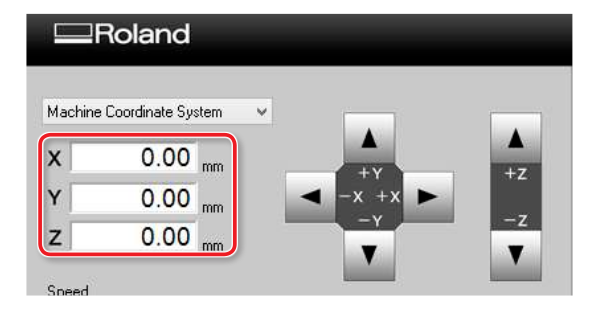
This is the control panel that we will use to configure the machine and send the files to our boards.

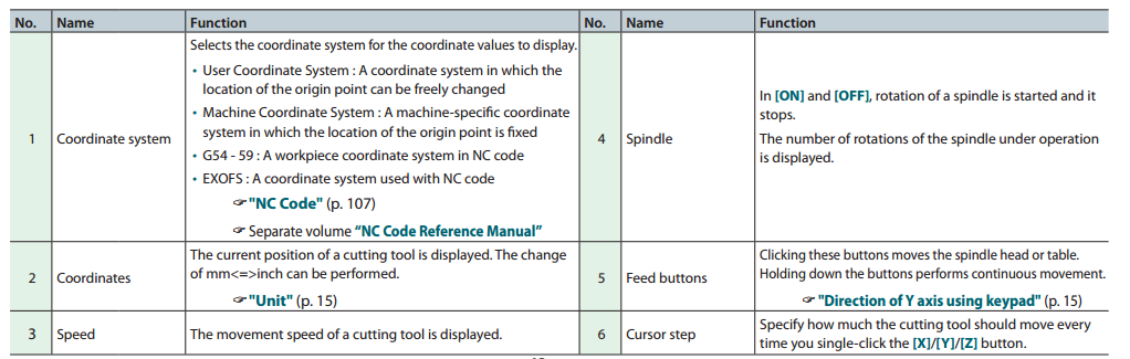
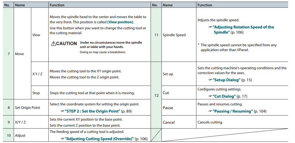
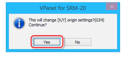
Configure file in SMR-20 vPanel (CUT)

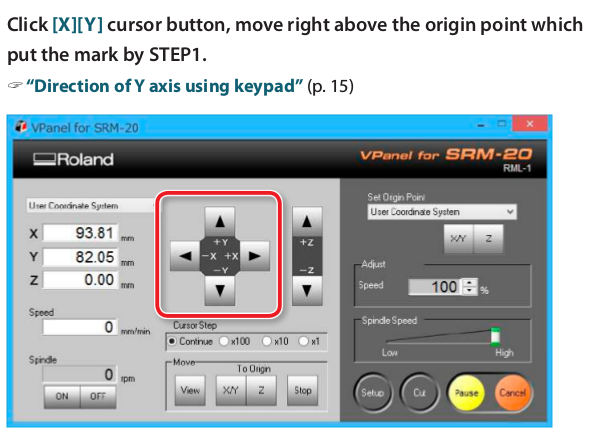
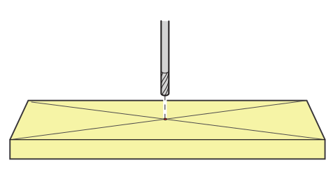
Set the Origin Point (XYZ)
The X and Y origins are determined by the cutting data and the location of the material. (“X” and “Y” cannot be set individually.) You normally align the Z origin with the surface of the material. Take the size of the material and the length of the cutting tool into consideration when you set the origins.


Final Process
Once we have the generated files and we have understood how to fit the cnc to create our plates, we must add this to the plaform with double-sided tape, and make sure that it fits perfectly to this, to set the milling and execute our file to cut the tracks , when this is finished, we change the miling to cut the contour and execute the corresponding file.

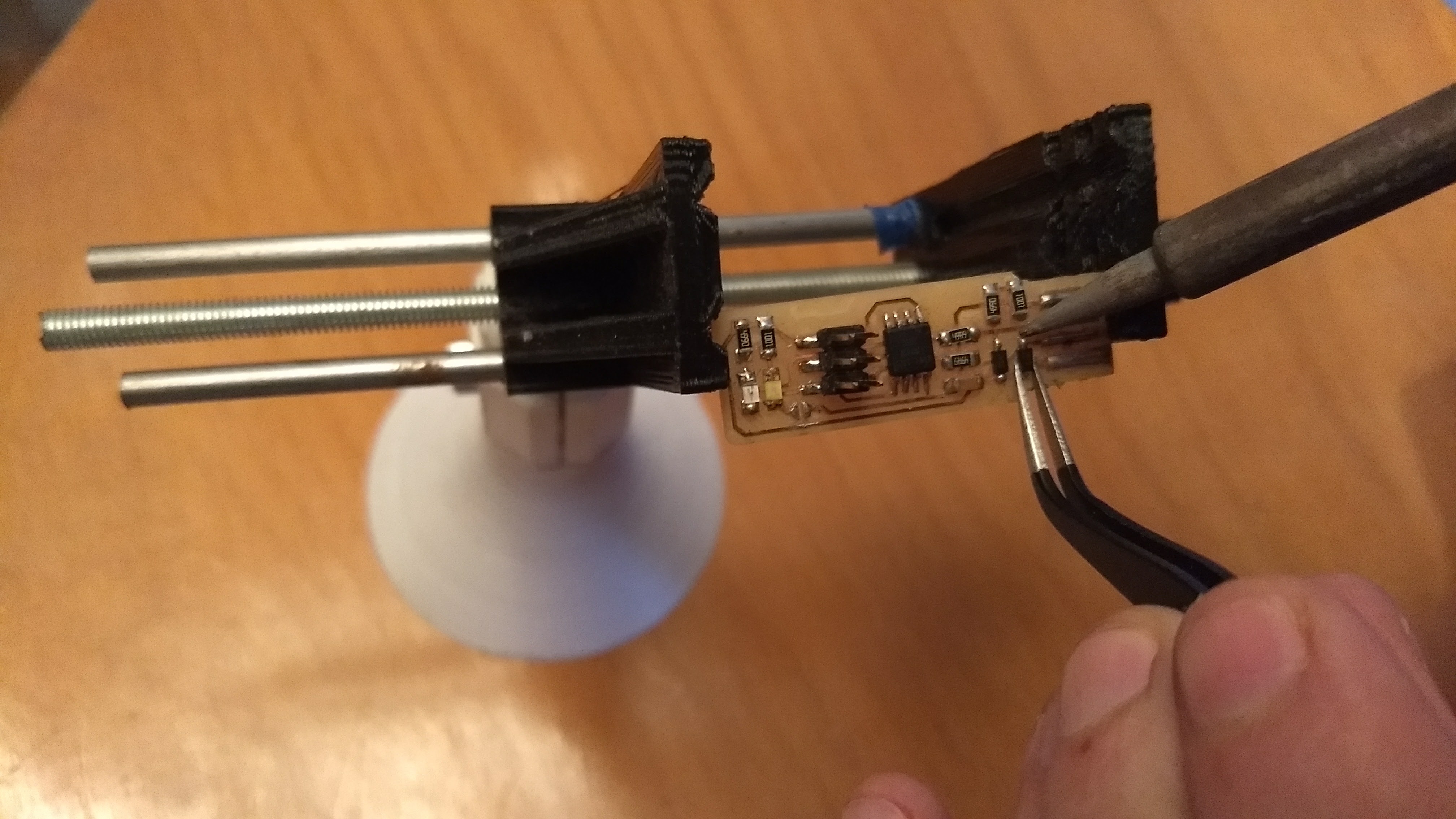
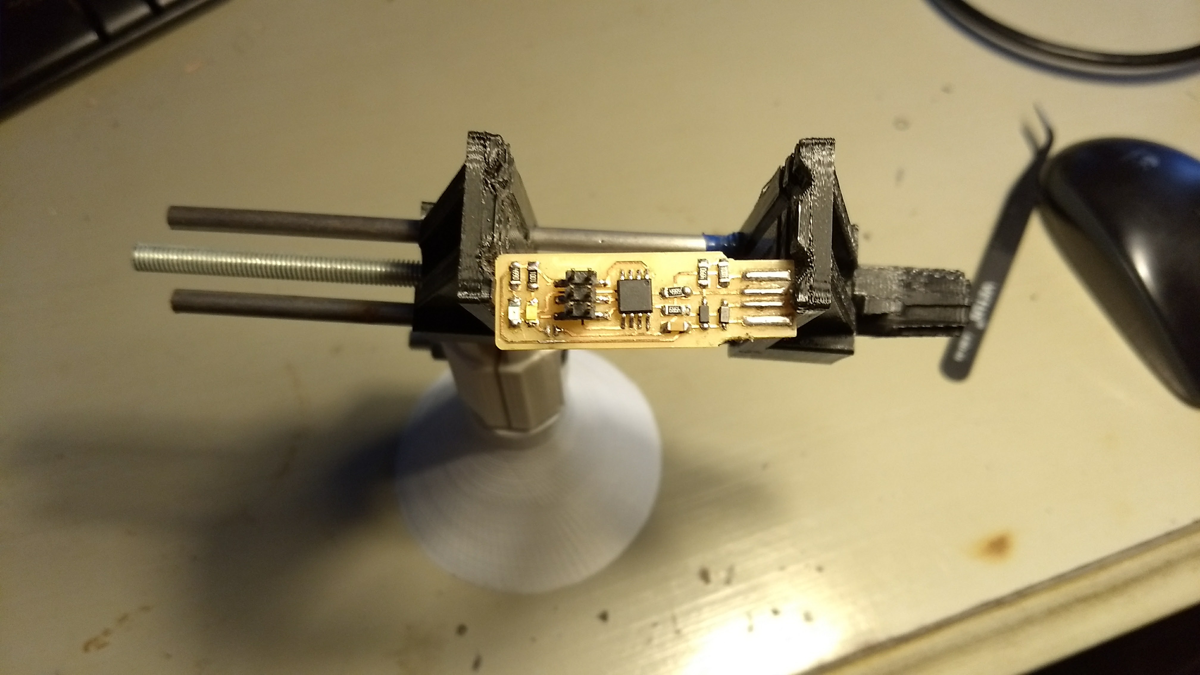
To weld the smd components to our plate I like to use the vise that we have in the lab, since it allows me to have the plate fastened correctly, I use a pair of pliers so that the components do not move from their place, only It is necessary a little practice to obtain a good result, besides having the welder and the tips in perfect conditions.
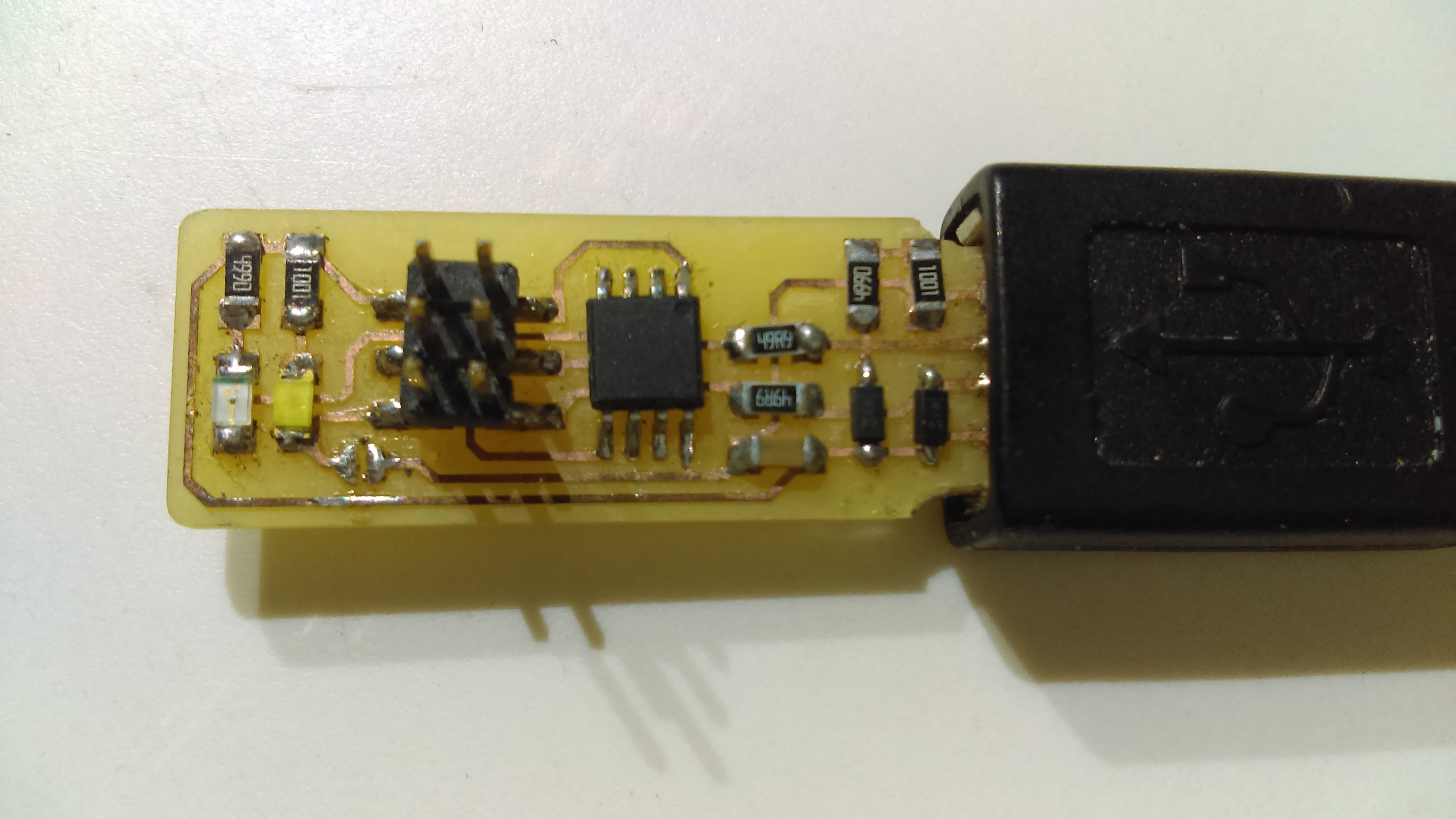
UBS connector in pcb details
Programing board connections
I work on linux and normally work with the design of boards, so I have already installed all the tools to work with microprocessors of the AVR family </ p>
But for anyone who wants to program their microcontrollore in linux you need to install some packages
1
2
3
sudo apt-get install gcc-avr binutils-avr avr-libc

sudo apt-get install avrdude

AVR Fuse
The fuse is a very important part when programming our microcontroller, an error in the fuse can leave to break of the own chip, the fuses define how our chip should act, whether it has an external oscillator, the speed of the clock, whether it contains a bootloader, voltages and what it will work, protection to protect the program, etc. The important thing about fuses is that they can be reset and changed constantly.
Each type of process has different fuse settings.
1
2
3
4
5
6
7
8
9
10
11
12
13
14
15
16
17
18
19
20
21
22
23
24
25
26
27
28
29
30
31
32
33
34
35
36
37
38
39
40
41
42
nanu@nanu-ThinkPad-X220:firmware$ make fuse
avrdude -c usbtiny -p attiny44  -U hfuse:w:0xDF:m -U lfuse:w:0xFF:m

avrdude: AVR device initialized and ready to accept instructions

Reading | ################################################## | 100% 0.01s

avrdude: Device signature = 0x1e9207
avrdude: reading input file "0xDF"
avrdude: writing hfuse (1 bytes):

Writing | ################################################## | 100% 0.00s

avrdude: 1 bytes of hfuse written
avrdude: verifying hfuse memory against 0xDF:
avrdude: load data hfuse data from input file 0xDF:
avrdude: input file 0xDF contains 1 bytes
avrdude: reading on-chip hfuse data:

Reading | ################################################## | 100% 0.00s

avrdude: verifying ...
avrdude: 1 bytes of hfuse verified
avrdude: reading input file "0xFF"
avrdude: writing lfuse (1 bytes):

Writing | ################################################## | 100% 0.01s

avrdude: 1 bytes of lfuse written
avrdude: verifying lfuse memory against 0xFF:
avrdude: load data lfuse data from input file 0xFF:
avrdude: input file 0xFF contains 1 bytes
avrdude: reading on-chip lfuse data:

Reading | ################################################## | 100% 0.00s

avrdude: verifying ...
avrdude: 1 bytes of low fuse verified

avrdude: safemode: Fuses OK

avrdude done.  Thank you.
Programing
To program the chip with the firmware the "make" command is used, this command allows us to create different configurations depending on what we want to do to our chip. like for example to record the fuse, to compile/recompile the code, etc. thus configuring this file we can indicate the family of the chip and the programmer to be used. the -c flag is used to indicate the programmer and the -p family to which the chip belongs.
1
2
3
4
5
6
7
8
9
10
11
12
13
14
15
16
17
18
19
20
21
22
23
24
25
26
27
28
29
30
31
32
33
34
35
36
37
38
39
40
41
42
43
44
45
46
47
48
49
50
51
52
53
54
55
56
57
58
59
60
61
62
63
64
65
66
67
68
69
70
71
72
73
74
75
76
nanu@nanu-ThinkPad-X220:firmware$ make program
avrdude -c usbtiny -p attiny44  -U flash:w:main.hex:i

avrdude: AVR device initialized and ready to accept instructions

Reading | ################################################## | 100% 0.01s

avrdude: Device signature = 0x1e9207
avrdude: NOTE: FLASH memory has been specified, an erase cycle will be performed
         To disable this feature, specify the -D option.
avrdude: erasing chip
avrdude: reading input file "main.hex"
avrdude: writing flash (2020 bytes):

Writing | ################################################## | 100% 5.68s


avrdude: 2020 bytes of flash written
avrdude: verifying flash memory against main.hex:
avrdude: load data flash data from input file main.hex:
avrdude: input file main.hex contains 2020 bytes
avrdude: reading on-chip flash data:

Reading | ################################################## | 100% 3.36s


avrdude: verifying ...
avrdude: 2020 bytes of flash verified

avrdude: safemode: Fuses OK

avrdude done.  Thank you.

avrdude -c usbtiny -p attiny44  -U hfuse:w:0xDF:m -U lfuse:w:0xFF:m

avrdude: AVR device initialized and ready to accept instructions

Reading | ################################################## | 100% 0.01s

avrdude: Device signature = 0x1e9207
avrdude: reading input file "0xDF"
avrdude: writing hfuse (1 bytes):

Writing | ################################################## | 100% 0.00s

avrdude: 1 bytes of hfuse written
avrdude: verifying hfuse memory against 0xDF:
avrdude: load data hfuse data from input file 0xDF:
avrdude: input file 0xDF contains 1 bytes
avrdude: reading on-chip hfuse data:

Reading | ################################################## | 100% 0.00s

avrdude: verifying ...
avrdude: 1 bytes of hfuse verified
avrdude: reading input file "0xFF"
avrdude: writing lfuse (1 bytes):

Writing | ################################################## | 100% 0.00s

avrdude: 1 bytes of lfuse written
avrdude: verifying lfuse memory against 0xFF:
avrdude: load data lfuse data from input file 0xFF:
avrdude: input file 0xFF contains 1 bytes
avrdude: reading on-chip lfuse data:

Reading | ################################################## | 100% 0.00s

avrdude: verifying ...
avrdude: 1 bytes of lfuse verified

avrdude: safemode: Fuses OK

avrdude done.  Thank you.
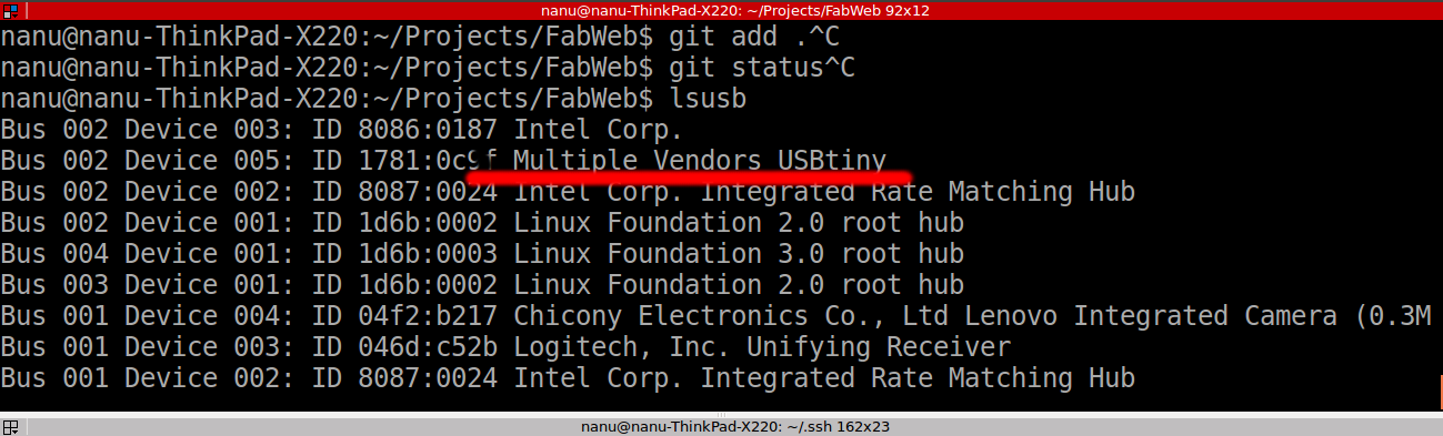
To verify that our board works correctly simply connecting it to our computer and using the command linux:
1
nanu@nanu-ThinkPad-X220:firmware$ lsusb