This week our focus is on Computer Aided Design in 2D and 3D environments. We should select, download, install and then try out various different types of 2D and 3D design and modelling software. To learn about and try to evaluate their specific uses, suitability and integration in the design process...
The main objectives are to gain a general introduction into computer modelling, assessing the distinctive types and their uses and application. We will use raster and vector based programs for image editing and drafting in 2D, then transitioning into 3D including; modelling, rendering, animation, CAD/CAM and simulation of our designs. Working toward a final main project concept.
In just a short time we have undergone a very condensed overview about several different types and styles of both 2D and 3D design software. Much inspiration and important information has been gleamed this week! I have undoubtedly gained many new conceptual ideas, learnt some technical processes and direct modelling techniques, and acquired more understanding of workflows and design methodologies.
Tutorials were given in the lab by very knowledgeable instructors who come in from different departments. Each had their own first-hand experience, expertise and preferences relating to one or other, or using different combinations of programs and software.
It has been a very interesting and invigorating process to be introduced to such a wide range of flexible and powerful design tools. Though at times I have felt a little daunted and quite overwhelmed by the full breadth and detail of what we are covering. I realised my current experience with CAD software was really quite limited to only basic functions, and also somewhat outdated compared to what is now possible! I am excited to learn and start engaging more with these tools and processes, knowing it will certainly be a long and ongoing journey to keep practicing with these programs, following tutorials, seeking guidance online and asking for help from tutors and colleagues to get a better understanding and confidence using the software whilst I work on my projects.
One of the first big issues you might consider when installing new software is comparing that of 'Open-source' software to that of more 'proprietry or commercial licensed' packages. 'Opensource' or 'freesource'; where the original source code is open and freely available - such as Gimp, Inkscape or FreeCad, have clear benefits in that they are readily and easily available to everyone. Also, being open-source there is often a better community involvement and forums for updates, extensions, program hacks, tweaks, expansions, plug-ins and developer tools. Allowing better evolution and more personal customisation and adaptation to meet ones individual needs.
.jpg)
.jpg)
.jpg)
.jpg)
.jpg)
.jpg)
In contrast are programs offered by long-standing bigger commercial proprietry software companies. Often these have more inherent stability, with less development issues but also carry the necessary licensing activation, and a heavy pricing. With the extra layers of security and structure for privacy and ownership built into the architecture, there is less potential for tweaks and hacks, but potentially more stability and customer support. This can be seen as both a strength or a weakness depending on your perspective. However, an obvious limitation is on the final user market and accessibility, with the inability to open and edit certain file types if you dont own a licence and your own version of the software. We will be spending a considerable amount of time studying the different types of program. Really trying to get a good feel for the tools, capabilities and merrits of using each package. And finding our own comfort-levels and areas of interest. We will then have a better idea and make the right choices to engage with each tool for our particular needs.
To evaluate; there are key commonalities and also big differences between software types. With 2D media a primary consideration between software for images is whether you will be dealing with either; Vector based - fully scalable point and path geometry. Or with Raster/bitmap, pixel based image files. We were suggested some good free-source options to try, alternatives to the well-known giants of Adobe -'Photoshop' and 'Illustrator', these were 'Gimp' and 'Inkscape'. I have been familiarising myself with both of these as I work on my project and files in a 2D plane. The clean simple layout and output of .svg files is especially useful, as they can then output to control vinyl or laser cutters. When it comes to technical 2D-3D drafting for dimensional accuracy and precision and drawing tools AutoCad (.dwg/dxf) is one well known powerful route to go, or for free open-source option there is Q-Cad. With accurate technical orthographic plan drawings, these can be output to generate 3D models or within 3D modelling packages for further editting, manipulation, renderings or animations.
Working environment and interface, things such as views panels, tool palettes, menus, controls and key commands, customizability and user preferences. The speed, adaptability, output, expansion capabilities, compatability and stability. Are all some of the things one may consider when deciding on the best software for the task. Particularly when relating to 3D software and beyond! it becomes ever more complex with many new things to consider... such as core mathematics, architecture, surface and geometry style and the physics used by each program - depending on their modelling style, suitability and functionality.
Sequences of events, pattern of commands in a program; it's history, the memory levels, back functions, controls and features all have an affect on your work flow and interaction within the program that directly effect final results. Even with the primitive construction of elements and objects themselves, that are generated within the virtual space that the software provides, setting up the relationships, parameters or constraints for these objects in accordance with each another and the environment design scale, can become an increasingly important consideration from the out-set in order to streamline your workflow and maximise the design capabilities. Understanding these parameters, constraints and definitions for your project is of key importance when designing each part. There are many very powerful tools for 3D content generation, manipulation and presentation to use for creating testing and prototyping your ideas, and ultimately manufacturing and producing some great designs.
I downloaded and installed a selection of programs both on an old Windows PC, and also my OSX macbook that I am using currently. This gives me opportunity for a broad look at what is available and I can test out some features and follow some tutorials for each and try to familiarise myself with commands and brush up on my modelling skills and my general understanding of digital content creation software.

I feel that each software package has their own inherent strength power and functionality, whilst also each will have limitations and drawbacks. Generally a specific software package is good at doing the task it was built for, with some potential scope for expansion or flexibility at doing other tasks. Often different packages their functions and workflows overlap and generally speaking it comes down to personal experience, and your prime intentions for the final output such as; screen based presentation and visualisations, print, moving visual and video, a simulation or a part file for manufacture. It will depend highly on personal preference which program to choose and to use.
For example SolidWorks - a well established, accurate 3D dimensional algorithm based mathematical engineering tool. This may well be an ideal engineers choice for direct detailed manufacturing using vectors, visualisation and testing of real parts components and assemblies to be made. Whereas Cinema 4D, 3DS Max and Maya in contrast may be far more suitable for working with screen based presentations or for moving visuals with more effects for rendering lighting and animation. Adobe for instance people are likely to use After Effects for video compositing and Premiere for video editting.
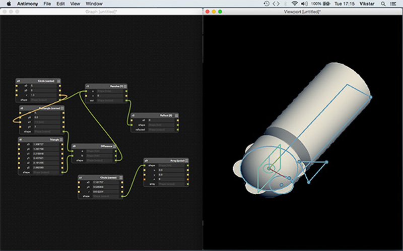
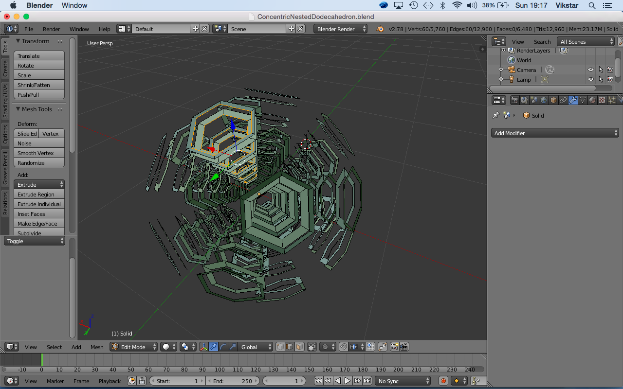
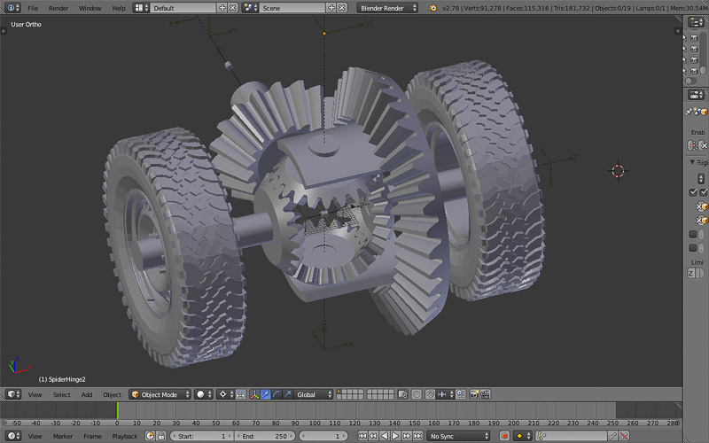
I have now installed Rhino, and SolidWorks which I am starting to familiarise with a little. I am currently also trying out Blender an opensource 3D package, and am in the process of slowly trying to get to grips with Grasshopper, which is a parametric node based plugin for Rhino. I also have had a try using Antimony by Matt Keeter, following the screw driver tutorial. Each software showed some interesting variations and differences and ultimately the user has great freedom in how they might go about their modelling process. Things such as setting up relationships, sequences of construction, degrees of freedom, restraints and constraints and how one may build or define a model. By setting these values and making the connections between objects aspects and artifacts that you build into your scene. Ultimately you can have fully parametrisized control of your model and modelling space this can become a hugely useful and powerful tool. Giving you adaptable scaleability and control to intuitively make changes updates within a moldable timeframe allowing various different itterations throughout the work flow as you build generate and improve on any given design.
This parametric approach, often known as a 'top-down design approach' is essentially the breaking down of a system to gain insight into its compositional sub-systems. In a top-down approach an overview of the assembly is formulated, specifying but not detailing any base level parts. Each sub-assembly and part is then refined in yet greater detail, sometimes in many additional levels, until the entire specification is reduced to base elements.
In top-down assembly design, one or more features of a part are defined by something in an assembly, such as a layout sketch or the geometry of another part. The design intent (sizes of features, placement of components in the assembly, proximity to other parts, etc.) comes from the top (the assembly) and moves down (into the parts), hence the phrase "top-down".
Solidworks, Fusion 360 and also FreeCad are all good examples of fully parametric software, plugins such as 'Grasshopper' for Rhino also enable parametric design capability.
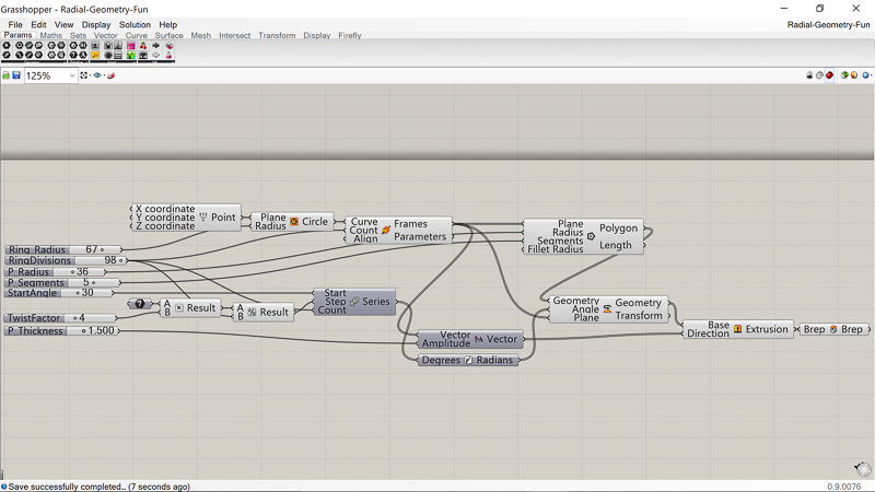 Grasshopper - Radial Geometry a
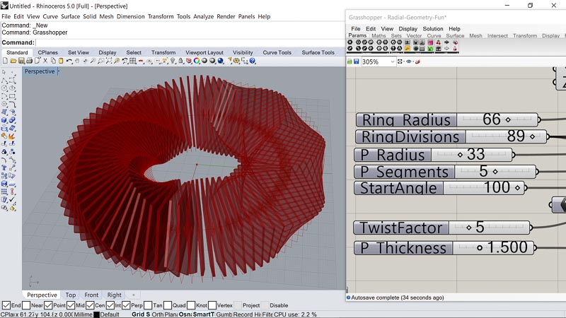 Grasshopper - Radial Geometry b
 Grasshopper - Hexagon bumpmap a
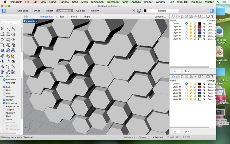 Grasshopper - Hexagon bumpmap b
 Grasshopper - Hexagon bumpmap c
In conclusion there are many good programs available and I have explored only a small handful, and to master but a few of these will take considerable time. But essentially they are tools that allow you to better achieve a goal. Which software to use depends on a number of criteria previously discussed and the merits between them are largely functional. Availability, compatibility and your needs. Some will inevitably contain useful features that others do not, some may be more suited to one workflow and design style, whereas others may be more related with another. I only hope in these coming weeks I have enough time to really get to grips with a few of the more powerful and capable packages I now have installed, and I look forward to creating some good looking designs.