Week 16 : Interfaces and application programming
This week's agenda for Fab academy was :
write an application that interfaces an input/output device that was made by me
Try as many interfacing tools as possible
Deciding the interface tool
For my final project, This week was very important, as the MIDI device is interfacing the arduino IDE script with Ableton and from Ableton it gets interfaced to Processing.
So, what is Ableton ? Ableton is a music production software, in simple words.In the website, a very simple description says "Live is software for creating musical ideas, turning them into finished songs, and even taking them onto the stage.With two views - the classic Arrangement View, where musical ideas are laid out along a timeline, and the unique Session View, where you can improvise and quickly experiment with musical ideas - Live is a fast, fun, intuitive way to make music" . It is an incredible software used by many professionals. Here , For my project I am using the trial version of Ableton Live 9.
This website lists Free music production softwares that can be used.
This website also lists a few more Open source music production softwares that can be used.
The reason why I chose Ableton is because, it is one of the most widely used software by professionals. There is a wide range of documentation and example files and resources to learn from.
Thank to Arnau, He helped me a lot in understanding how MIDI controllers work and how to map a MIDI. First, we tried with the Korg NanoKontrol and he taught me how to map the music to the MIDI buttons/keys.
Once I tried with the commercial MIDI controller, from my input design week, I had the arduino board programmed as the MIDI controller. Therefore, My arduino was working as a MIDI controller.
I went through a lot of tutorials before , to understand the Ableton Interface. Here, I list one of the begginner tutorial I followed
Now, With my arduino board working as a MIDI controller, I first tried with the commercial arduino board to interface with ableton.
I have to mention Controllerism, this website gave me most of the resources for my project. But most importantly, It was after going through various research documents and resources online, I finally stumbled upon this one and felt like I hit a jackpot!
Here, In this video, you can see me interfacing with arduino with ableton live.
Let me give a break down of what is exactly happening in the ABLETON SOFTWARE in this project and how it is interfacing it.First you make sure, in the MIDI sync tab under preferences in ableton, the input is buttons and the output is visuals. Buttons are the analogue input coming in from the microcontroller board via virtual MIDI ports.As mine is not a commercial MIDI controller, Ableton is not able to access any libraries to connect to the board. But with the virtual MIDI ports, it shows me the options of buttons and visuals. These have been set up in the virtual MIDI port, I have writtten more about virtual MIDI ports in the project development week.
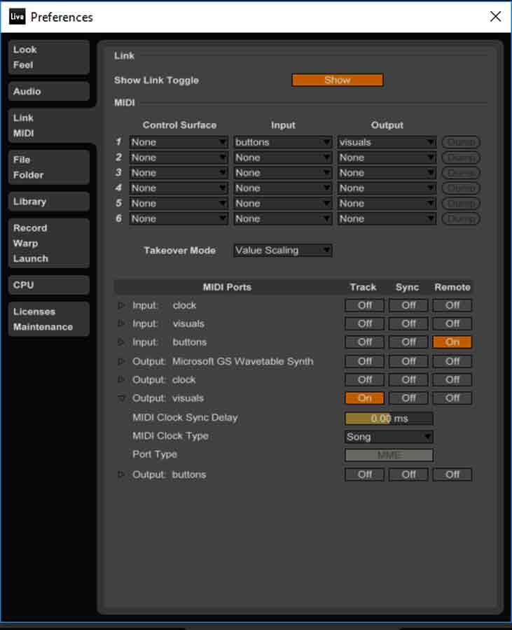
Once the MIDI is connected, In this ableton sketch we see four tracks, the drum kit, which initiates the tracks is linked with the visuals track. So the important thing to note here to interface the visuals and start the MIDI is to link the button that turns the music set on to the visual "+" , so this can kick off the drums and the visuals. Each kick core track is assigned / mapped to one analogue button connected to the microcontroller. In the MIDI mapping screen, you select a track, and click on a button and map that button onto the track.Any track that is needed can be dragged into the set and mapped onto the buttons.
This is how Ableton is interfacing with the circuit board connected to buttons.

In the input devices week, I have already spoken about how buttons are interfacing with my customised Satsha kit and ableton. But here is the video.
For my project, I also Interface with processing for generating real time visuals.Controllerism gives an in detail explanation of Ableton to Processing
Processing uses the The MIDI Bus Library to read the MIDI notes and convert it to graphics in real time.
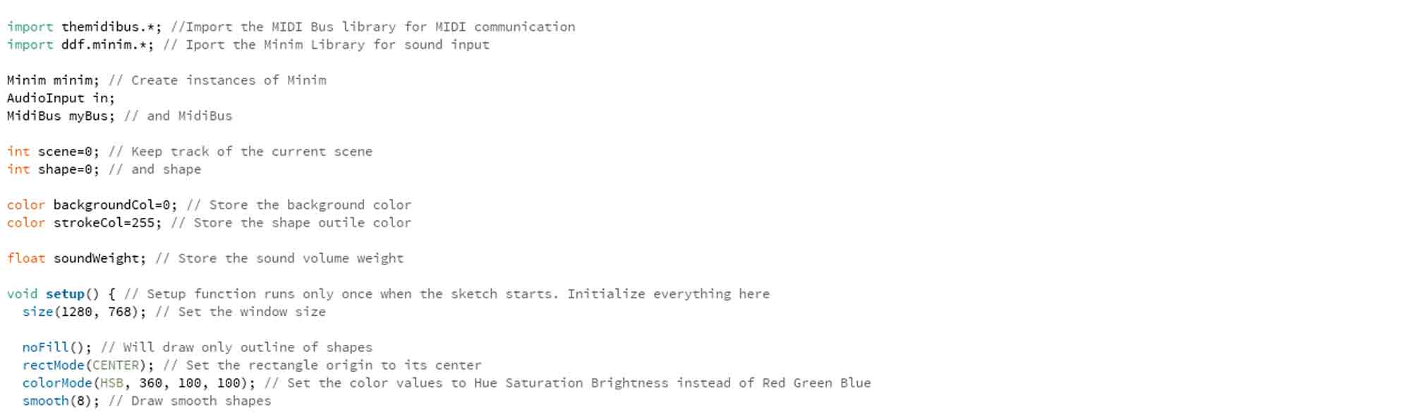
So, first we import the required libraries to the processing file. MIDI BUS for midi communication and MINIM for sound input. and set up the basics of the code. so the scene, background , void set up etc., like how we do for every project, but here, there will be a float - sound weight to store the volume of the weightof sound.
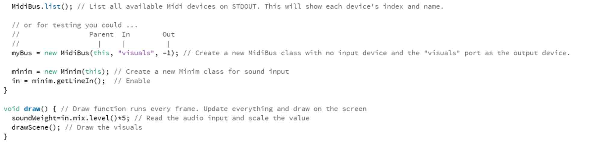
We then "list" the MidiBus. while doing this, the most important part to remember is , the myBus = new MidiBus ( "parent", "input" ,"output" ) in this the "input" has to be set to no input device but the "visuals" is actually the output. this "visuals" out sput is coming from our abletin track where we have defined "visual snare".in ableton, when we play the visual snare, the output of visuals is executed on processing.
As seen in the srduino code as well, everytime, we code for a midi translation, there is a "note on " note off" code written, which understands the translation of nubers to sound or sound to numbers oinside the code.
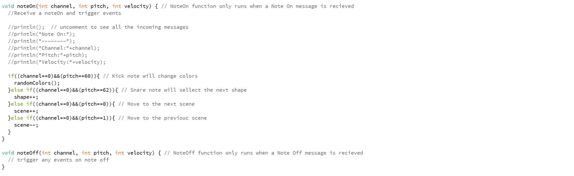
we then describe the scene of what and how the visuals need to be. here there are 3 cases, the background colour , the shapes and the movement of theses shapes according to the weight of sound. so that is the float defines in the beginning, as described.
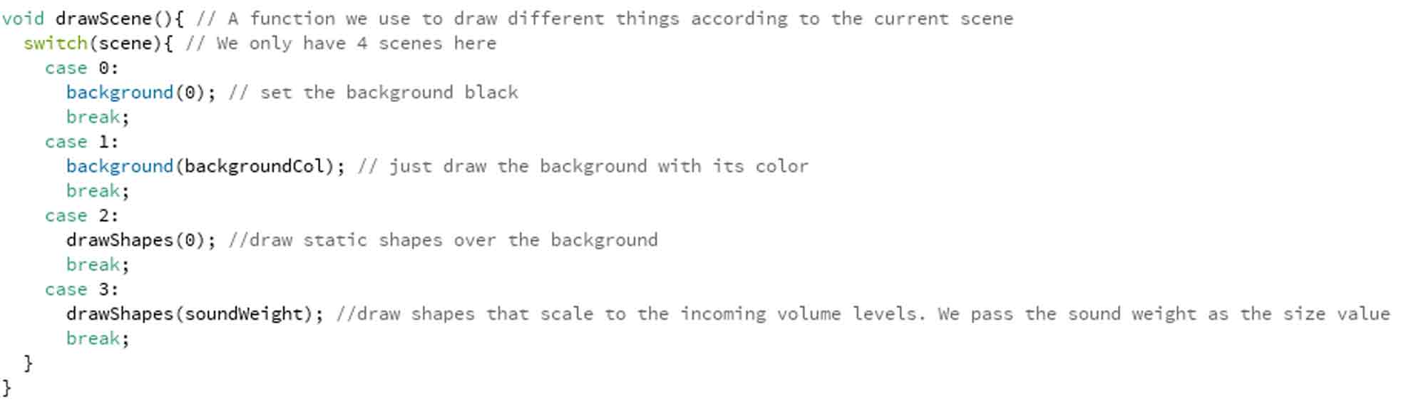
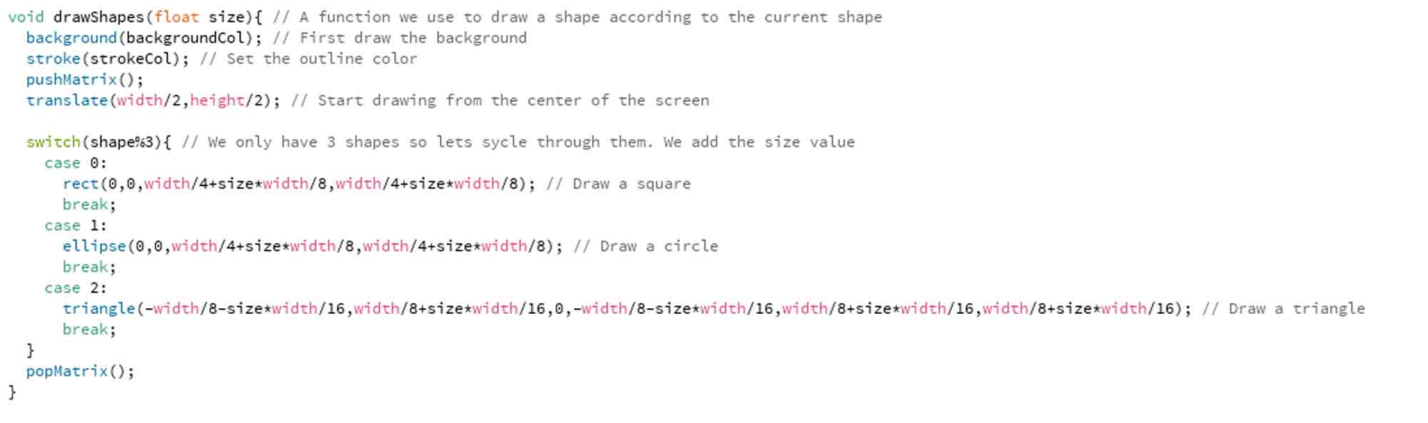
here we define the coulour of the background, and ask for the shape to start in the center, and the 3 types of shapes defined here are, square, circle and triangle.then we end the code.
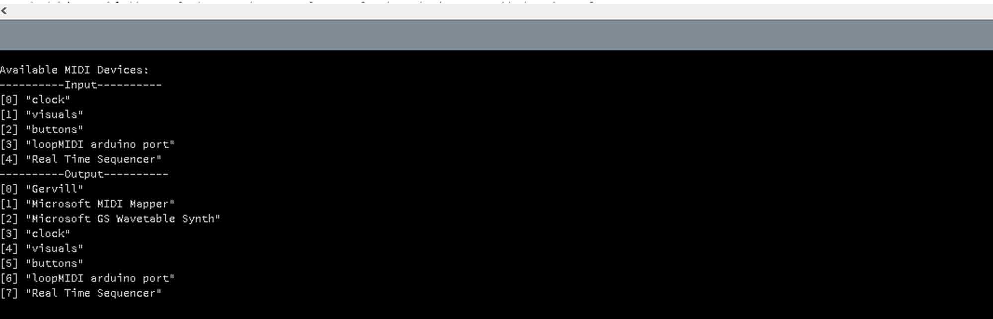
when we hit play on prcessing along with ableton running, the message window in processing shows us the available input and output devices. so it is easier for us to cross check.
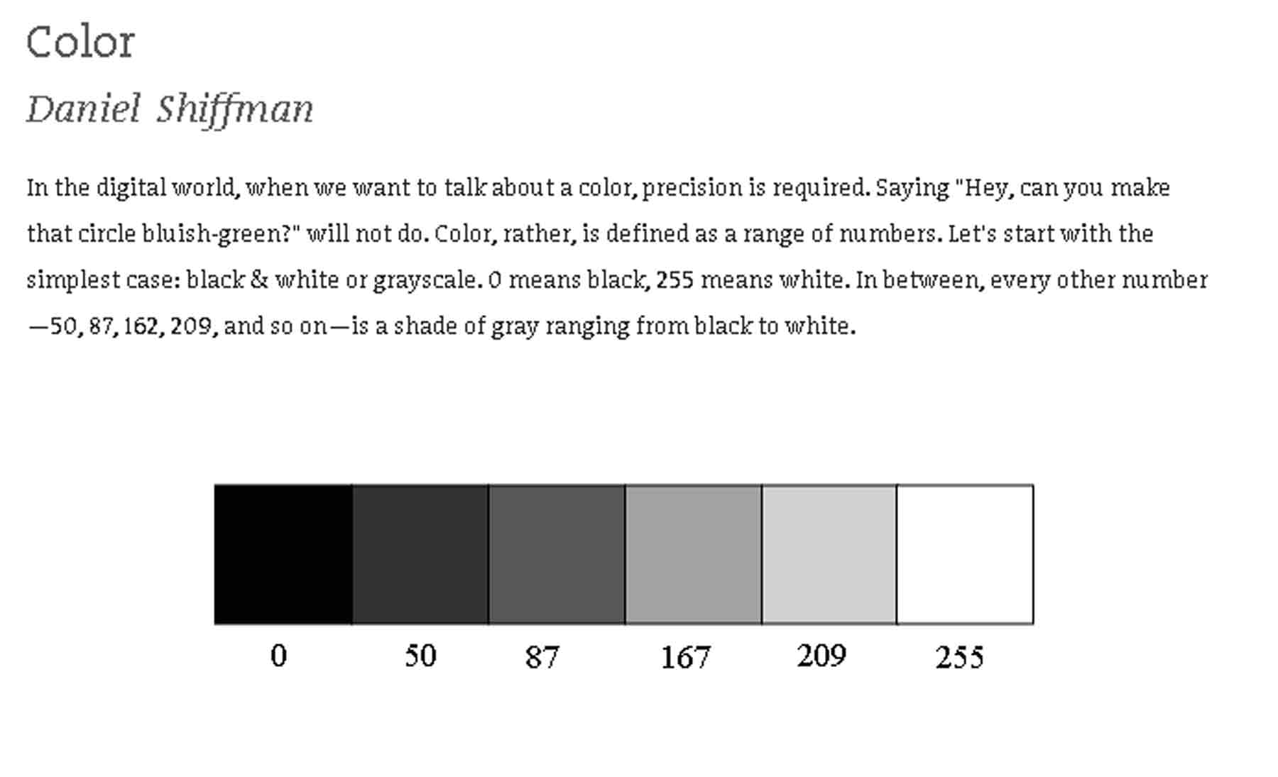
while learning this code from the web, I played with changing the code with different colours. I kept it tp black and white which are my favorite colours.But each number defines a colour and was a lot of fun playing woth different colours.
In my final project video, we can see the basic sketch to make squares bounce to the beat of the music.Here, the background is black and the shape of the square is white.
To view and download files click HERE
To download files click HERE
Interfacing by making a simple app for a project of mine
For this exercise, I wanted to revist a project I made during my graduate studies. It was a Zoetrope.
And one of the important features in a zoetrope is the stroboscopic light. After my research during my study, I had found that the speed of the stroboscope affects the perceived speed of the animation of the images. Faster the strobiscopic light, Faster the animation and visa versa.
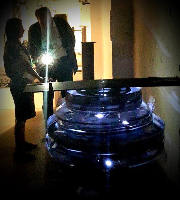
During my project, back then , I used a commercial app called Music Strobe which was free, where the flash light from the phone camera acted as the stroboscopic light for my zoetroe model. This flash light was responsive to speed of speech. The faster a person spoke, The faster the pulse of light and slower the speec, The puling of the flash from the phone was also slowed down.
For this exercise, I want to build an app, which works similarly but not the speed of speech as the input but the proximity sensor as the input. For this purpose, I will be using the MIT App Inventor to build an app to make the flash light of the phone work as a stroboscope.
With arduino, I have used a proximity sensor first and tried to turn on more number of leds with a achange in proximity.
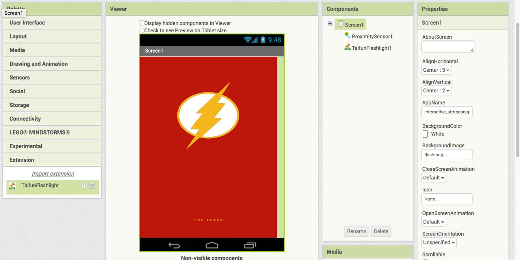
Now, I try with the MIT App Inventor.I read throughthe turorials on the webpage, and found it be easy and helpful.For the purpose of using Flash light, I had to add an extension to the app inventor. In this Link, you will find the app extension, and on the page, it is mentioned best to donate in order to use the app extension if we find this useful.
Once i had the app extension, now , i could use the flash light on the android phone.I do not need any buttons, All I would need is a proximity sensor. And I assigned a background image for the app.
Once I had all my components, I added the blocks in order to function as a stroboscope with some IF and ElSE statements.
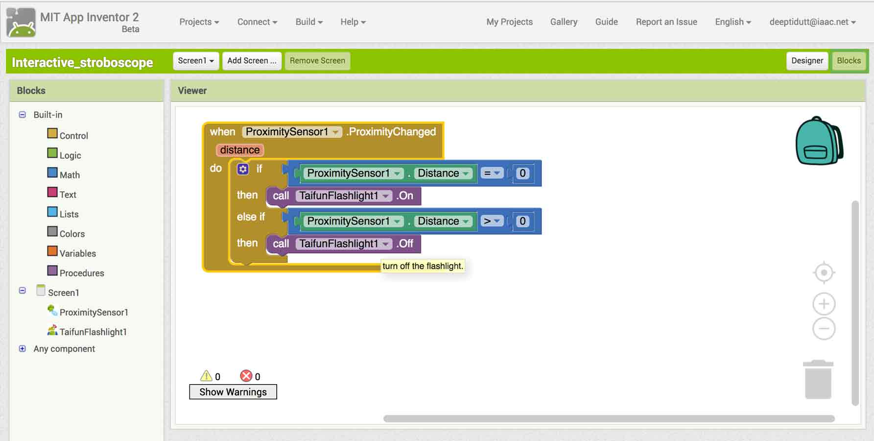
So, Now, I have the strobscope, The speed of which I can change manually by interacting with my app.Here is a video demonstrating my app.