11 - machine design
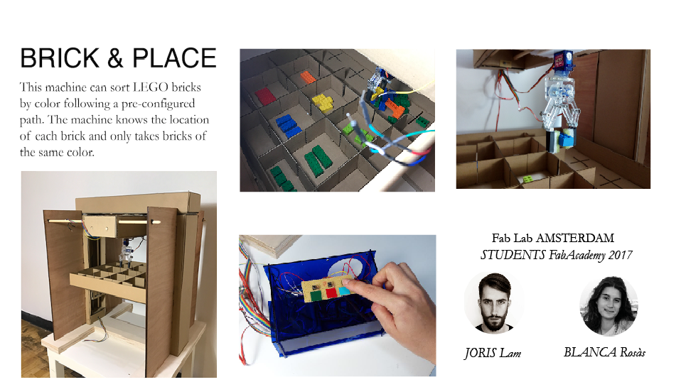
This is the group page of Blanca Rosas and Joris Lam from Fab Lab Amsterdam about their 'Brick&Place' machine.
On this page you will find the complete documentation, which is the documentation from week 09 on mechanical design plus new documentation from week 11.
MECHANICAL DESIGN
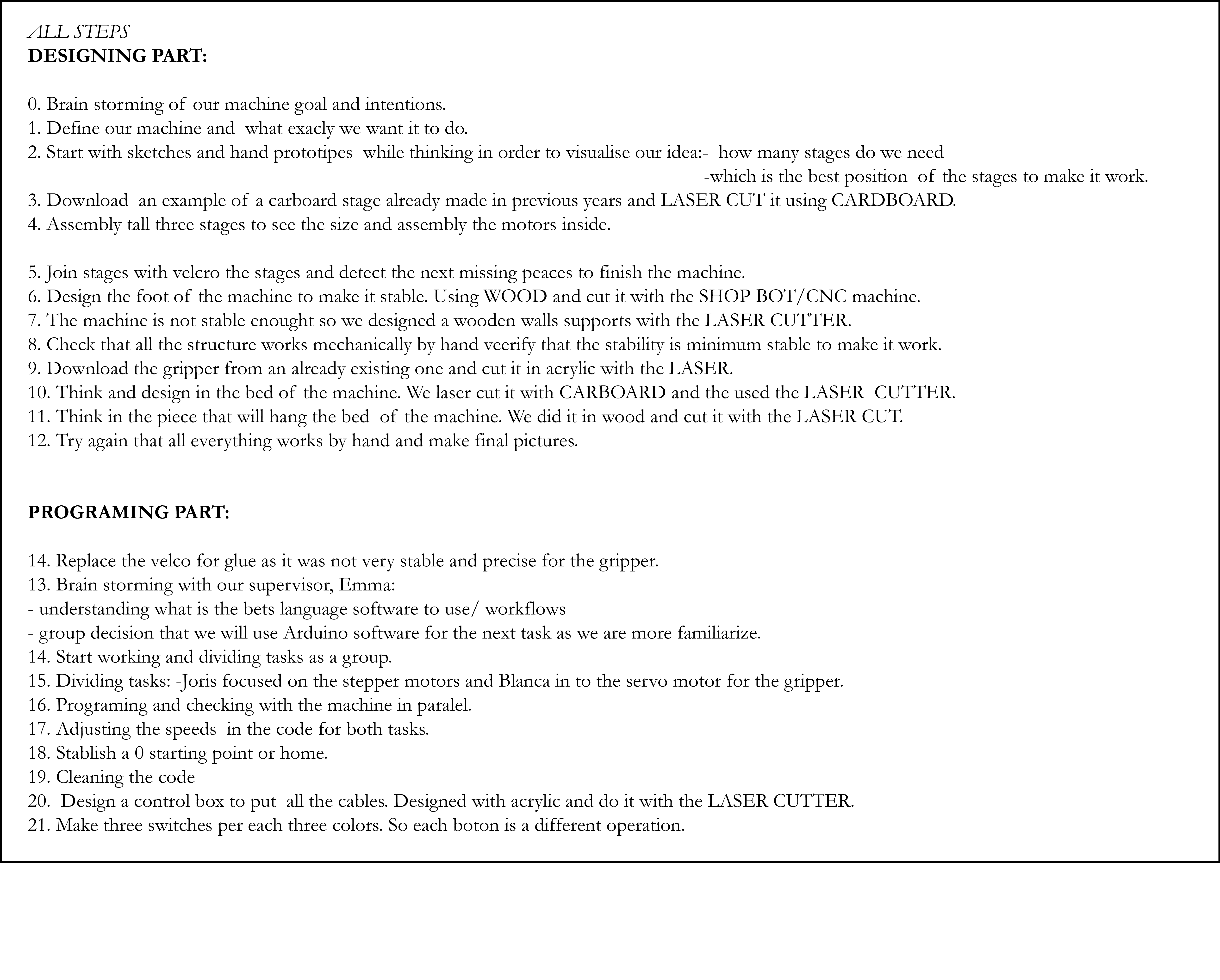
STEPS:
In short the steps we took where:
01 - concept and visualisation
02 - building the stages
03 - building structure around the stages to keep them in place
04 - making a gripper
05 - designing a bed
06 - final assembly
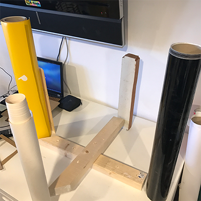
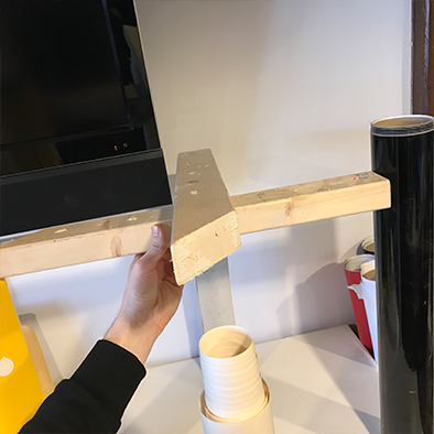
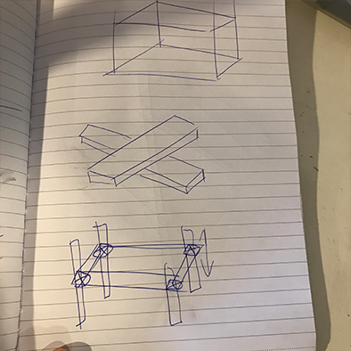
01 - concept and visualisation
To get a first idea of what we wanted to build we used simple materials from the lab to visualize ideas and the position of the stages. We then made sketches, but soon we found out that we needed to see what the stages look like in terms of size, stability and weight etc. so we quickly moved to making them.
02 - building the stages
To build the stages, we downloaded the files and instructions from this this page.
We used 3mm cardboard that we laser cut on our BRM laser cutter, and as soon as we had the parts we started glueing everything together.
These are the laser settings we used on a 100 watt laser:
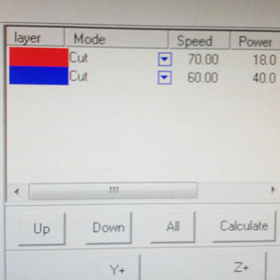
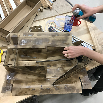
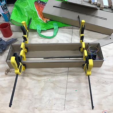
We used clamps to press everything together nicely.
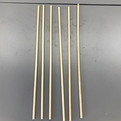
Our kit was missing aluminum rods in the right size, so we bought wooden rods instead.
We went on to assemble the moving part and attached the plastic part that screws onto the motor screw and added plastic rings to reduce friction.
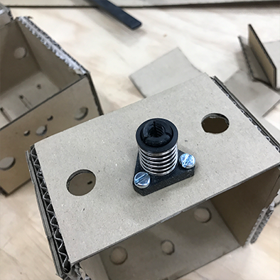
Fully assembled, the stage plus motor looked like this, and the last step is to add the front of the moving part which we covered in velcro.
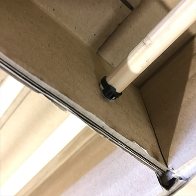
To keep the wooden rods from moving, we added small tie-wraps on either end to keep them firmly in place.
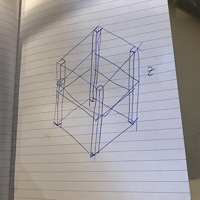
We made a total of three stages for X,Y,Z axis.
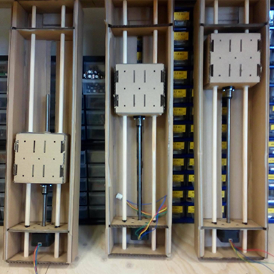
This is how we want to configure them:
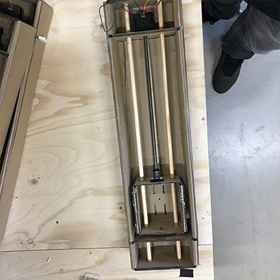
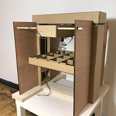
03 - building structure around the stages to keep them in place
After we had the stages we went on to build a structure around them to keep them in place. This is the point where things went a little murky in the process. The big mistake we made was in planning and designing the machine. We didn’t make a 3D design, or masterplan for the machine, in stead we just manually kept building and improving everything around the stages. If we would build the machine again we would take a different approach but it was very insightful to do everything manual/analog to really get a good feeling of what this machine requires and endures in terms of forces.
We divided tasks between the two of us, and Blanca got started with a base structure for the stages and I started working on the gripper.
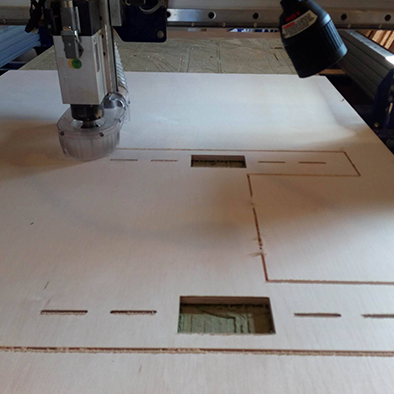
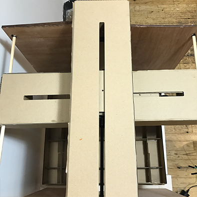
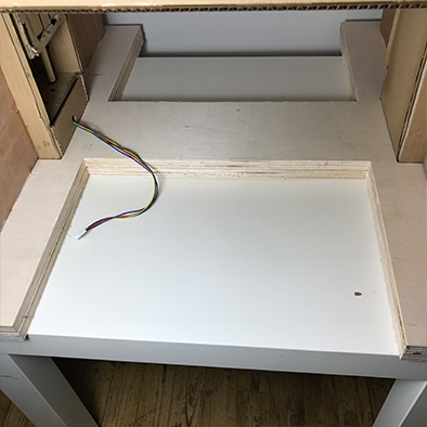
Blanca used the Shopbot to mill a sturdy base out of thick plywood, we made two and glued them together to get a nice and heavy base that keeps vibrations at a minimum.
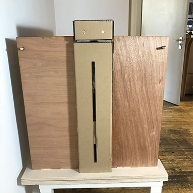
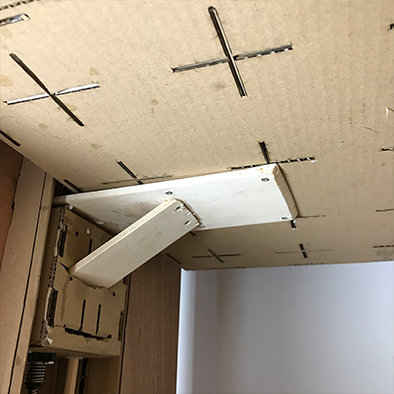
After we put the stages in the base that Blanca made, we had some doubts about the stability of the stage that holds the gripper, as it is placed underneath another stage. That is why we made a support system along the vertical stages that holds rods on which the stage can slide.
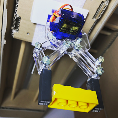
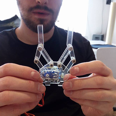
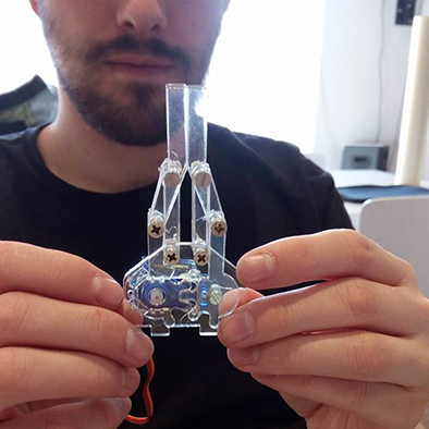
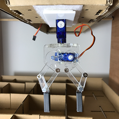
04 - making a gripper
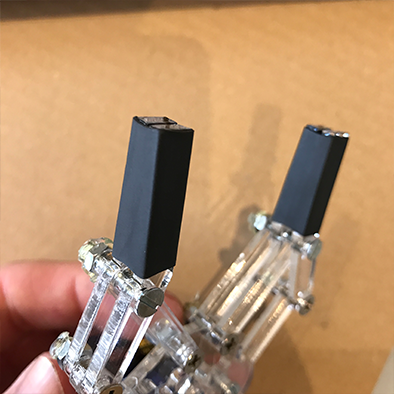
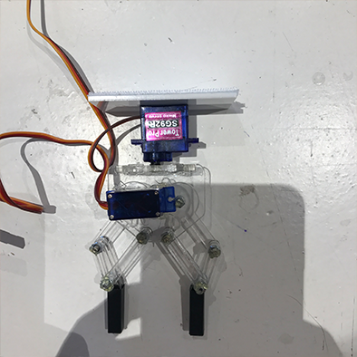
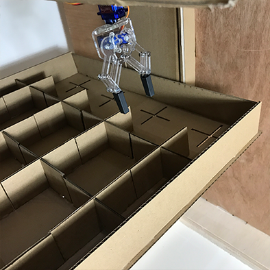
I worked on a mechanical gripper that can pick up bricks using a servo motor, I used this file from Thingiverse as the basic design. After laser cutting it out of 3mm acrylic I hacked some pieces together to make it more compact, make the servo fit better and I added shrink tubing around the end to give it a better grip.
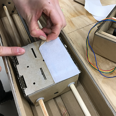
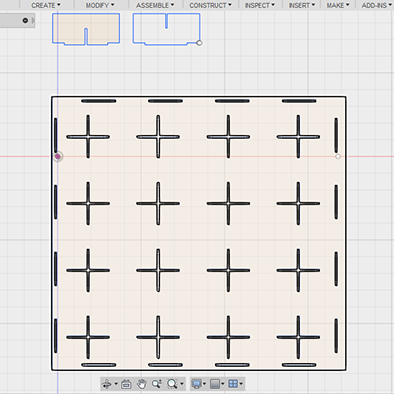
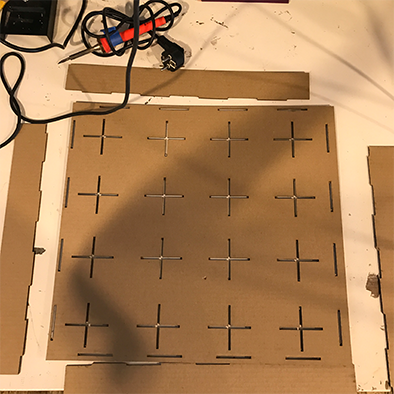
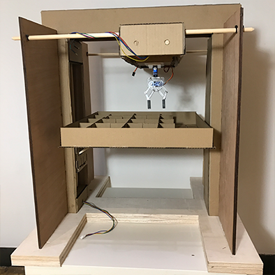
05 - designing a bed
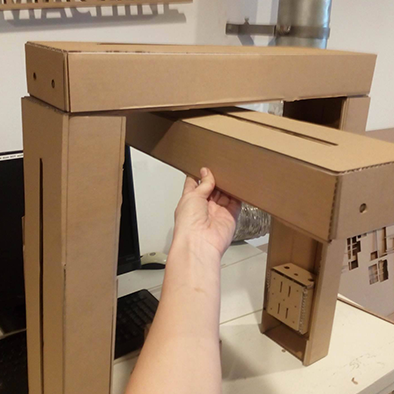
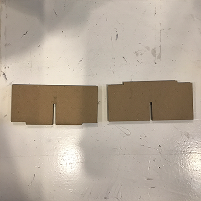
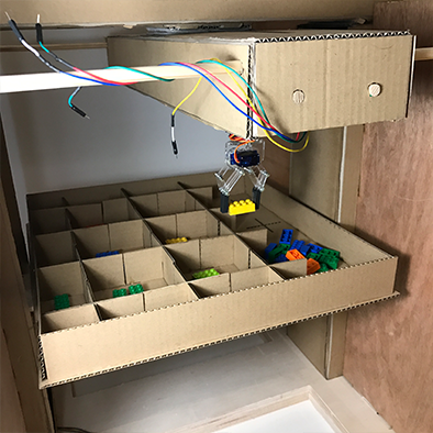
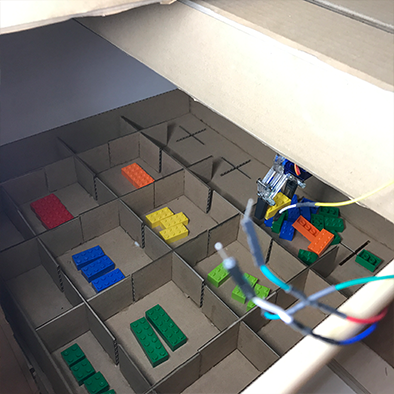
The last thing we designed and built was the bed of the machine, because the machine needs to hold a wide variety of parts and we wanted it to be reconfigurable we designed a bed that allows various dividers to be placed to create either small or big pockets.
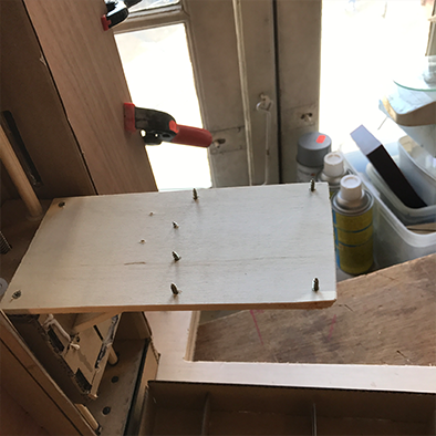
The bed rests on a wooden support that we drilled screws through to grip through the cardboard.
For the final assembly we tried to keep the machine easy to take apart and put together, so we used velcro to connect the stages to each other and to the gripper.
HERO SHOTS
ELECTRONICS, MOTORS & SOFTWARE
To start automatic the machine, we first got a lesson from our local instructor Emma on the different possibilities to drive the machine.
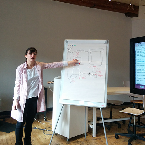
The different workflows are:
1 - g-code and grbl to go from a PC that generates g-code to motor drivers that drive the motors
2 - fab mods and Gstalt nodes to create a network that can be expanded infinitely
3 - standalone machine operating on Arduino and CNC shield
Because our machine ‘knows’ where each part is and follows pre-programmed paths, we chose to make a standalone machine that is controlled via it’s own control-panel and a button interface. The idea is that if you press the green button, the machine will gather all the green parts and put them in the same place, it works the same for other colors.
Before we got to any programming, we had to figure out how to control the stepper motors in the stages and the servo motor in the gripper. We split up and Blanca started working on programming the gripper and Joris started working on controlling the servos.
For the gripper servo we found and example of a code with arduino that worked for us:
https://programarfacil.com/tutoriales/fragmentos/servomotor-con-arduino/
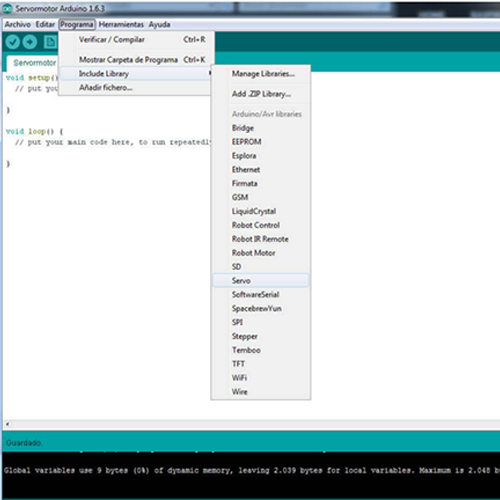
First of all you have to open Arduino software and you have to select a library to control the servo with Arduino.
To do so you need to go to the window PROGRAMS/ INCLUDE LIBRARY/ SERVO.
And then we will have copied this
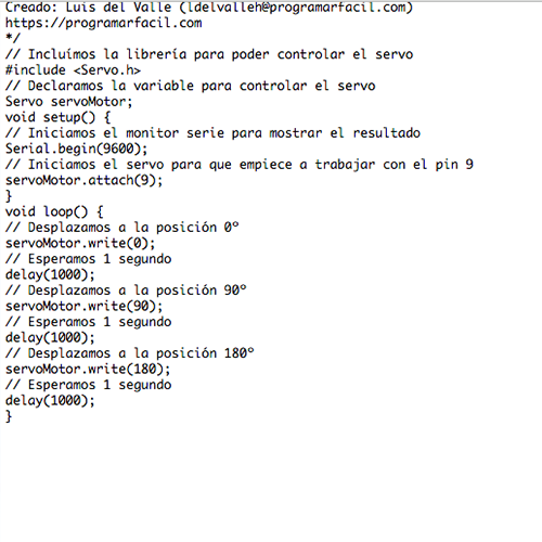
Finally we have to connect the USB cable from the arduino to our computer and first VERIFY and then LOAD.
We found out that the gripper was moving very fast so what we did is to change some parameters for the ones we wanted. To read more about the final code, scroll down.
To get the stepper motors to work, we used the CNC shield and an Arduino Uno.
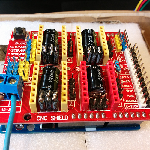
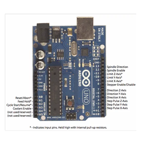
The CNC shield does not require any drivers or libraries as it simply passes the pins from the Uno on to different female headers, optimized for the job. Because we also wanted the Uno to drive the servo and handle button inputs, we had to use some of the pins that serve a different function according to the shield to do the things we needed specifically for this project. That is why we started by studying this handy pinout image.
The motor driver we used with the shield is the DRV8825. We used three of them, for X, Y and Z axis.
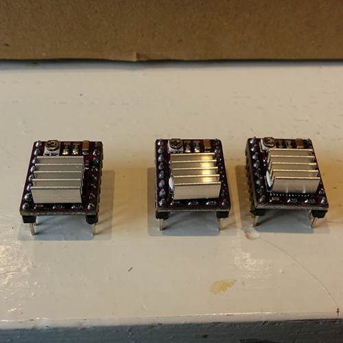
As these things can get quite hot, we added a heatsink to each board.
To get started I followed this tutorial.
As described in this tutorial, there are pins underneath the DRV8825 that need to be connected to determine the precision of microsteps.
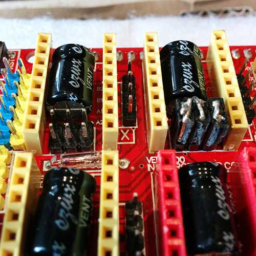
Because we didn’t have the right jumper for this, we took female header pins and folded and soldered the legs together.
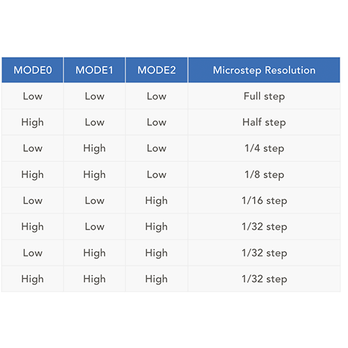
I followed this schematic to determine the configuration for the most precision, which meant connecting all sets of pins in the vertical direction.
The next step was finding a suitable power supply for the motors, and working out how much current they draw. To do this, I ran this simple sketch on the Arduino Uno with the CNC shield, DRC8825’s and stepper motors attached.
#define EN        8

//Direction pin
#define X_DIR     5
#define Y_DIR     6
#define Z_DIR     7

//Step pin
#define X_STP     2
#define Y_STP     3
#define Z_STP     4


//DRV8825
int delayTime=30; //Delay between each pause (uS)
int stps=6400;// Steps to move


void step(boolean dir, byte dirPin, byte stepperPin, int steps)

{

  digitalWrite(dirPin, dir);

  delay(100);

  for (int i = 0; i < steps; i++) {

    digitalWrite(stepperPin, HIGH);

    delayMicroseconds(delayTime);

    digitalWrite(stepperPin, LOW);

    delayMicroseconds(delayTime);

  }

}

void setup(){

  pinMode(X_DIR, OUTPUT); pinMode(X_STP, OUTPUT);

  pinMode(Y_DIR, OUTPUT); pinMode(Y_STP, OUTPUT);

  pinMode(Z_DIR, OUTPUT); pinMode(Z_STP, OUTPUT);

  pinMode(EN, OUTPUT);

  digitalWrite(EN, LOW);

}

void loop(){

  step(false, X_DIR, X_STP, stps); //X, Clockwise
  step(false, Y_DIR, Y_STP, stps); //Y, Clockwise
  step(false, Z_DIR, Z_STP, stps); //Z, Clockwise

  delay(100);

  step(true, X_DIR, X_STP, stps); //X, Counterclockwise
  step(true, Y_DIR, Y_STP, stps); //Y, Counterclockwise
  step(true, Z_DIR, Z_STP, stps); //X, Counterclockwise

  delay(100);

}
This simple sketch moves each motor a few steps forward and back, one at a time. This allowed us to check if each motor was functioning as it should, and how much current it draws.
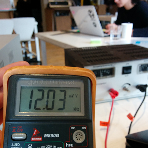
We powered the motors with a lab power supply, which read that at 12 volt, one motor drew 620mA. The power supply is rated at 3A, so some quick math led me to believe that 3 x 620mA = 1.86A which I thought the power supply would therefore be totally fine to handle.
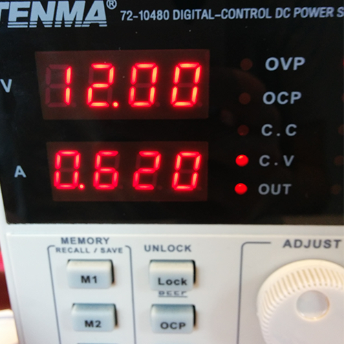
This was not the case, as soon as I powered two motors at the same time the power supply would fail. The reason for this is that when a motor first powers on, it draws A LOT of current, a lot more than when it is already running, so this spike in current draw from two motors at the same time appeared to be over 3A causing the power supply to fail. It is hard to see this problem as the spike happens so fast that the display on the power supply can’t even catch up and display it properly. The solution was to switch to a different power supply that is rated at 8A which worked well at 12 volt.
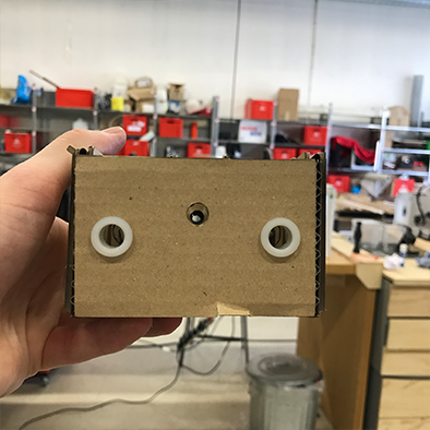
HOMING
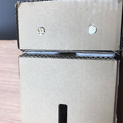
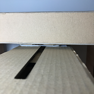
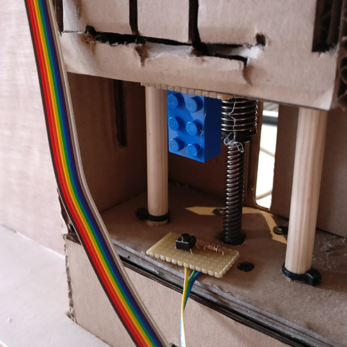
To ensure that the machine knows it’s position after a path and always starts at the same point, we added buttons to each stage that tell the machine where it is when pressed.
The button you see here gets pressed by a LEGO brick to make sure there is a good connection between the button and the stage, as the cardboard is too flexible for these rigid buttons.
CODE
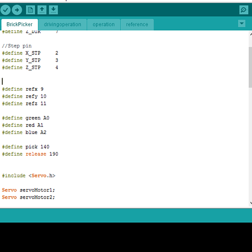
To keep the code clean and easy to adjust, I divided it up into three separate sketches, one main sketch called BrickPicker.ino, operation.ino and reference.ino. All three files can be downloaded at the bottom of the page. When using this sketch, make sure to put them all in the same folder.
The first sketch, BrickPicker.ino has the job of defining all the variables and laying the foundation basically for everything else to work like including the servo library etc.
The other main function of this sketch is to wait for a button to be pressed, triggering a set of commands in the operation sketch.
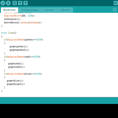
Once a button is pressed, the operation sketch is triggered, first the machine will calibrate using the reference sketch, then the path in the operation sketch is followed.
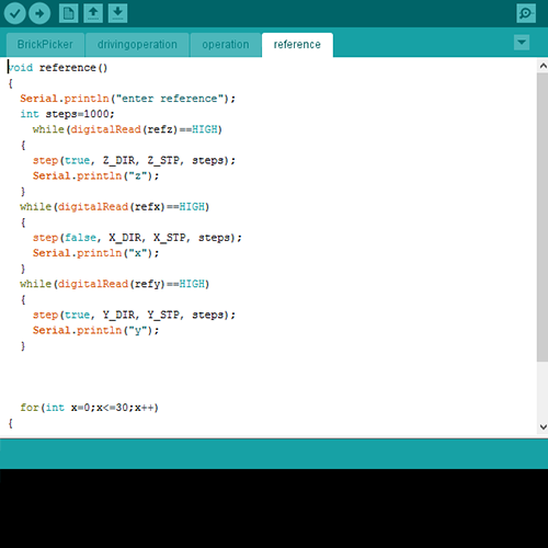
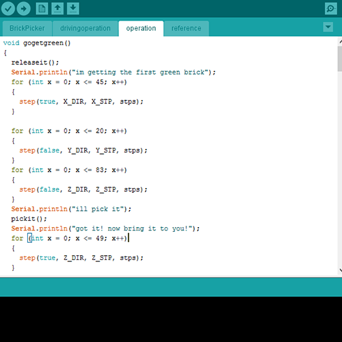
After an operation is complete, the machine will start reading the button states again and waits for a new command.
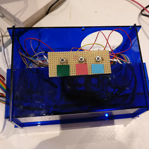
At the end we realised how many cables we do have so we decide to make a control box where to place them. It contains the cables but also there are three bottons or switches. This bottons are the ones that the user will interact with to specify what color wants to have. It is one bottons per each color: blue, red and green.
We have designed the box with Illiustrator and throught DXF format we have laser cut it. And the material is acrylic of 3mm.
bed DXF

gripper DXF
base DXF
control panel DXF
Arduino code 1

Arduino code 2
Arduino code 3