08 - embedded programming
1 - READING DATASHEET
As part of this week’s assignment I read the datasheet for the ATtiny44 and for the Atmega328 because I wanted to make my own Fabduino.
The datasheet for the ATtiny 44 can be found
here
And the Atmega328 is
here
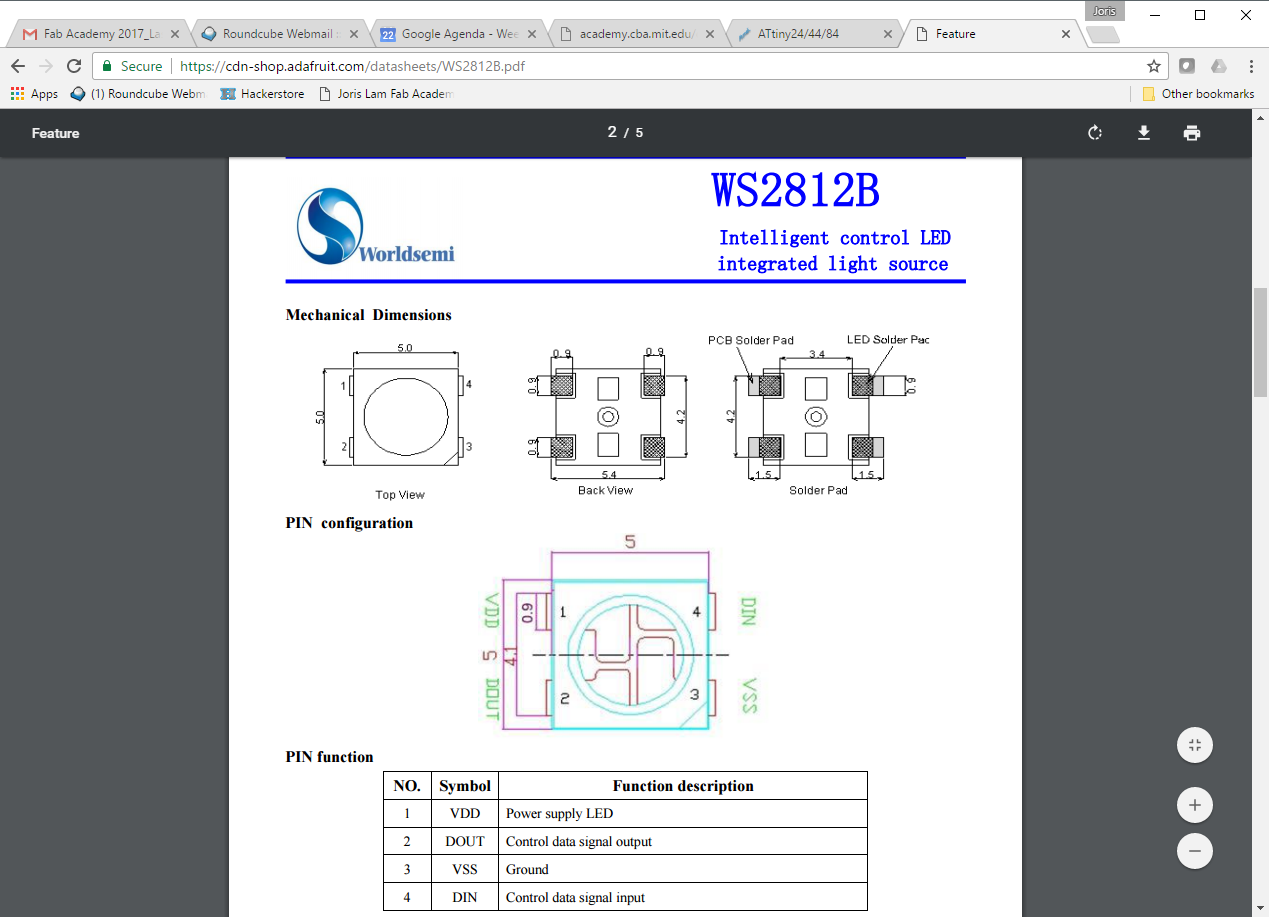
I also read the datasheet for the WS2812B LED with integrated driver which can be found
here
In the ATtiny44 datasheet I found these pages to be interesting and relevant:
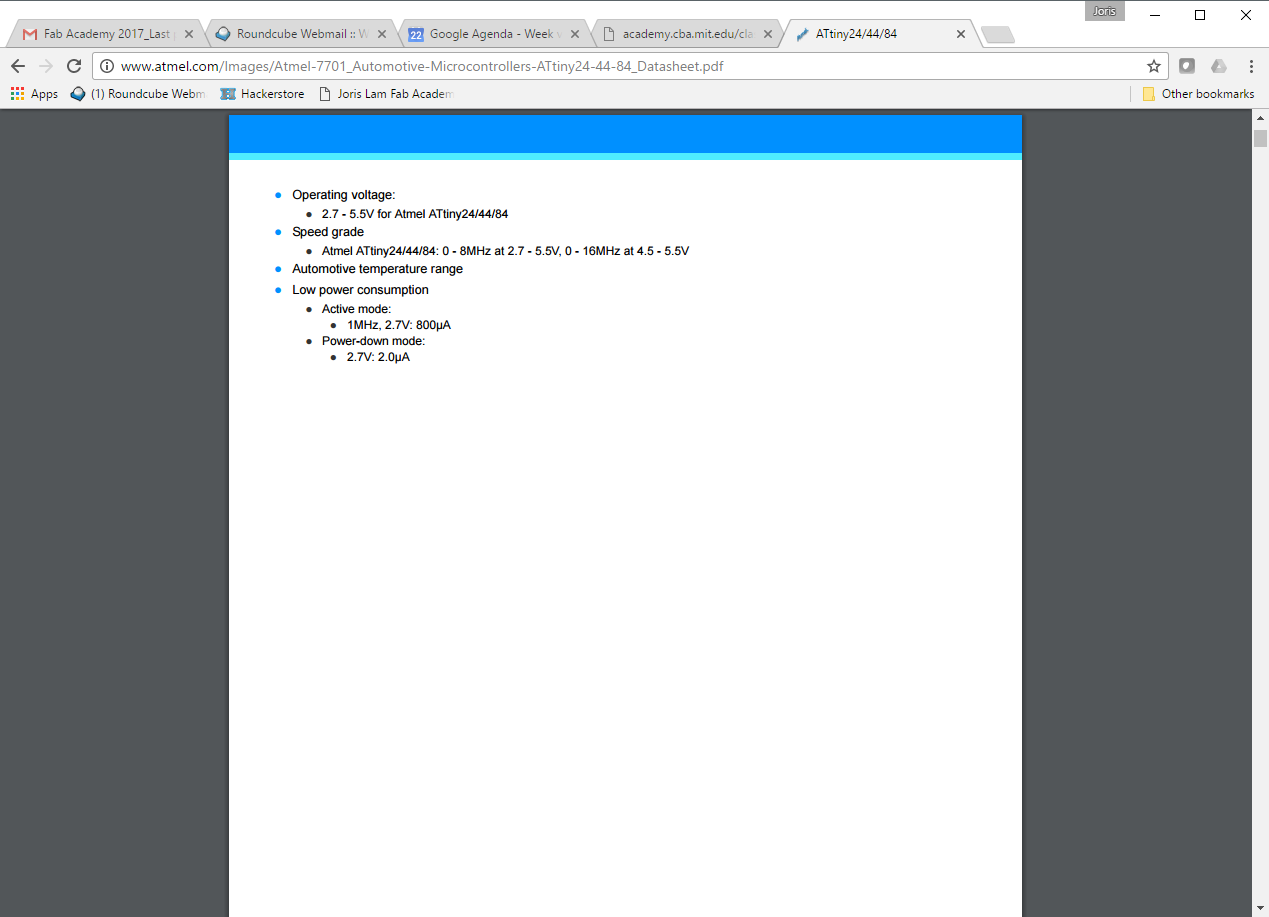
01 - operating voltage and speed grade, this tells you with which voltage you should supply the microcontroller and what speeds it can achieve:
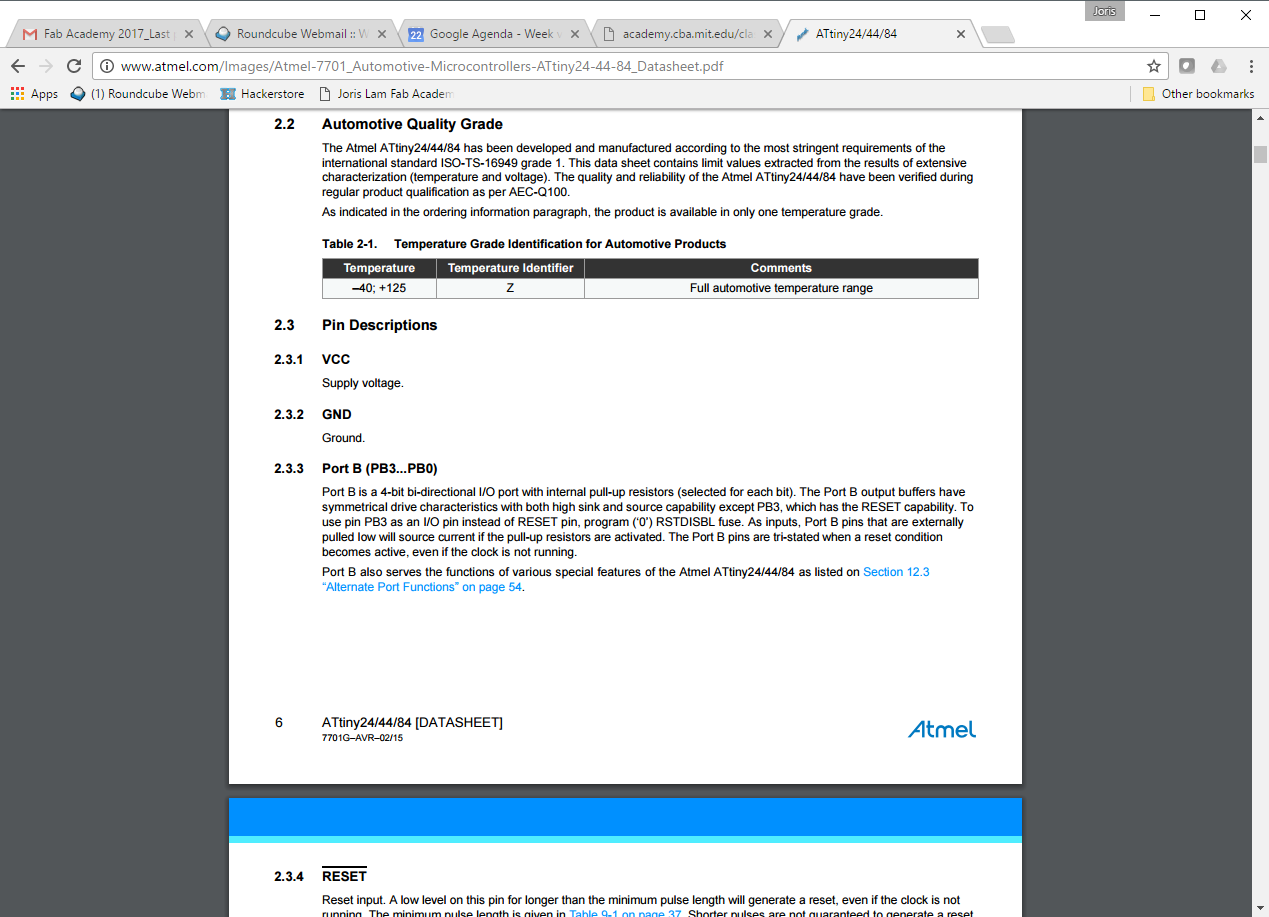
02 - temperature range and industry grade, apparently because this microcontroller can operate between -40 and +125 centigrade it is suitable for automotive applications. This is also good to know if you’re planning to use it outdoors like I am with sensors.
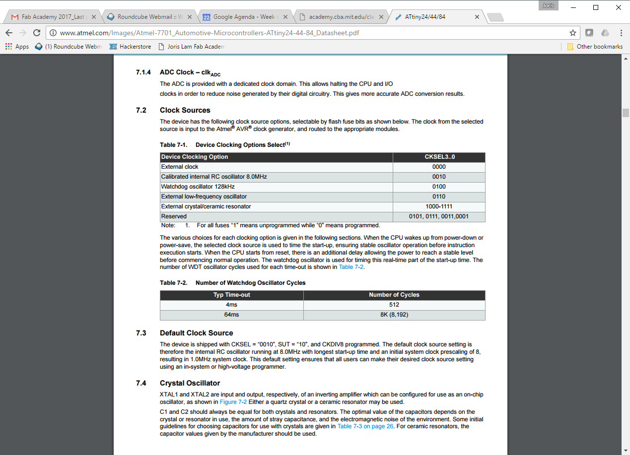
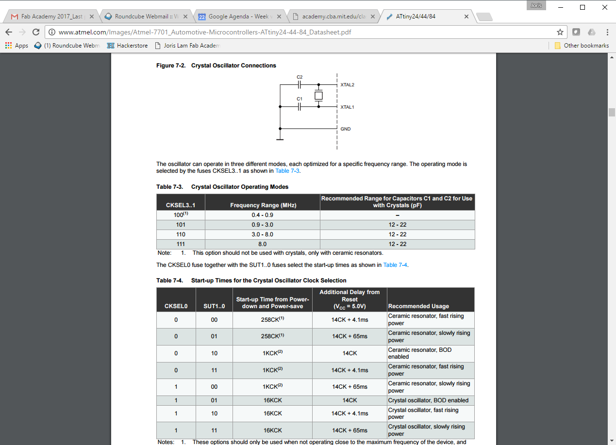
03 - the clock is very important to get right, because without the right configuration communication and timing will be off.
04 - this page shows how an oscillator or resonator should be connected.
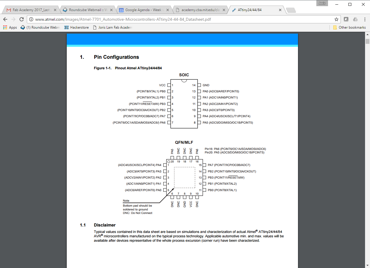
05 - pin configurations are also extremely important when you’re designing the schematics and layout for a board.
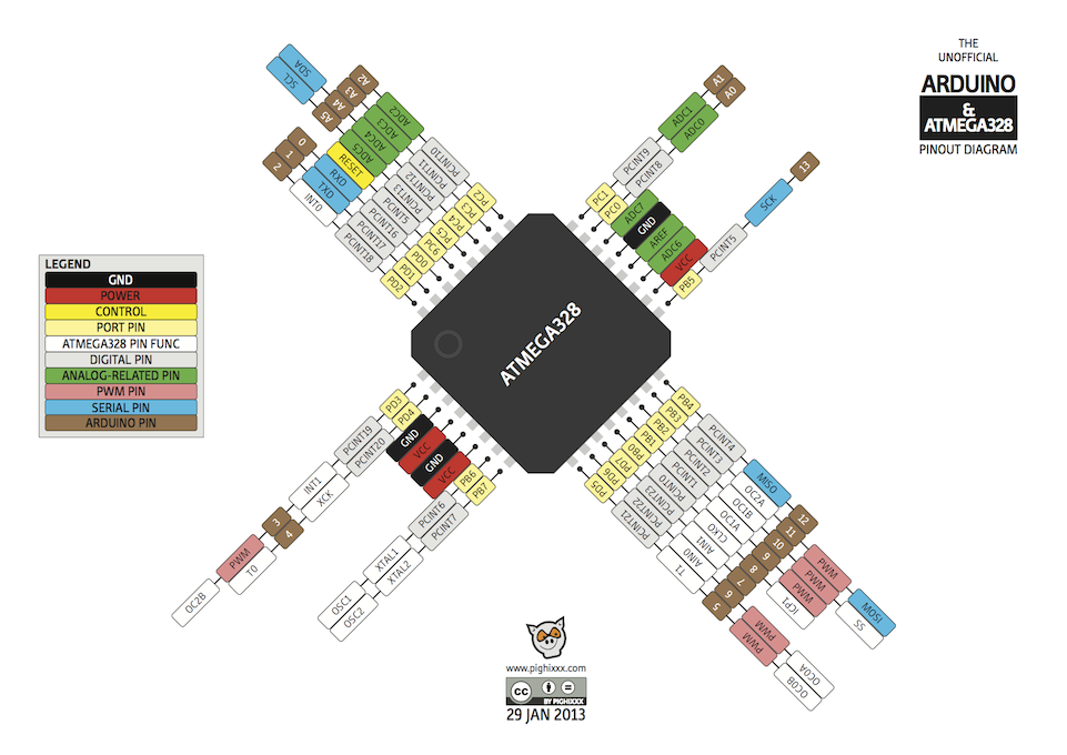
When programming it, this visual representation also helped me a lot because it is a little bit more clear at one glance than the datasheet.
To work out the orientation of the Neopixel I looked at the datasheet for the WS2312B LED which is the name of the component. The most important thing in this datasheet is the orientation of the pads.
2 - PROGRAMMING
First I programmed my hello world echo board with various functions for the input and output(button, LED) using the Arduino IDE. I did this using the programmer I made and programmed in week 4
Before I could upload sketches to it, I had to burn the bootloader onto it, I did this in week 6, and you can read the steps here: http://archive.fabacademy.org/archives/2017/fablabamsterdam/students/60/06electronicsdesign.html
I burnt the bootloader using a Mac, but since my Windows is my main machine I followed these steps to make my Windows ready for programming AVR: http://fab.cba.mit.edu/classes/863.16/doc/projects/ftsmin/windows_avr.html
Now I have a hello world echo board with a bootloader and my Windows up and running to program it. I made three sketches in Arduino IDE. You can find all the sketches at the bottom of this page to download.
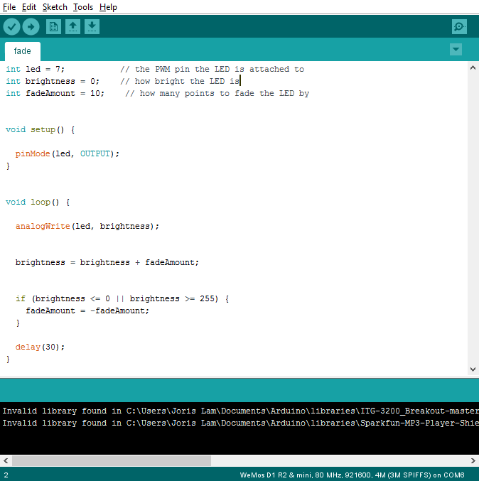
1 - fade
LED fades up and down
code breakdown
The first part of the code sets some integers, which tell which pin the LED is connected to, sets a brightness and a fade amount.
In the setup I declared that the LED is an output.
In the loop, I start an analogWrite, this means that I'm using the PWM function of that pin, which allows me to fade the LED.
PWM is not really fading in terms of giving more or less voltage, instead it just switches the pin on or of at 5volts extremely fast so it appears to be less bright.
The brightness and fadeAmount make the LED look like it is pulsating, the brightness will be between 0 and 255 which is the maximum, and the brightness is determined by the fade amount.
Change the fadeAmount and you change the pace of the fading, change the brightness between 0 and 255 and you control what the brightness range is.
2 - button fade
LED fades up and down when button is pressed
code breakdown
In the first part of the code I declared various integers, the pin to which the LED is connected, the brightness, fadeamount, the pin to which the button is connected and a standard buttonState of 0.
In the setup I state that the LED is an output and the button is an input.
The loop then reads the state of the buttonpin via a digitalRead command.
Then I introduce an if/else statement, saying that if the button button is pressed the LED should fade.
If the button is not pressed, which is the else situation, the LED is set to low and is off.

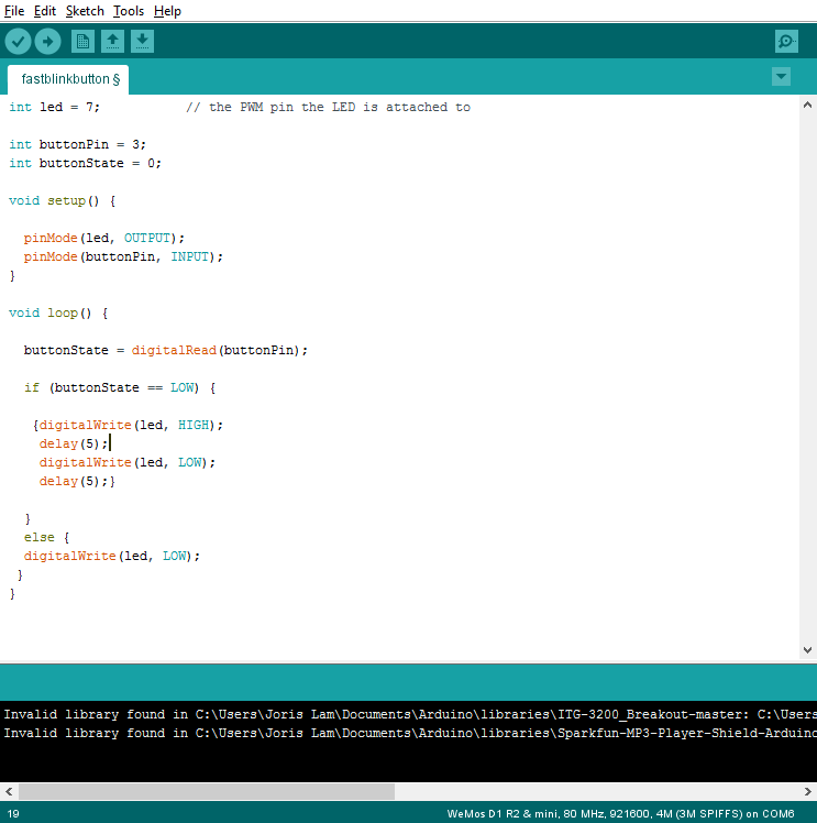
3 - button blink
LED blinks when button is pressed
code breakdown
This code is very similar to the button fade code above, the big difference is that the LED isn't being faded, so there is no PWM involved and instead of an analogWrite command there is only a digitalWrite command.
To control the speed of the blinking you can change the delay between the digitalWrite high and low.
3 - C
To upload the pre-written C code, I first downloaded these files from the class schedule:
C code
make file
One is the C code, and the other the make file.
I put them in together in a folder on my pc, and from that folder I used GIT bash.
Then I followed this tutorial and typed the following commands in the bash window after connecting the board using the ISP:
tutorial
make -f hello.ftdi.44.echo.c.make
make -f hello.ftdi44.echo.c.make program-usbtiny-fuses
note that for this second step, Mac users need to add ‘sudo’ before this command
make -f hello.ftdi.44.echo.c.make program-usbtiny
again Mac users should include sudo first
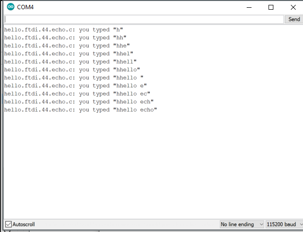
If all went well, you should get the following text in your bash window:
avrdude done. Thank you.
Now using an FTDI cable, you can connect the board to a PC and in Arduino click the serial monitor. The board now repeats every letter you type.
4 - FINAL PROJECT UPDATE
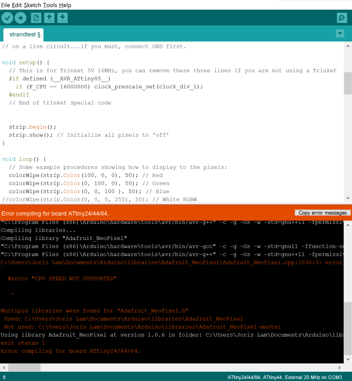
To tie this week’s assignment into my final project I decided to start building something out of LEGO that could hold a sensor and display data through LEDs. I build a black cube with a transparent strip which holds neopixels behind it. To see if this gave the desired result I used an Arduino nano clone and the standard strandtest that comes with the Neopixel library. It looks like this:
I wanted to program the hello world echo board to drive the neopixels but unfortunately support for these LEDs only starts from the ATtiny85 onwards, so my attempt to load the code onto the board failed.
So I decided to make a new board with the ATmega328.
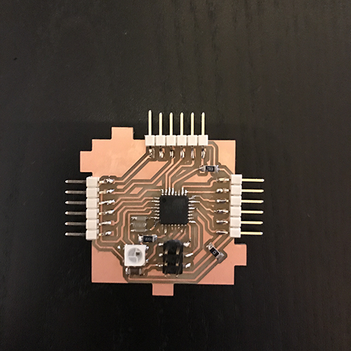
I designed a board part based on the Fabkit, part based on my requirements for my final project, which are quite similar. Because I want to include neopixels natively in my final project I designed a neopixel to be mounted on the board.
You can find the Eagle files and PNGs at the bottom of this page. Here is what it looks like:
I burnt the bootloader on it for the ‘Arduino Pro or Mini’ with a ATmega328 processor at 5volt and 16MHz external resonator. Originally I had a 20MHz on it, but this wasn’t in the options so I changed the resonator to 16MHz on the board. Another mistake I made was that I didn’t add a switch on the reset pin to pull it down while burning the bootloader, on my board reset is permanently pulled up to VCC. To fix this, during the burning of the bootloader, I manually connected the reset pin and ground with a jumperwire. It’s not a big issue since you only have to burn the bootloader once.
To my disappointment the on-board neopixel that I so carefully removed from an old strip doesn’t seem to work when I upload a basic example sketch. Perhaps the LED has been damaged before as I didn’t check it before I soldered it on there, or there is a timing problem.
I need to debug this more, the next step I will take to debug is to check if it works with an external neopixel that I connect to one of the IO pins. I will update this page as soon as I’ve done that.
To ensure that the board is in good working order I uploaded a simple blink sketch and that worked perfectly.
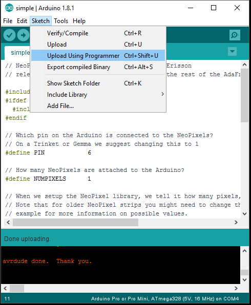
One last note that would have saved me a lot of frustration, when you upload a sketch in the Arduino IDE, you can usually click the arrow next to the checkmark, but with this board that didn’t work. Instead you should click ‘Upload Using Programmer’.
fade sketch

button fade sketch
button blink sketch
Eagle schematic

Eagle layout