04 - electronics production
This week we had to learn how to make a PCB(printed circuit board) in a way that doesn’t involve the usual chemical process of etching. A PCB is basically a series of electronic connections connecting various components. They can be flexible or wearable, but most common are rigid boards. To prototype electronics it is very useful to use a small CNC mill to make low quantity boards, which is what we learned this week.
The process of making a protoboard can be divided into these steps:
1 - design circuit board(this will be covered in another week)
2 - convert design to millable paths
3 - mill a copper clad
4 - solder SMD components
5 - program the programmer
01 - DESIGN OF CIRCUIT BOARD
Because electronics design will be covered in another week, we had to choose a pre-designed board from previous Fab Academy students. The boards are all ISP devices but all with slightly different designs. I chose Brian’s board as it is the most recent iteration and I like the simplistic look and design.
02 - CONVERT DESIGN TO MILLABLE PATH
To get the PCB design into a file the milling machine can read, it has to be converted to paths. I did this using fab mods, the browser based software that can drive a series of machines in the Fab Lab. The steps I took where the following:
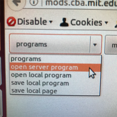
1 - on a computer running Linux, go to mods.cba.mit.edo from your browser

2 - under ‘programs’ choose ‘open server program
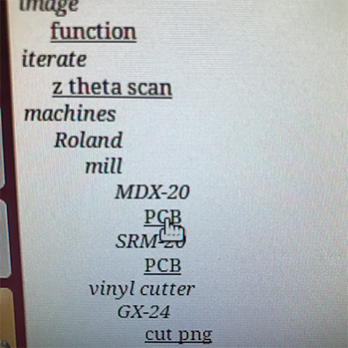
3 - under ‘machines’ choose Roland MDX-20 PCB. This depends ofcourse on the machine you’re using in your local lab.
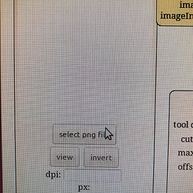
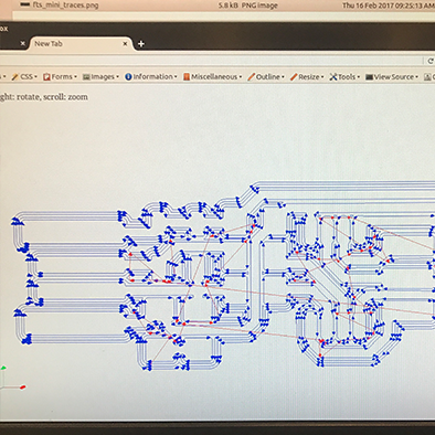
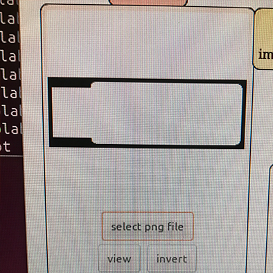
4 - in the first module, click ‘select PNG file.
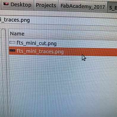
5 - start with the PNG file that has the traces, not the cutlines. In the case of the Brian board, this file is called ‘ft_mini_traces.png’
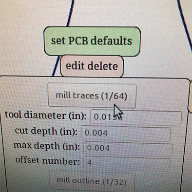
6 - in the ‘set PCB defaults’ module, click ‘mill traces’
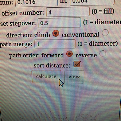
7 - in the next module, click calculate to get a preview of the toolpath
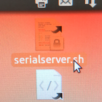
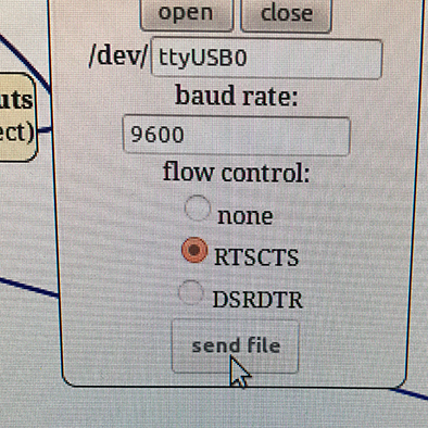
8 - now it’s time to send the path to the machine, to do this, you have to establish a connection between the mill and the computer. To do this, run the script ‘serialserver.sh’.
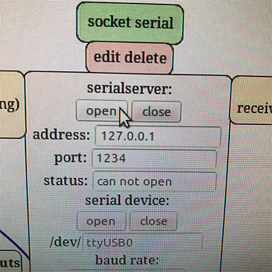
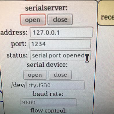
9 - in the ‘socket serial’ module, click on the ‘open’ button under the serialserver. If the connection is successful, the status will change to ‘serial port opened’.
10 - because the fab modules now talk to the mill, you can use the ‘Roland MDX-20 milling machine’ module to control and setup the machine.
11 - fill out values for X and Y and click ‘move to origin’ to move the head of the mill to the corresponding position. This position is the starting point for your milling work, so choose a place on the material that optimizes this and that will roughly fit your design.
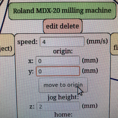
12 - the final step is clicking ‘send file’ in the final block, but don’t do this yet! First you need to calibrate the Z axis. This and all other steps required around the hardware rather than the software will be explained in the next set of steps.
03 - MILLING COPPER CLAD
In this set of steps I will describe the physical actions you need to perform to be able to mill a PCB out of a copper clad, given that you have all the software in place as mentioned above. I also ran into a problem that I will describe plus the solution.
The milling of a PCB consists of two phases, one is carving out the traces, in this step you do not want to cut through the entire material, but just through the top copper layer, and the second step is cutting out the PCB and making holes(if needed).
1 - prepare the cutting bed, by making sure you have a sacrificial layer, for instance an old PCB clad, as long as it’s even. To make sure you get the bed preparation right, take it out of the machine first. Do this by pressing the ‘view’ button first to allow easy access.
2 - clean the sacrificial layer with something we call ‘sticker solvent’ which eliminates old pieces of glue and grease.
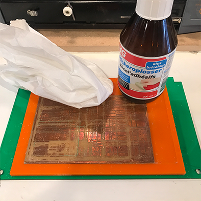
3 - add double sided tape to the sacrificial layer, enough to cover the full surface of the copper clad you will mill the PCB out of.
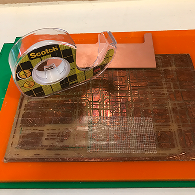
4 - place the copper clad on the sacrificial layer, pressing down firmly to assure a good grip between the two. Then place the bed back in the machine.
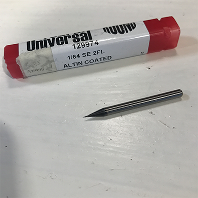
5 - install an end mill, for the traces you start with a 1/64 inch end mill. Unscrew the fastening screw on the mill head, insert the end mill and tighten. Make sure to put the end mill in as high as you can whilst still showing the point, this will be adjusted later.
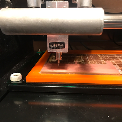
6 - take the machine out of ‘view’ mode by pressing the button on the machine, then bring the end mill to a starting position for the job. Do this by giving coordinates as described in step 11 of the previous list.
7 - calibrate the Z axis, the height of the end mill by using the ‘up’ and ‘down’ buttons on the machine. There are two things extremely important in this step, first of all, avoid at all cost smashing the end mill into the material, so never go all the way down to the material with the buttons. Instead, adjust the last part manually by holding the end mill when it is close to the material, loosening the screw and gently dropping it down until it touches the material. Twist is a few times to eliminate any dust that might have accumulated under the tip. The second important thing to keep in mind is something I did wrong in the beginning. When lowering the head using the buttons, you should not lower it all the way, because if you calibrate the machine with the head in the lowest position it can not go any lower when milling, resulting in traces that are not deep enough. Instead, find a balance between having the head at a height that allows it to go down quite a bit, but not too high as you want to limit the amount the end mill sticks out to a minimum to avoid vibration.
8 - now that the Z axis is calibrated and the milling head is in the right position you can close the cover of the machine and hit ‘send file’ in the fab modules and it will start.
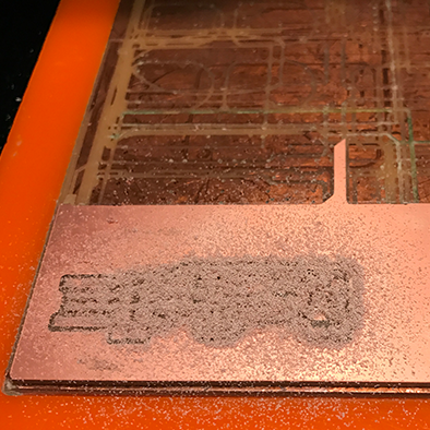
9 - If the traces are milled correctly you will see some dust on the copper clad and it should be clearly visible that there is no more copper where you milled traces.
10 - the next step is cutting out the board out of the copper clad, to do this replace the end mill with a 1/32 mill. To cut instead of trace, in the software, repeat steps 5 through 12, with the difference of choosing the cut PNG file instead of the traces and change the default settings to the ‘mill outline’ settings instead of the ‘mill traces’. After doing this repeat the machine steps 5 through 8.
11 - cut out a little left-over piece of copper using a sharp knife
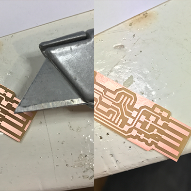
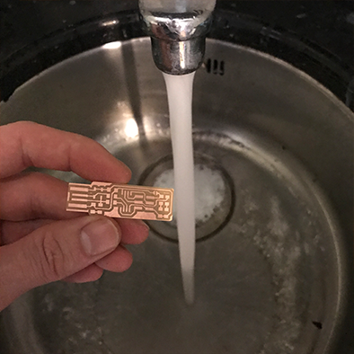
12 - take out the board and wash it in the sink with soap and water to eliminate finger grease and dust.
TROUBLE SHOOTING
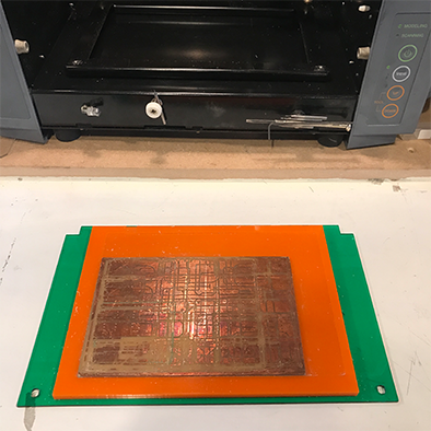
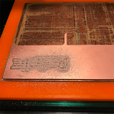
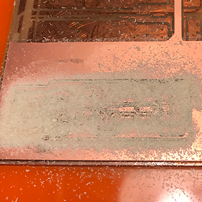
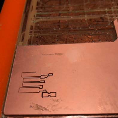
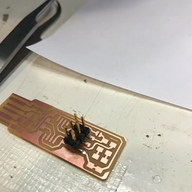
When I milled the traces at first, I did see some result on the copper, but I didn’t see dust accumulating on the board which is an indication that the mill didn’t go deep enough.
It looked like this
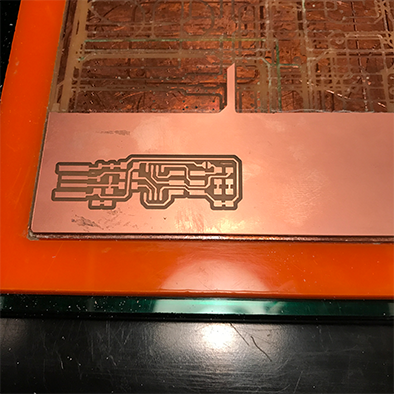
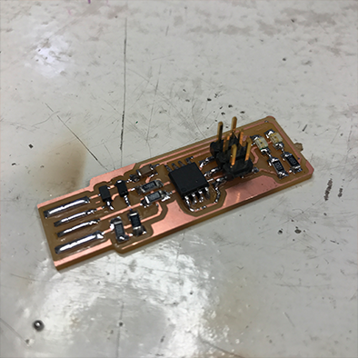
But it should look like this
The end mill didn’t go deep enough even though the settings seemed to be correct. At first I thought I didn’t calibrate the Z axis correct or that the clad was not evenly attached to the sacrificial layer, but after ruling all that out I found the source of the problem. When I calibrated the Z axis I lowered the head with the down button to it’s lowest point, and adjusted the end mill from that position. This means that the machine could barely go any lower from there and therefore could not make the required depth. The solution was recalibrating and leaving the head higher whilst lowering the end mill a little bit more so the machine has the space to make the depth required.
04 - SOLDER SMD COMPONENTS
Up next is soldering the SMD components to the board. To do this I used a Weller soldering iron with a very thin tip and tweezers to keep the components in place.
01 - collect required components and arrange them so you have easy access while soldering the board
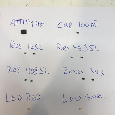
02 - check orientation of components, components that require a specific orientation always have some type of mark that makes it asymmetrical. This can be a small line, dot or color. When preparing your components, place them in the right orientation on a piece of paper and double check before soldering to prevent mistakes.
02 - when soldering SMD components, first apply some solder on one of the two pads for the component.
03 - take the component with tweezers in one hand, reheat the solder on the pad and when it’s molten, introduce the the component and let the solder cool down again fixing it in place.
04 - solder the other part of the component to the other part of the pad by touching both the component and the copper pad with the soldering iron and then introducing solder.
05 - I started with the pin headers first, as they would be hard to reach with the ATTiny already in place
06 - after soldering all the components I used a multimeter to check for short circuits, this means using the continuity function and checking if components that should not be connected do touch each other somehow. Look at the design sheet to determine which components should and should not touch, and then using the probes touch these components to check if you hear the beep or not.
07 - everything on my board looked fine so I did not have the immediate need for rework or debugging the board.
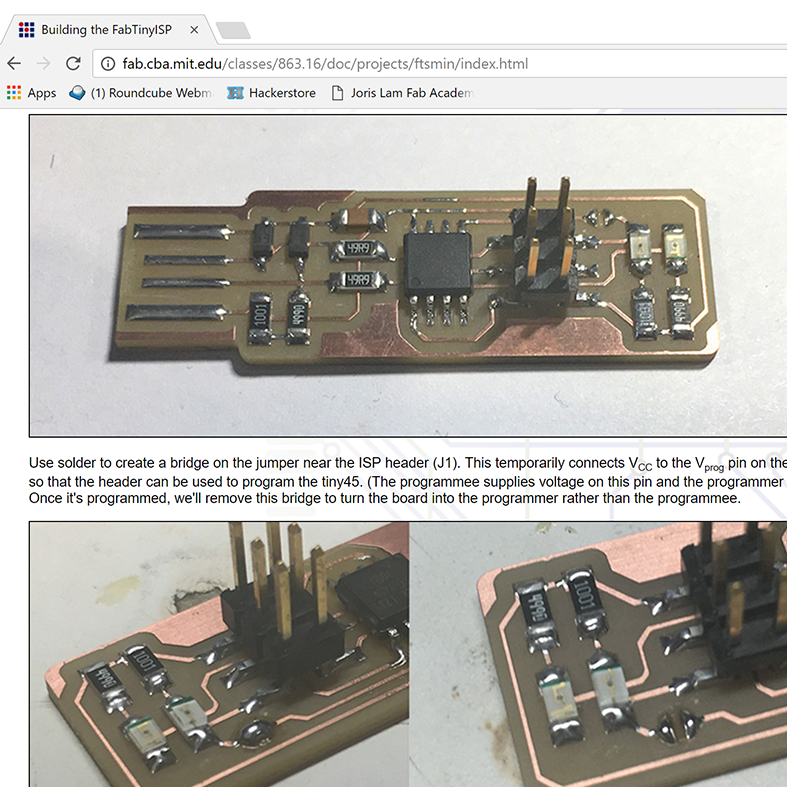
PROGRAMMING THE PROGRAMMER
To turn this board into a functional programmer, I followed the steps
on this page
using an Apple computer.
These are the steps I took to program the programmer:
1 - download and install CrossPack from this link: https://www.obdev.at/products/crosspack/index.html
2 - download the firmware source code from this link: http://fab.cba.mit.edu/classes/863.16/doc/projects/ftsmin/fts_firmware_bdm_v1.zip
3 - open terminal and 'cd' into the source code directory
4 - run 'make' and check if you then have a file called fts_firmware.hex
5 - connect another programmer to the new programmer, making sure the orientation is the same
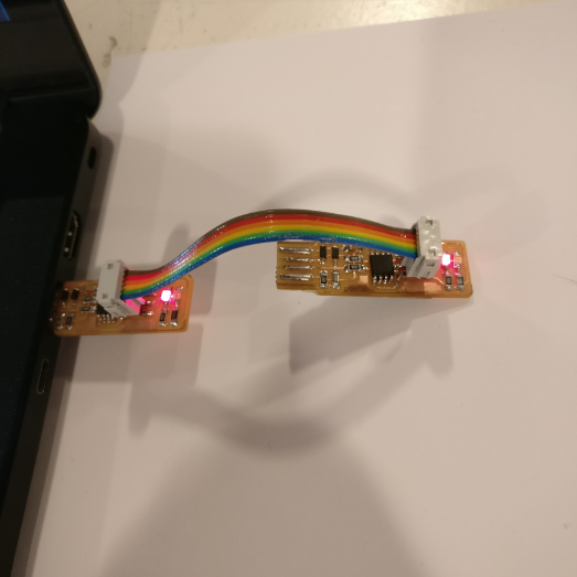
6 - then from the terminal, run 'make flash'
7 - if everything works, you can blow the reset fuse by running the 'make fuses' command
8 - before blowing the reset fuse, you have to make sure your computer sees the programmer as a USB device, to do this you go to the apple logo->about this mac->more information. When you click on the USB function on the left, the USBtiny should show up.
9 - to blow the reset fuse, reconnect your programmer to another programmer which is connected to USB, then run the 'rstdisbl' command
10 - officially you then need to remove the solder from the jumper, but in my case it only worked with the jumper still connected.
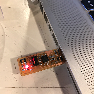
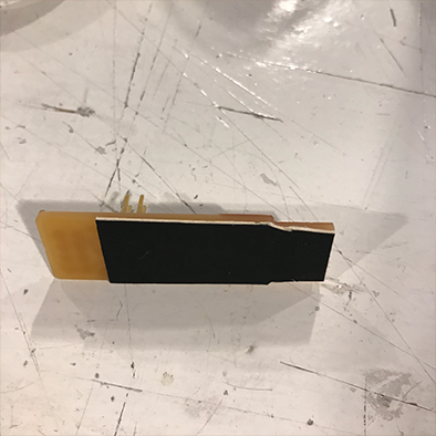
01 - the board is a little bit too thin to have a good connection with the USB port of a computer, that is why using some thick paper and double sided tape I made the board a bit thicker to ensure a good connection.
02 - in the step before blowing the reset fuse, you have to check if the computer recognizes the board in the USB port, to do this you go to the apple logo->about this mac->more information. When you click on the USB function on the left, the USBtiny should show up. At first it didn’t which could mean two things, the upload failed or the connection is bad. To rule out both, I re-did all the steps until I was absolutely sure there were no errors. Secondly I made the USB connector traces all the same height by filing them down.
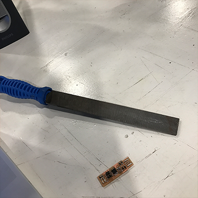
And now it showed up!