Week no. 15
Networking and Comunication :
- design and build a wired &/or wireless network connecting at least two processors
Hello I2C
For this assignment I decided to try to do the Hello I2C.
The I2C is a wired protocol that uses only two wires.
And not only two devices but also multiple devices can communicate each other.
To do that I used Neil's boards as a reference to draw my owns.
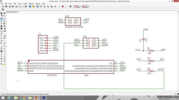
Eagle:
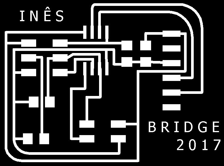
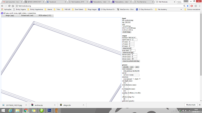
1. Bridge

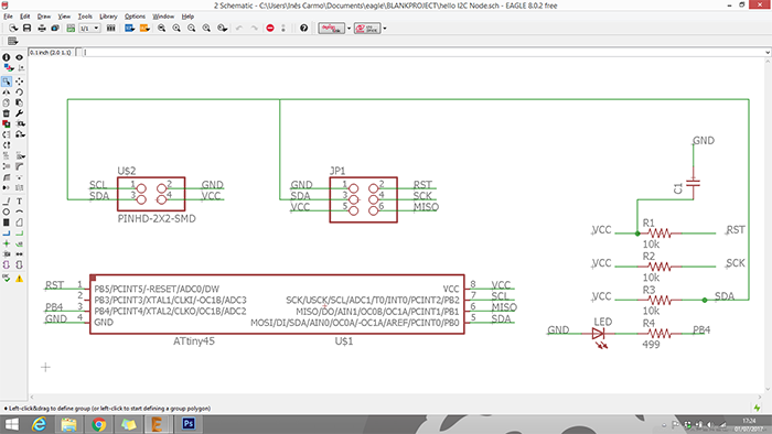
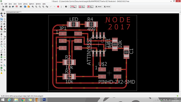
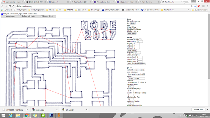
2. Node
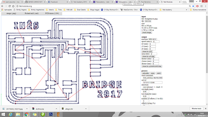
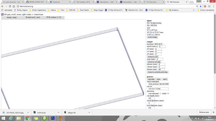
Now it's time to do the png's to the fabmodules for the code generation:
Bridge png.

Node png.

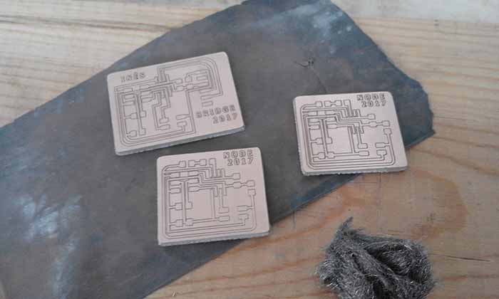
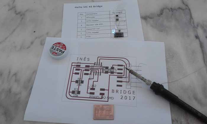
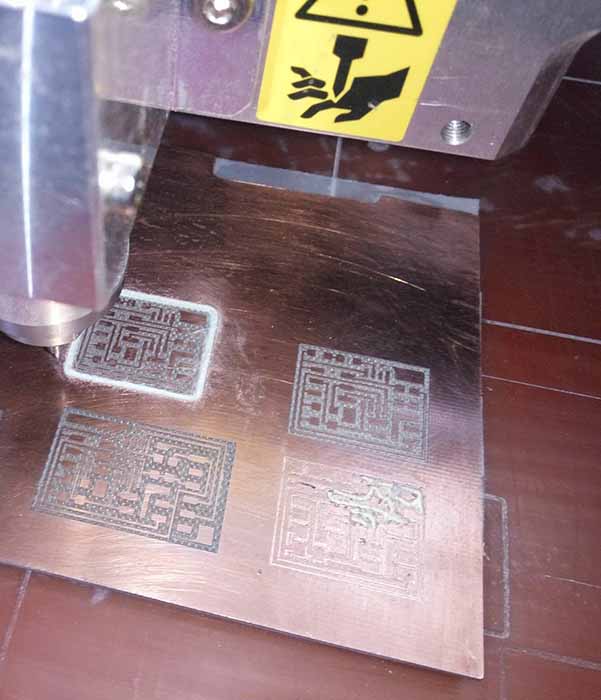
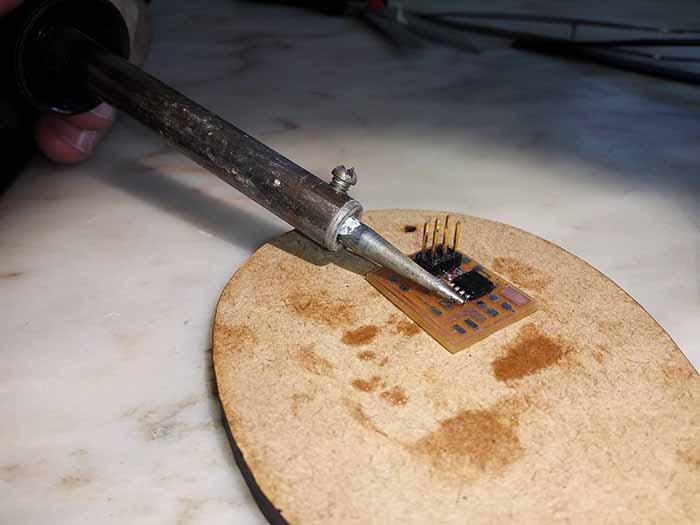
Milling and Stuffing
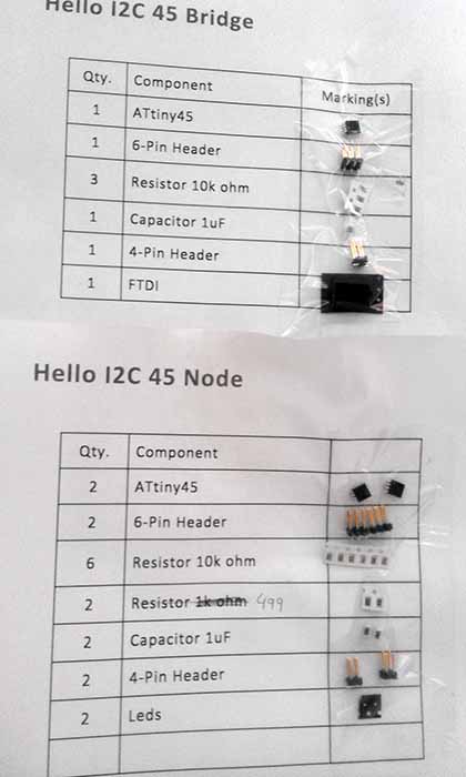
First step - Preparing the components:
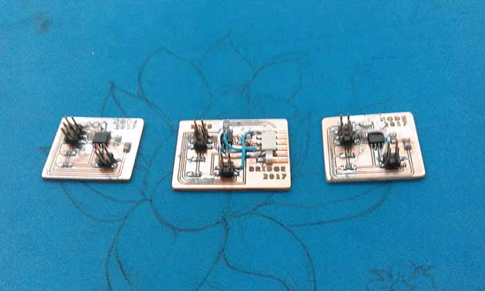
I set the components to make two nodes and one bridge:
Generating the code on the fabmodules:
Bridge:
Node:
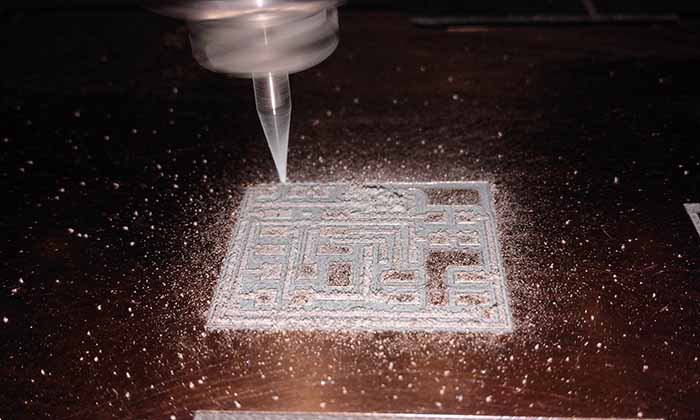
This time I had a little bit of a hard time milling the boards because I'm using an old v-cut mill
and the traces are getting rought but at the time i dont have another one.
Besides that I've been able to correct some of traces that were broken and the rest of the soldering.
Programing:
Before we proceed to test the I2C bridge and nodes, if using Arudino IDE we nedd to download this two libraries: - TinyWireM and TinyWireS.
The following simple code has been used for the communication for the bridge and one node.
After all this I only could connect to the bridge board,
besides the corrections that i made on the board, I could not connect the nodes.
I was unable to identify the root cause of the problem, so I decide to start again from the begining.
2nd Try
Because I had some problems with my board, I repeated them.
Using the same method as before.
But as I did not have much time until finishing the final evaluation and I did not want to take any risks and I made Neil's boards.
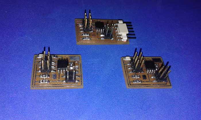
As before I made one the bridge board and two the node boards.
Milling:

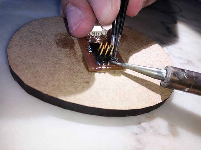
Stuffing:
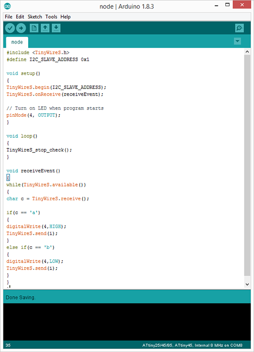
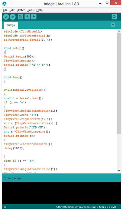
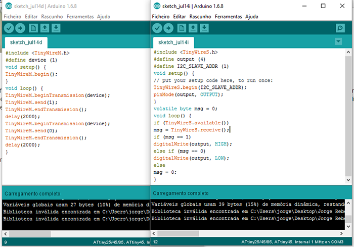
Programming - Understanding the code:
I used the same code as before, because I am pretty sure it's right.
For the node, i define this address as 0x1.
The program is written such that the bridge is communicating with the node,
and then send a 'a' to turn the led ON and 'b' to turn the led OFF. The node with addrees 1 will then respond by turning
ON and OFF the LED which correspond with the condition set with the message receive.
Although the code looks good as well as all the board connections, it did not work.
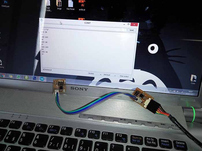
To overcome this, I converted the bridge code to the arduino, by replacing the TinyWireM with Wire.h:
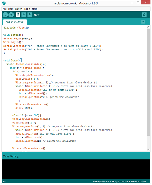
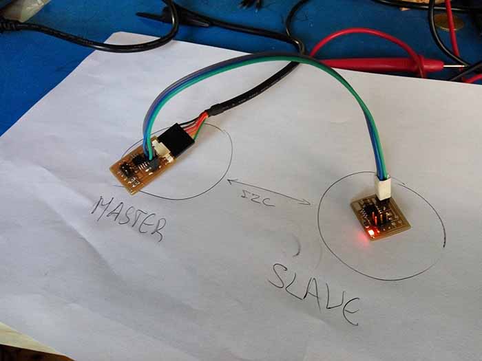
And it worked!
Communication between two processors was achieved using the I2C protocol!
~
One more try xD
In the research for a solution I found this previous fab academy student.
I dowloaded his code and tested it!
To summarize this week I share with you his thoughts about this solution and hope this may help someone else in the future:
"There are not many examples of using Attiny as master and slave. I find this topic a liitle dificult to understand.
The Attiny( both master and slave) if set at 1Mhz, the communication becomes very slow. It is only when I set the
slave to faster speed(at 8Mhz ) and the master at 1Mhz then everything began to work. I would like to explore further on this
like driving an I2C LCD , adding different devices like raspberry pi to the bus later." by Marc Ng
You can dowload all this weeks files here.