Exercise 16 - Networking and Communications
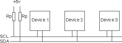
I would like to explore I2C communication. I read in http://playground.arduino.cc/Code/USIi2c that attiny 85 can be used as master or slave. The ATtiny85 (and it's cousins) does not have I2C (or SPI) "built in". Instead it has a Universal Serial Interface (USI) that can be used to facilitate I2C and SPI. There are not many simple to understand tutorial. Before I mill a new board, I need to understand more about the i2c communication. I wanted to try using Arduino Uno as the master and the attiny 85 board that i created during the output devices.
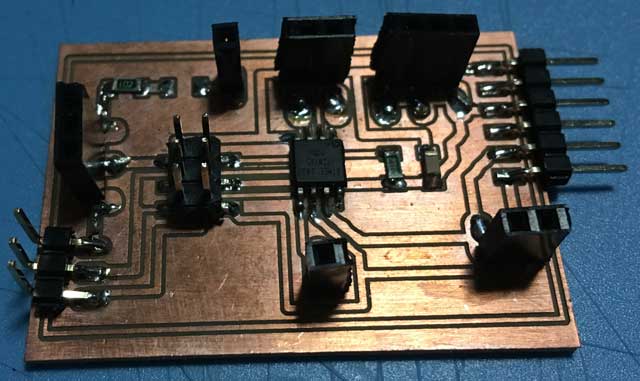
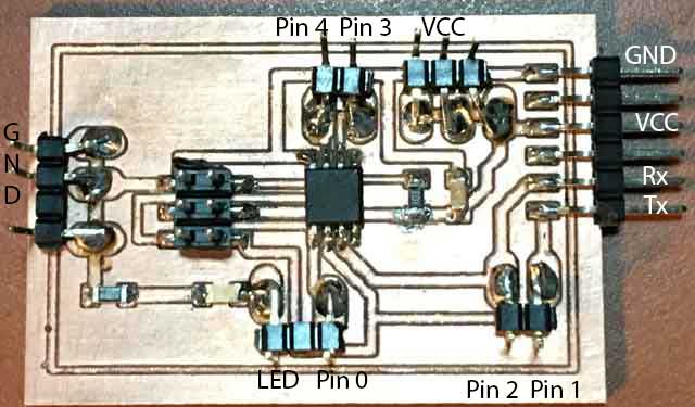
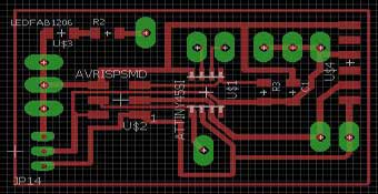
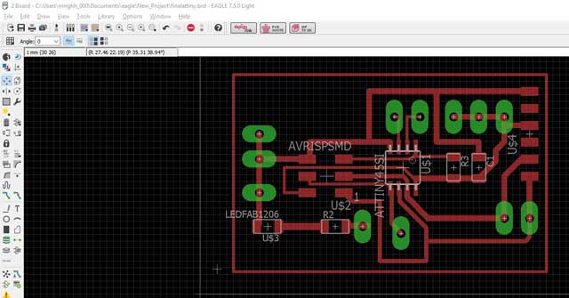
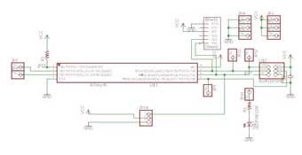
PCB Board
| ATtiny85 | ATtiny45 |
|---|---|
 |
 |
 |
 |
 |
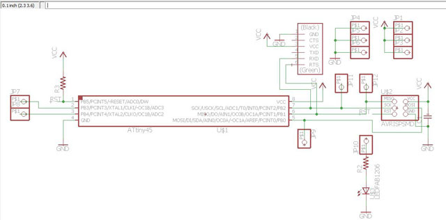 |
Pin configuration
And here is the SDA and SCL pins for various microcontrollers.| Controller | SDA | SCL |
|---|---|---|
| ATtiny85 | Pin 5 | Pin 7 |
| Arduino UNO | A4 | A5 |
I have no idea how to program it and I am going to use the example i found in The Wandering Engineer. I need to download ATtiny 85 i2c slave library and install.
For the Arduino UNO
#include <Wire.h>void setup()
{
Wire.begin(); // join i2c bus (address optional for master)
Serial.begin(9600); // start serial for output
}
void loop()
{
Wire.requestFrom(4, 1); // request 1 byte from slave device address 4
while(Wire.available()) // slave may send less than requested
{
int i = Wire.read(); // receive a byte as character
Serial.println(i); // print the character
}
delay(500);
}
For ATtiny 85
// Code for the ATtiny85#define I2C_SLAVE_ADDRESS 0x4 // Address of the slave
#include <TinyWireS.h >
int i=0;
void setup()
{
TinyWireS.begin(I2C_SLAVE_ADDRESS); // join i2c network
//TinyWireS.onReceive(receiveEvent); // not using this
TinyWireS.onRequest(requestEvent);
// Turn on LED when program starts
pinMode(1, OUTPUT);
digitalWrite(1, HIGH);
}
void loop()
{
// This needs to be here
TinyWireS_stop_check();
} // Gets called when the ATtiny receives an i2c request
void requestEvent()
{ TinyWireS.send(i);
i++;
}
Understanding the program
The master request data from slave and if data is available, it will display in the serial port. The slave will turn on the LED and when receive a request from host, the slave increment the value i by 1 each time (the value i was set initially at zero)
The Result
Testing 1 ATtiny 85 slave/ 1 ATtiny 45 master
Connection
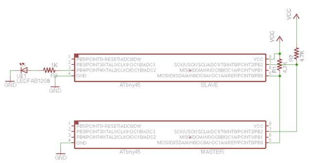
1. Burn the bootloader of the ATtiny 85. I am running the slave at internal clock 8Mhz
2. Burn the bootloader of the ATtiny 45. I am running at internal 1 Mhz
I am going to try a simple code.
Download TinyWireM
Download TinyWireS
Programming the master
#include#define device (1)
void setup() {
TinyWireM.begin();
}
void loop() {
TinyWireM.beginTransmission(device);
TinyWireM.send(1);
TinyWireM.endTransmission();
delay(2000);
TinyWireM.beginTransmission(device);
TinyWireM.send(0);
TinyWireM.endTransmission();
delay(2000);
}
The master is trying to talk to the slave which has the address 1. The master is sending a 1 and a 0 to the slave.
Programming the slave
#include#define output (4)
#define I2C_SLAVE_ADDR (1)
void setup() {
// put your setup code here, to run once:
TinyWireS.begin(I2C_SLAVE_ADDR);
pinMode(output, OUTPUT);
}
volatile byte msg = 0;
void loop() {
if (TinyWireS.available())
msg = TinyWireS.receive();
if (msg == 1)
digitalWrite(output, HIGH);
else if (msg == 0)
digitalWrite(output, LOW);
else
msg = 0;
}
The result
My thoughts
There are not many examples of using Attiny as master and slave. I find this topic a liitle dificult to understand. The Attiny( both master and slave) if set at 1Mhz, the communication becomes very slow. It is only when I set the slave to faster speed(at 8Mhz ) and the master at 1Mhz then everything began to work. I would like to explore further on this like driving an I2C LCD , adding different devices like raspberry pi to the bus later.
References:-
https://thewanderingengineer.com/2014/02/17/attiny-i2c-slave/
Download
Would you like to insert more style/elements?
Check the documentation of Bootstrap here.