Output devices
Week 10
Output Devices
Tasks
add an output device to a microcontroller board you've designed and program it to do something
RGB LED Board
After watching Neil's lesson and take a look at the options i had, i decided to make the RGB Light output Device, wich i'm going to use in my final project to illuminate my greenhouse interior, according to daylight's level.
This week's assignment is to built a output device, I choose RGB LED project. This light blinksin a single RGB mode.
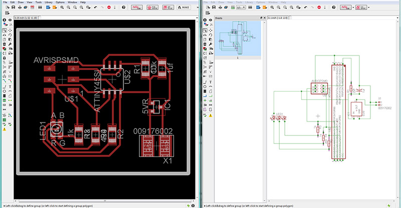
First I design the circuit in Eagle software. It contains ATtiny 45 one RGB LED three resistors, ISP connector and voltage regulators etc. I designed it in eagle and is shown below.
Board Production in Eagle
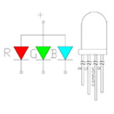
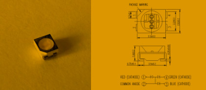
RGB LEDs consist of one red, one green, and one blue LED.
By independently attenuating each of the three, RGB LEDs are capable of producing a wide color range.
RGB LED Scheme
After completion of circuit design Mill in eagle, i cut the PCB with Modela MDX-40A. YOu can find the necessary steps for the fabrication and setup in the previous assignments.
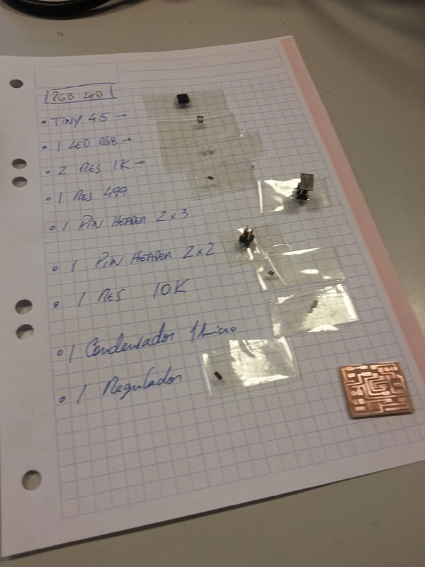
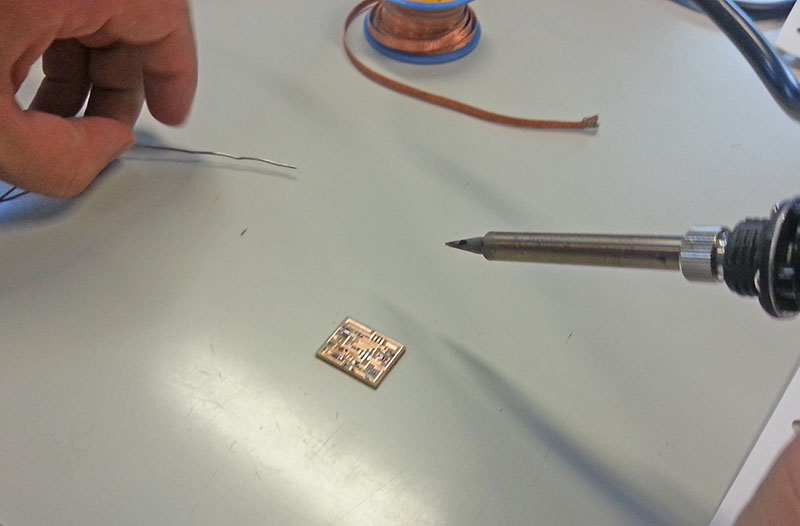
Colecting the components
Soldering the components
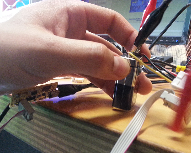
I had to verify all the solderings at the end because the board wasn't flashing properly, and found 2 weldings that weren't supposed to be connected. I connected a 9V battery to the board for auxiliar power.
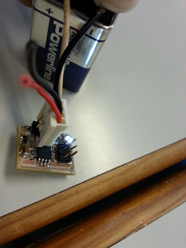
Connecting a 9V Battery
Testing the board
When all components were connected to my FabIsp i compiled the C code:
sudo make -f hello.RGB.45.make
and then
sudo make -f hello.RGB.45.make program-usbtiny
sudo make -f hello.RGB.45.make program-usbtiny
avr-objcopy -O ihex hello.RGB.45.out hello.RGB.45.c.hex;\
avr-size --mcu=attiny45 --format=avr hello.RGB.45.out
AVR Memory Usage
----------------
Device: attiny45
Program: 330 bytes (4.0% Full)
(.text + .data + .bootloader)
Data: 0 bytes (0.0% Full)
(.data + .bss + .noinit)
avrdude -p t45 -P usb -c usbtiny -U flash:w:hello.RGB.45.c.hex
avrdude: AVR device initialized and ready to accept instructions
Reading | ################################################## | 100% 0.00s
avrdude: Device signature = 0x1e930b
avrdude: NOTE: FLASH memory has been specified, an erase cycle will be performed
To disable this feature, specify the -D option.
avrdude: erasing chip
avrdude: reading input file "hello.RGB.45.c.hex"
avrdude: input file hello.RGB.45.c.hex auto detected as Intel Hex
avrdude: writing flash (330 bytes):
Writing | ################################################## | 100% 0.37s
avrdude: 330 bytes of flash written
avrdude: verifying flash memory against hello.RGB.45.c.hex:
avrdude: load data flash data from input file hello.RGB.45.c.hex:
avrdude: input file hello.RGB.45.c.hex auto detected as Intel Hex
avrdude: input file hello.RGB.45.c.hex contains 330 bytes
avrdude: reading on-chip flash data:
Reading | ################################################## | 100% 0.33s
avrdude: verifying ...
avrdude: 330 bytes of flash verified
avrdude: safemode: Fuses OK
avrdude done. Thank you.
This is my Final Board
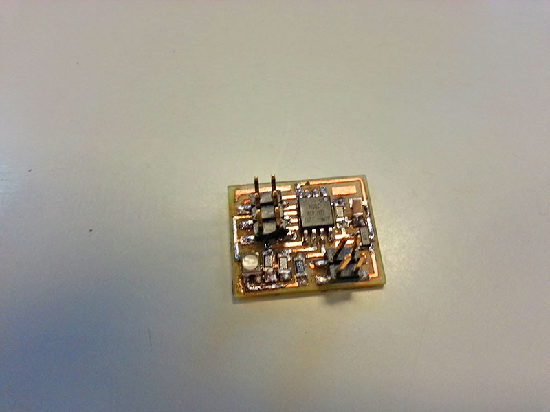
Everything went well. Work done! Here's my final video:
Video of the board flashing
My final project has some output devices, 1 ultrasonic humidifier and 2 fans, see in project development
All files