Computer-Controlled Machining
Make (anything) Something Big
The assignment for this week is to learn about computer-controlled machining.
See details here.
Object made with CNC
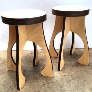
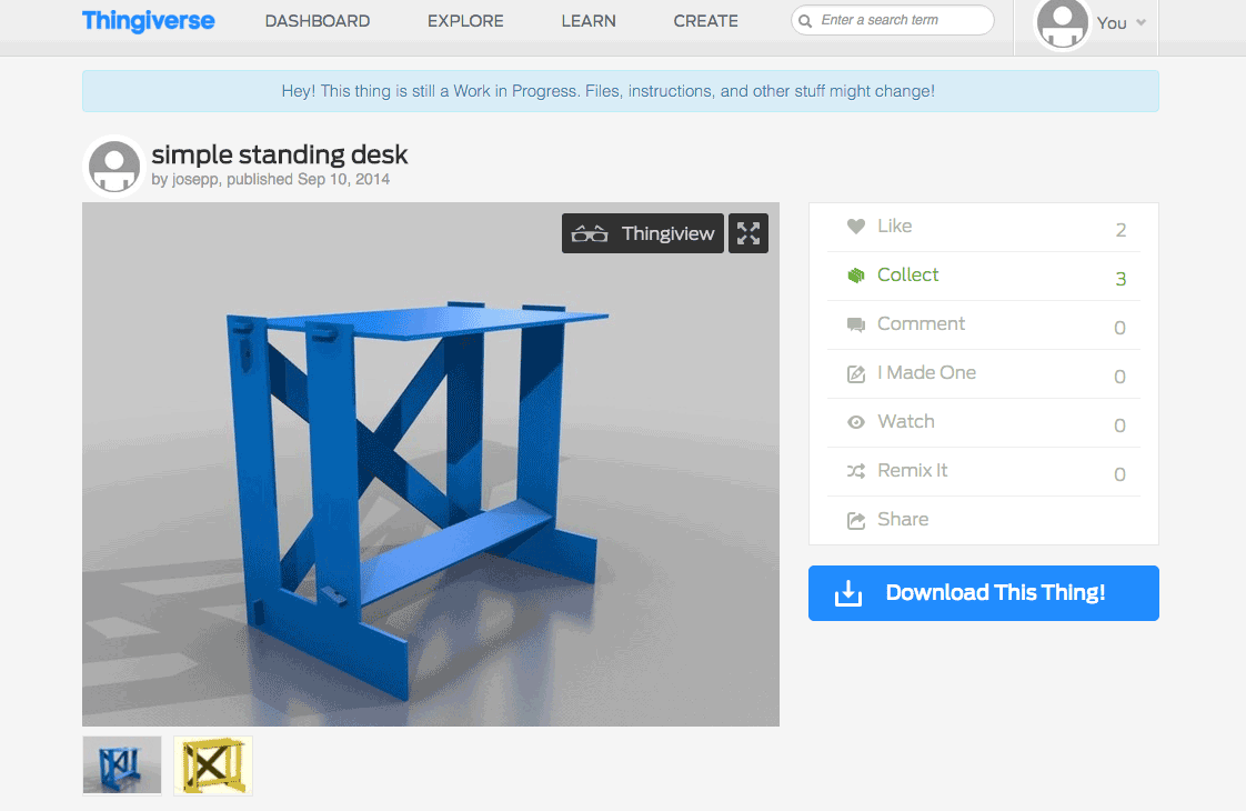
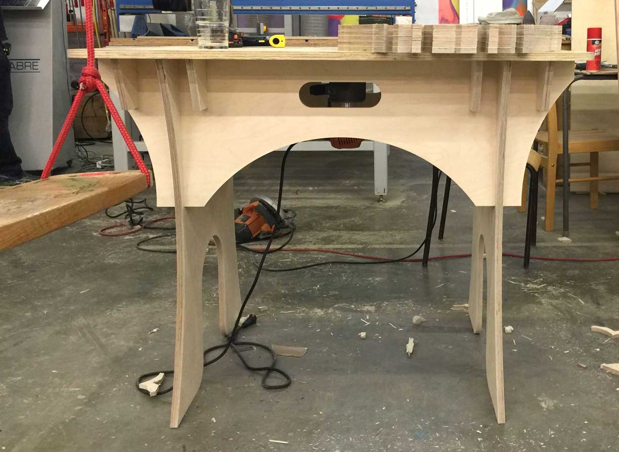
I started by looking on Pinterest, Instructable,Thingiverse and of course some student work some student work for inspiration. I saw a few examples I might modify and make that may be usefull such as this stool or table for a router or a CNC Maker Bench where I can download the original cut file here.
In the process, I learn about two more sites I did not know, CNC Zone Forum and Make CNC where we can download and buy CNC plans. Open Desk is a company that provides not only plans but connects us to local makers that can actuallly make the object for us. I met them last year in 2015 at the world MakerFaire in New York city.
Making a Stool
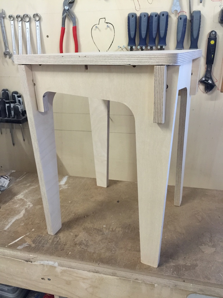
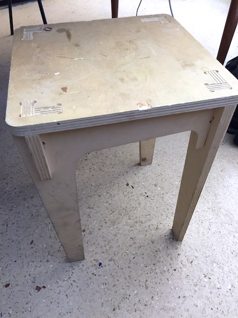 Since I have been to Woma, I have been sitting on a fairly simple stool, but surprisingly comffortable. I always wanted to create furniture with a CNC and this is a great opportunity to make one. The stool was first designed by Wao Team. Most CNC furnitures show purposly the joints. My excercices this week will be to modify the joints, to create à pocket, so that the design will hide the joints on top of the chair.
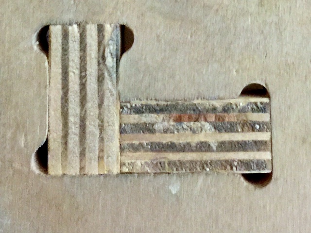
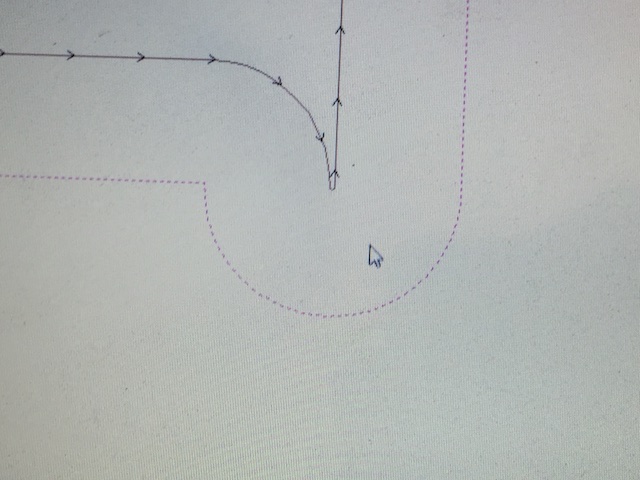
I noticed that this type of joints have extra hole on the corner. Clément Langelin, an architect and designer at Digfabstudio told me that the milling machine on the CNC may not produce a sharp 90 degree cut. Tthe joints explained below by Sean Michael Ragan on Make Magazine
Because of its very small cutting channel, a laser cutter can produce an inside corner with a sharp angle, whereas a rotary cutter using a physical tool is limited to inside corners rounded at the cutting tool’s radius:
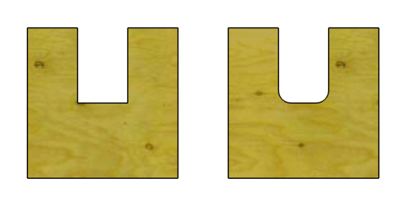
The laser-cut version, with its sharp 90 corners, is suitable for use in a simple edge-lap joint:
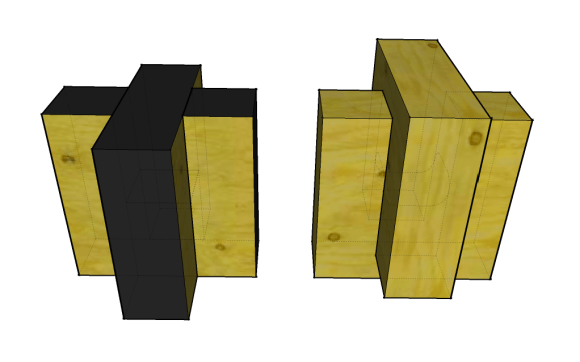
The router-cut version, however, doesn’t work. The radiused corners bump into each other and the part edges don’t line up. You can cut each slot a bit deeper, of course, and in some applications this may be OK, but doing so leaves a void in the center of the joint and concentrates stress on the radiused corners. A better solution is this:
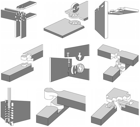
More examples of wood joints
Modifying the file in Rhino
The origianle file is in Rhino. I never used Rhino before so this is a big learning curve for me. I listen to a Dave Schultze tutorial online on Lynda.com. There are excercices files to follow the instructor and the tutorial is well done.
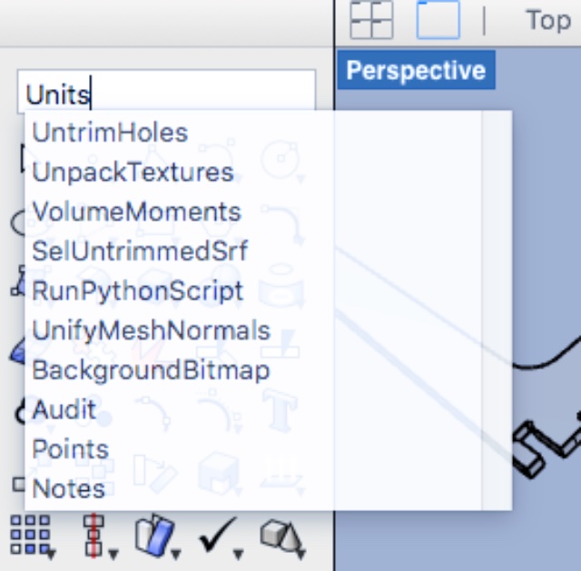
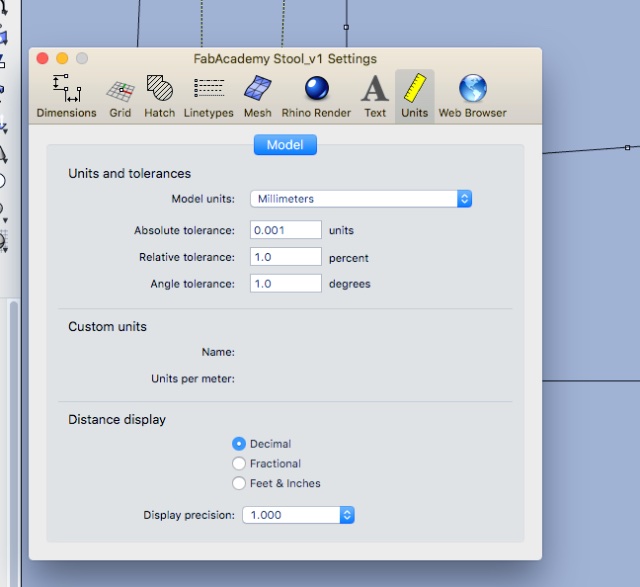
First thing I did was made sure what unit the file was set. In mm. The height of the plywood to be used is 18.
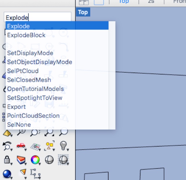
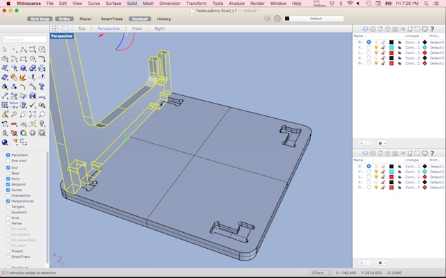
I selected the curve and used the command field to explode the cuve to be able to modify it.
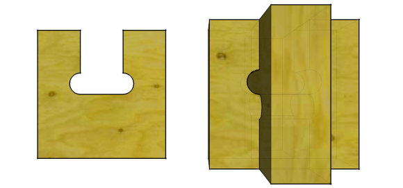
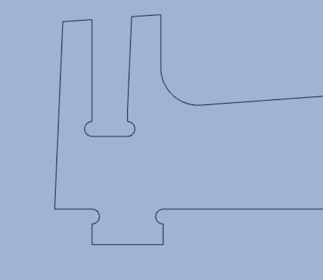
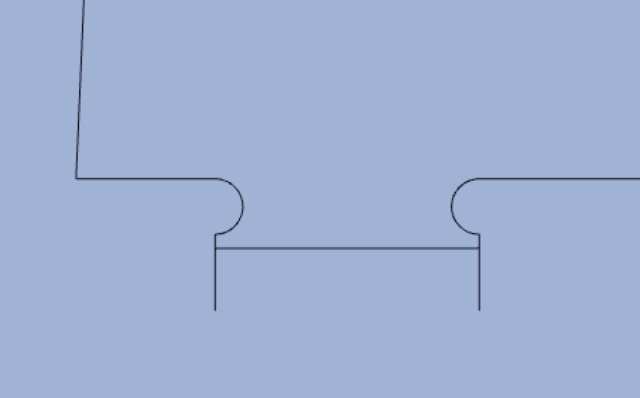
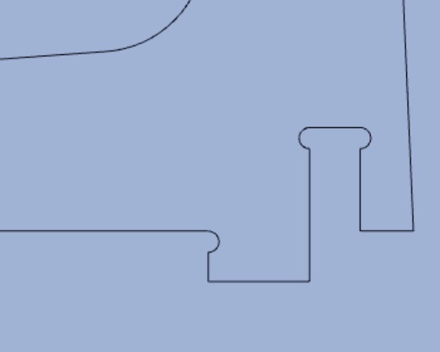
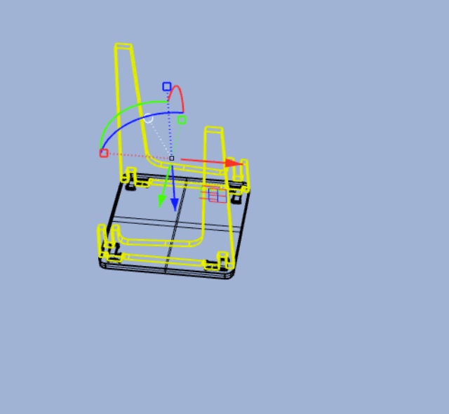
To hide the joints I would have to create a pocket on the top of the chair leaving 9mm of material and make the joint 9mm lower. Below is the image of one of the corner to be modified.
While moving the joints to 9mm, the joints became too small. So it was better to move the holes on the other edges and did the same thing on the other corners.
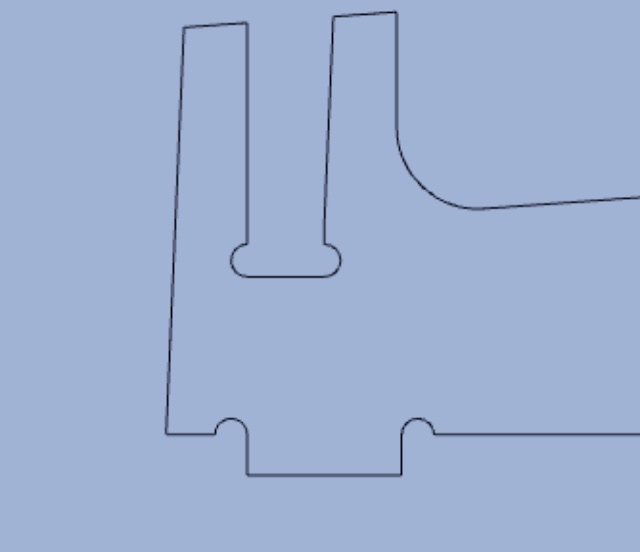
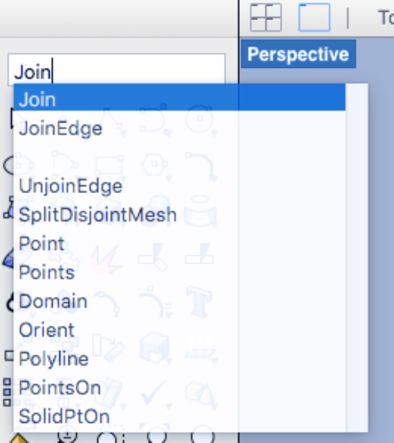
Making sure the lines are well joined I selected all the curves and joined them.
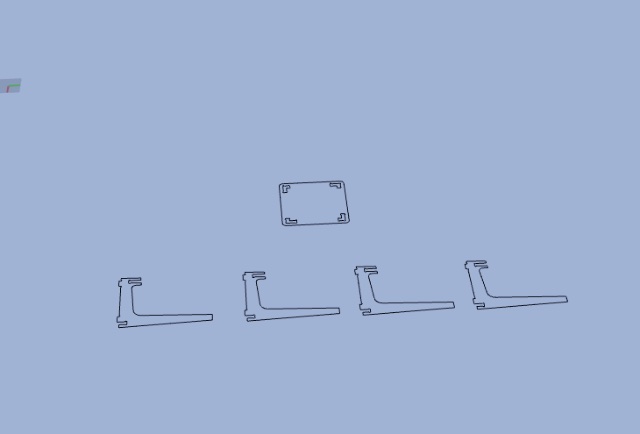
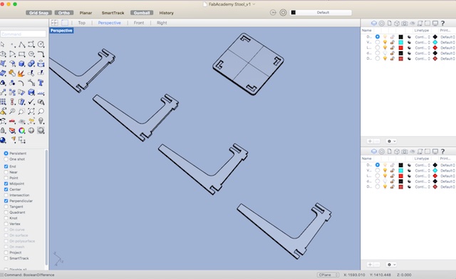
The four legs are the same so I copied the legs four time.
3D Modeling
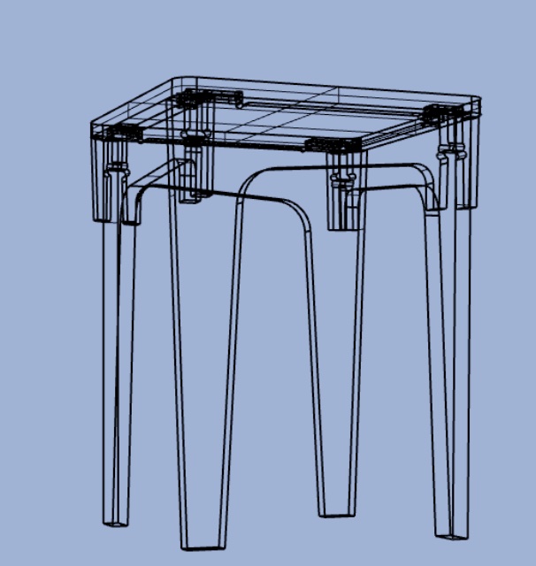
For the purpose of cutting the file on the CNC, I did not need the 3D modeling but wanted to make the excercice to create the 3D modeling. It also helps to see if all the joints are well alligned. Note that I kept a copy of the curves on the plane unextruded. The curves will later be use for generating the code for cutting on the CNC.
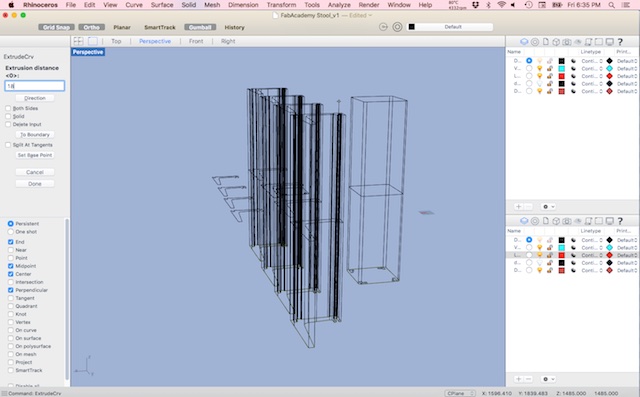
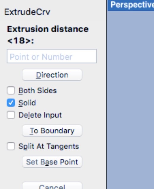
Typed in ExtrudeCrv in the command line and 18 for the size. Note that the solid field is enable. Otherwise it will create an extrude without the surface on top and bottom.
I typed in BooleanDifference to create the 9mm pocket.
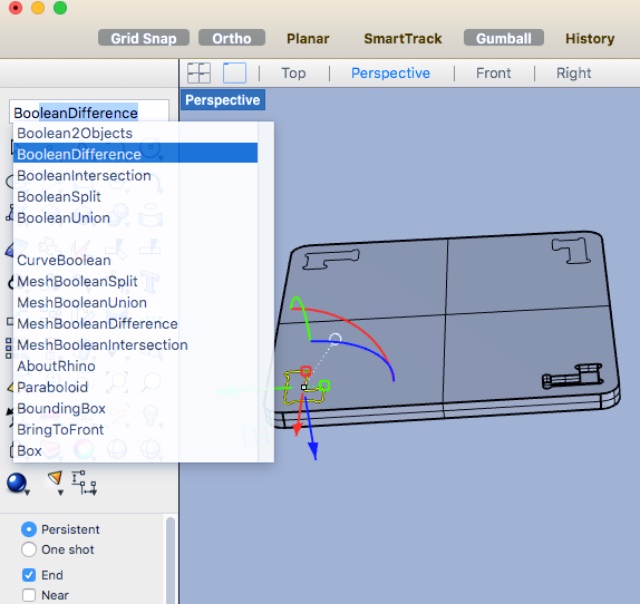
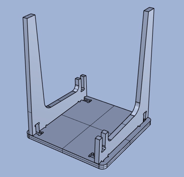
Here is the result
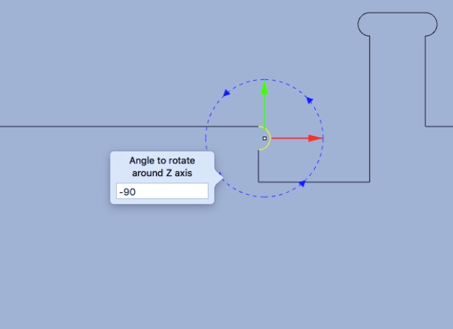
I rotate the legs 90 degrees and moved it by joinoing the right corner of the leg to the corner in the pocket. VERY USEFULL and easy to do. Note that the Gumball was selected to see the rotation. I can either use the Gumball or the command tool. I copied the piece and rotate it.
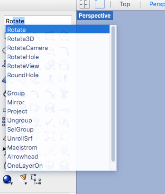
With two legs in place, I selected them, enter rotate by clicking ALT, this will duplicate the two legs and select the blue curve to rotate on the Z Axis.
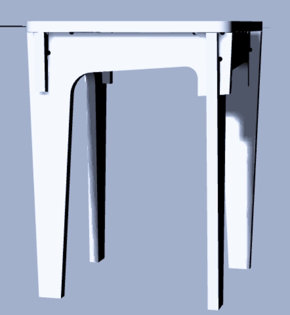
Voilà!
Exporting for vCarve
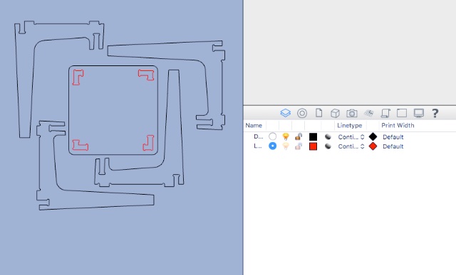
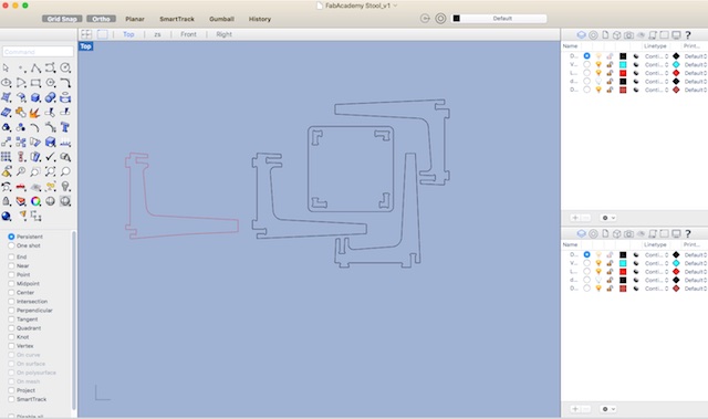
To export the file to vCarve to generate de gCode that will tell commands to the CNC. I separated the curve on two layers. One layer will do the cutting job and the second for carving the pockets.
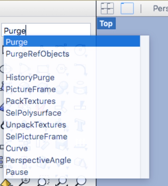
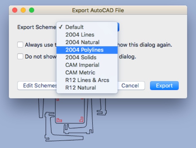
I used the purgecommand to delete the unnecessary layers and export the file in DXF format; choosing 2004 polylines.
Vcarve
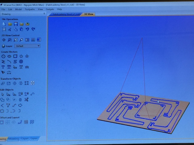
CNC machines require two different kinds of programs: one for controlling the machine, and one for generating g-code that the machine follows. I used Vcarve to create the gCode. I could have used the Fab Modules like I did with the PCB (fab ISP, Hello Board) in earliers weeks but vCarves is very easy to use and allowed me to generate tool paths, and previewed a 3D representation of the finished product. vCarve software is not free but it is well worthed. I heard there is a lighter version called Cut2D, but I never used it. At Woma and Makerspace North, we use vCarve. I later learned after trying to fit my stool design piece that there is a “nesting” function which finds the optimal arrangement to squeeze parts into the material to reduce waste, and automatic “tab placement,” which makes it easy to add small tabs to keep creations from slipping as your router cuts them out. Another feature is the “Estimated Machining Time” function, but users at Woma said that sometime they have to double the time. Other features are:
- colors can be added to each toolpath to allow customers to preview the finished product
- I can use a toolpath as guide in Rhino to see how it fits on a left over piece of wood and later decide wich path is to be cut, be made as pockets or not cut at all. If one stool leg did not cut properly, I can export just one cut on a left over pieces in 5min. No need to go back to my 3D software.
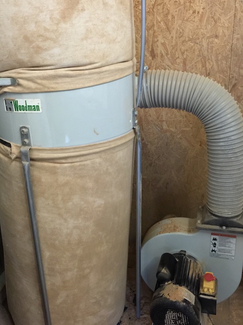
One proble I have encounter with left over pieces: 1. The suction does not work properly unless the piece of wood that is used for protection is thin and I use pieces around to fill the table to balance the suction.
This pictures shows the problem in the cutting toolpath in the preview function.
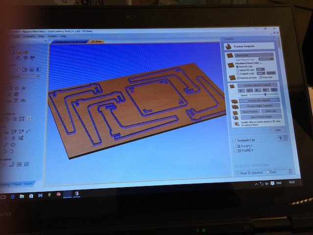
Opened vCarve and choosed my material and endmill 8mm, which was proposed for cutting 18mm plywood. I set up two layers for the job, one for the puckets, which will carve at 9mm deep and the second file to cut. So on the right pane I first choose the settings for the pocket and later for cutting. I have set them to make two passes of 4.5mm for pockets and 9.2mm for cuts for a total of 18.4mm cut to make sure we cut through the plywood. This makes a roughly nice job, not too steep each passes and not too slow, the CNC is very busy here so I had to make it quick.
Verifying that all toolpath is nice and clean.
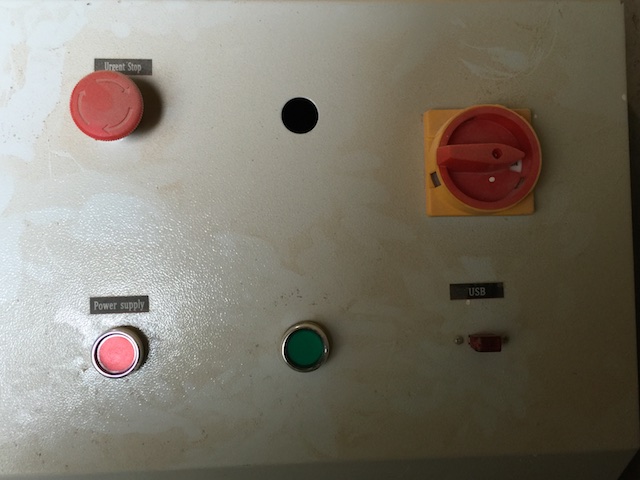
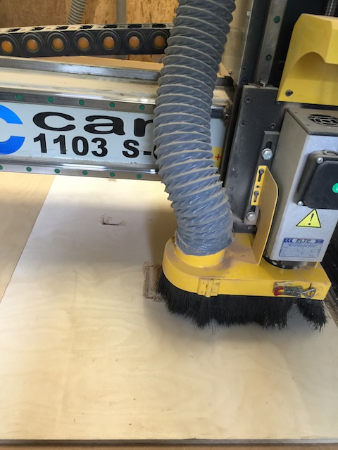
Start CNC and vacuum (green button) for suctionning the wood to keep them in position.
Zero the X, Y and Z axis. Note that I did the Z axis zero in the middle of the plywood to make sure I have the best data. Corners tends to be a bit bent. Start vacuum for dust and start the job.
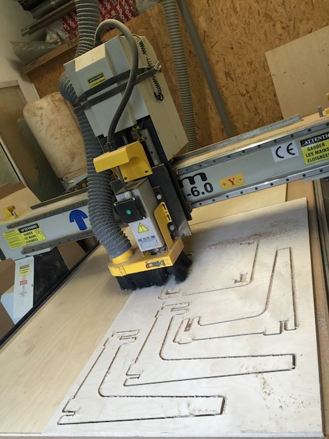
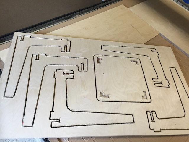
All went fine and pieces were nicely carved and cut!!!
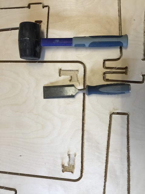
Took out the pieces with a hammer and knife, flat part on the side of my pieces.
Sanding the pieces.
Voilà!
Assembling and varnishing. Very happy about the result!