Electronics Design
This Week's Assignment:
Add a button and LED to the echo hello-world board. See details here.
-
EAGLE
Redraw the echo hello-world board.
-
Adding components
Add (at least) a button and LED (with current-limiting resistor)
-
Design rules
Learn the design rules, and make mill the board
-
Extra credit
Simulate its programation
Files
All files can be downloaded here .
Circuit board sofware
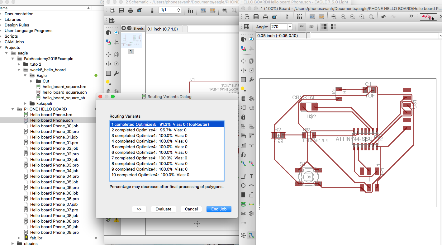
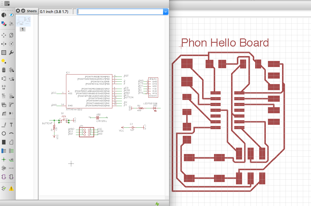
This week we are learning about electronic design. Redrawing the Hello board base on the tutorial one and adding a led and a button using Eagle Software. In Eagle I started by making new project. Under the project I made a Schematic and then generated a Board.
A schematic in electronics is a drawing representing a circuit. It uses symbols to represent real-world electronic components. The most basic symbol is a simple conductor (traces), shown simply as a line. If wires connect in a diagram, they are shown with a dot at the intersection.
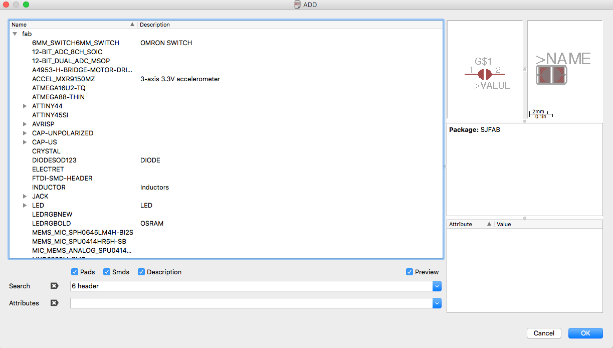
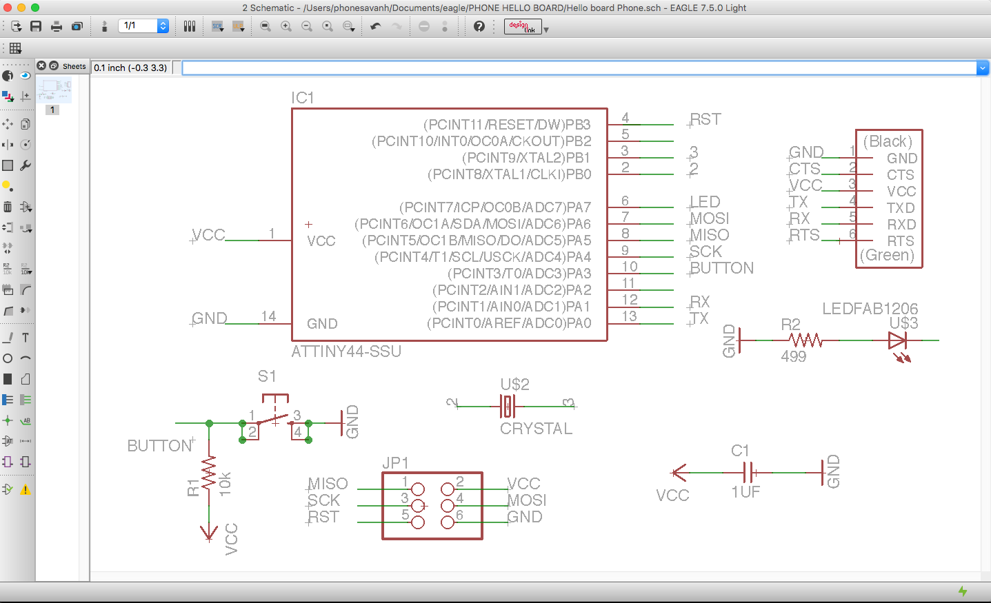 I add the Fab Library to the project and drop the componant on the schematics. I name the end of each component so that each end with the same name will connect together on the board view.
- 6-pin programming header to program the board
- Attiny44A microcontroller
- FTDI header for power supply and computer connexion
- 20 MHz Crystal, external crystal clock generator
- Capacitor for a better quality input current
- 10K esistors
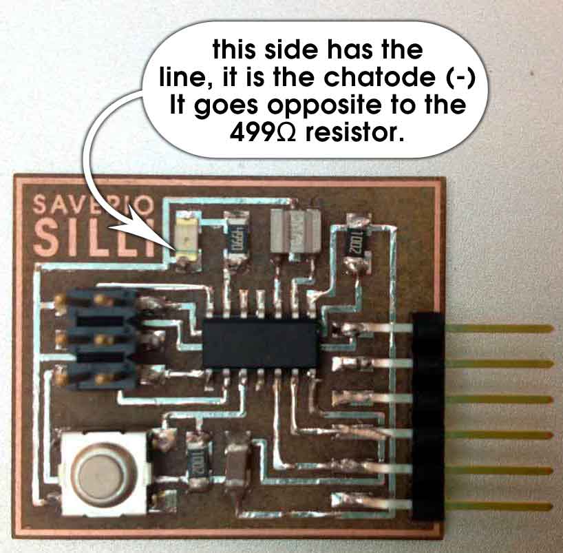
- Led for the excerise
- 499 Resistor to reduce led applied voltage
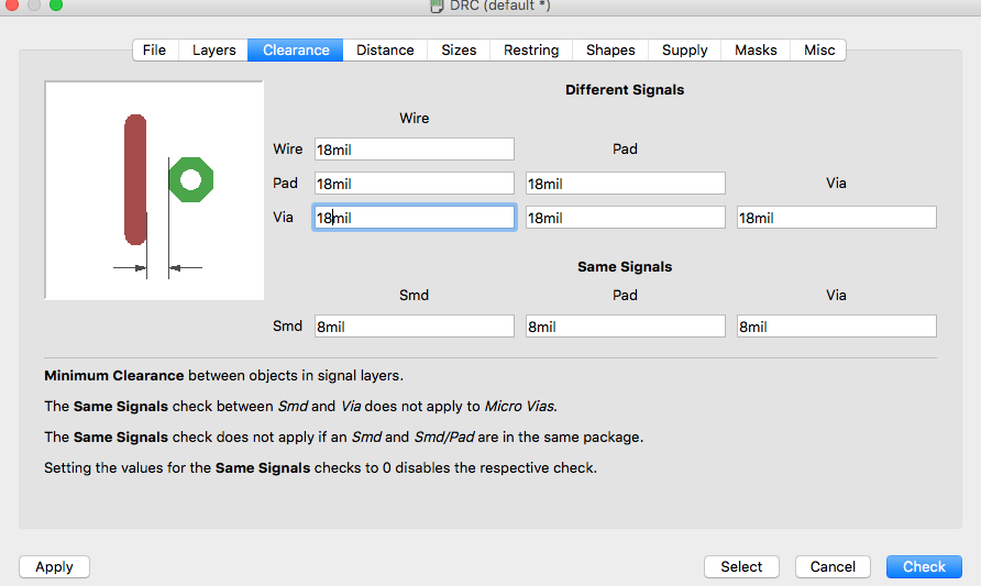
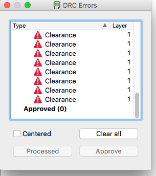
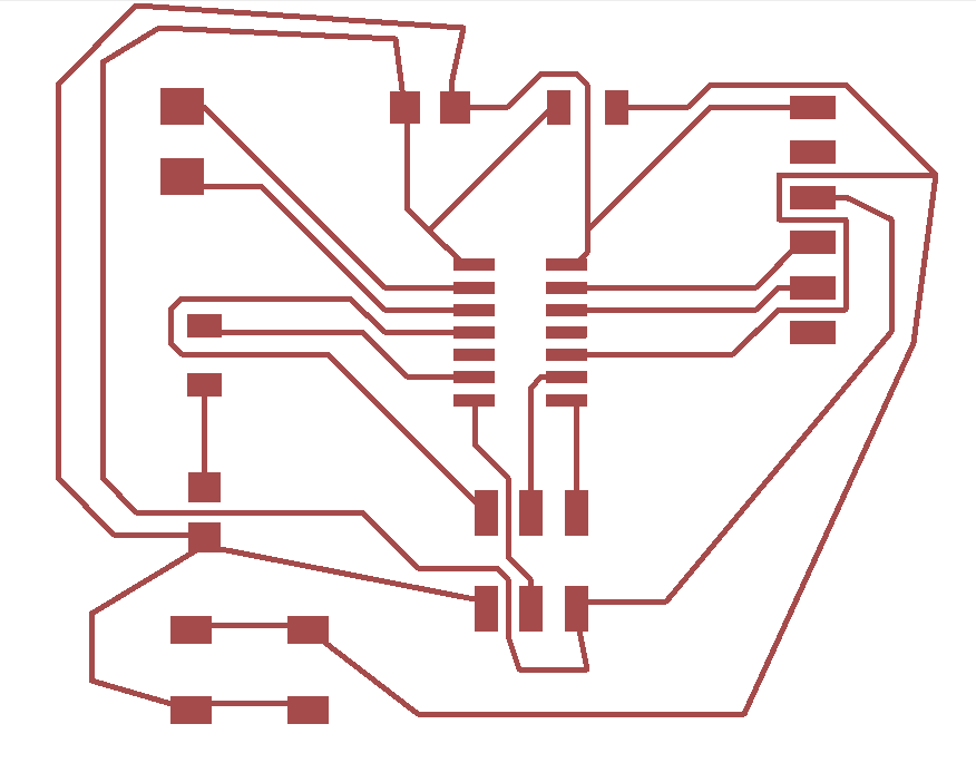
I generated a board and the drawing was not so clean (there were lost of lines going under the processor and 6 pins, it tooks lots of triasl and errors to regenerate the circuit until I added the design rules. Since the milling bit that will be used will be 1/64, I put in 18mil int the field to make sure there is enough space when cutting the PCB.
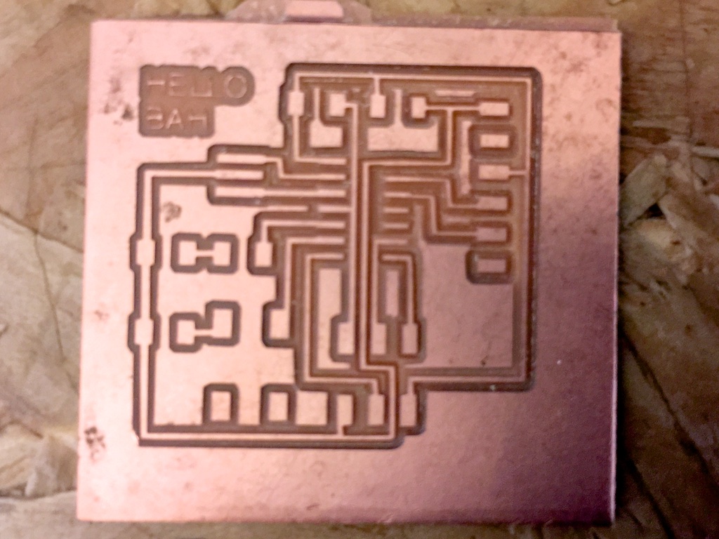
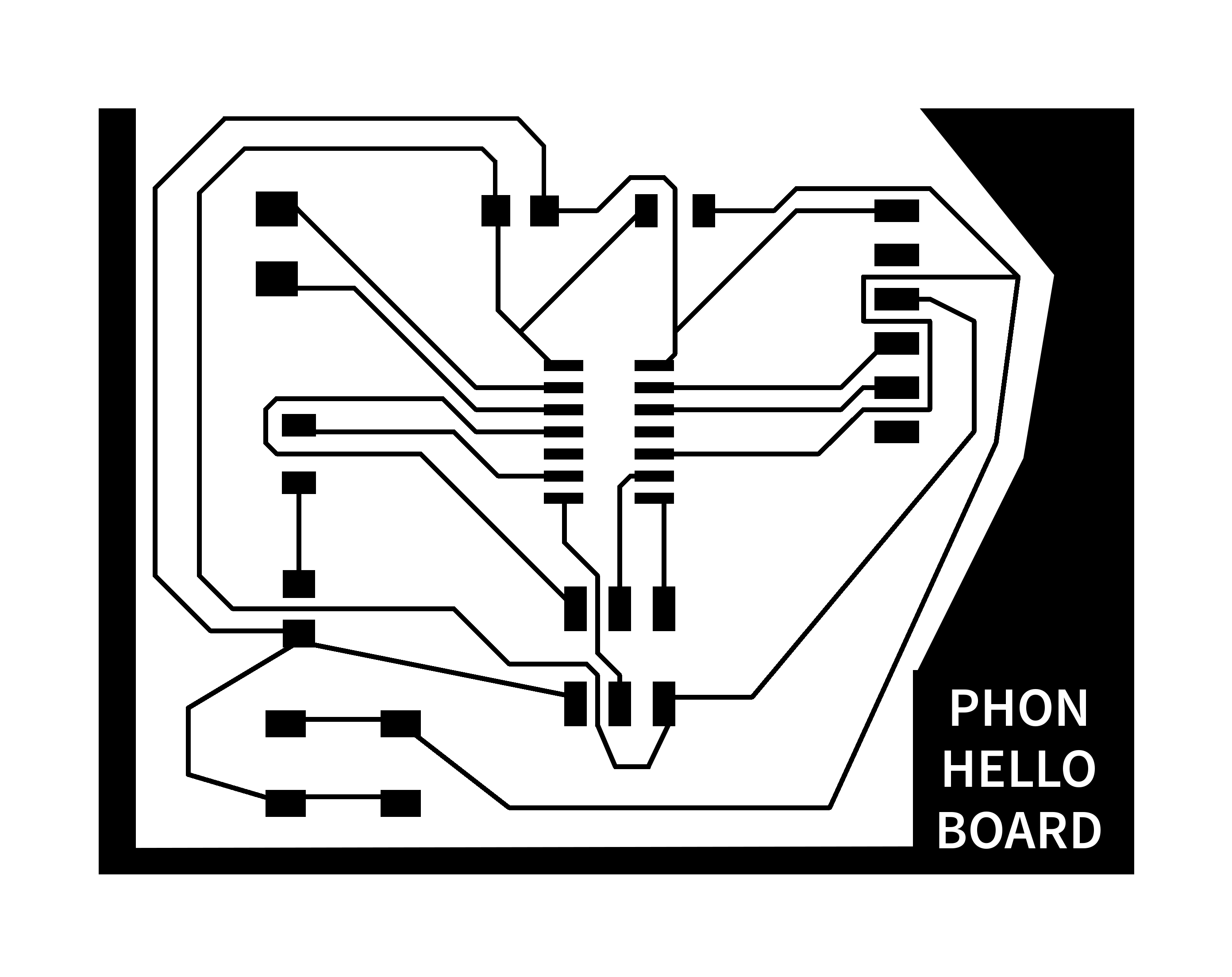
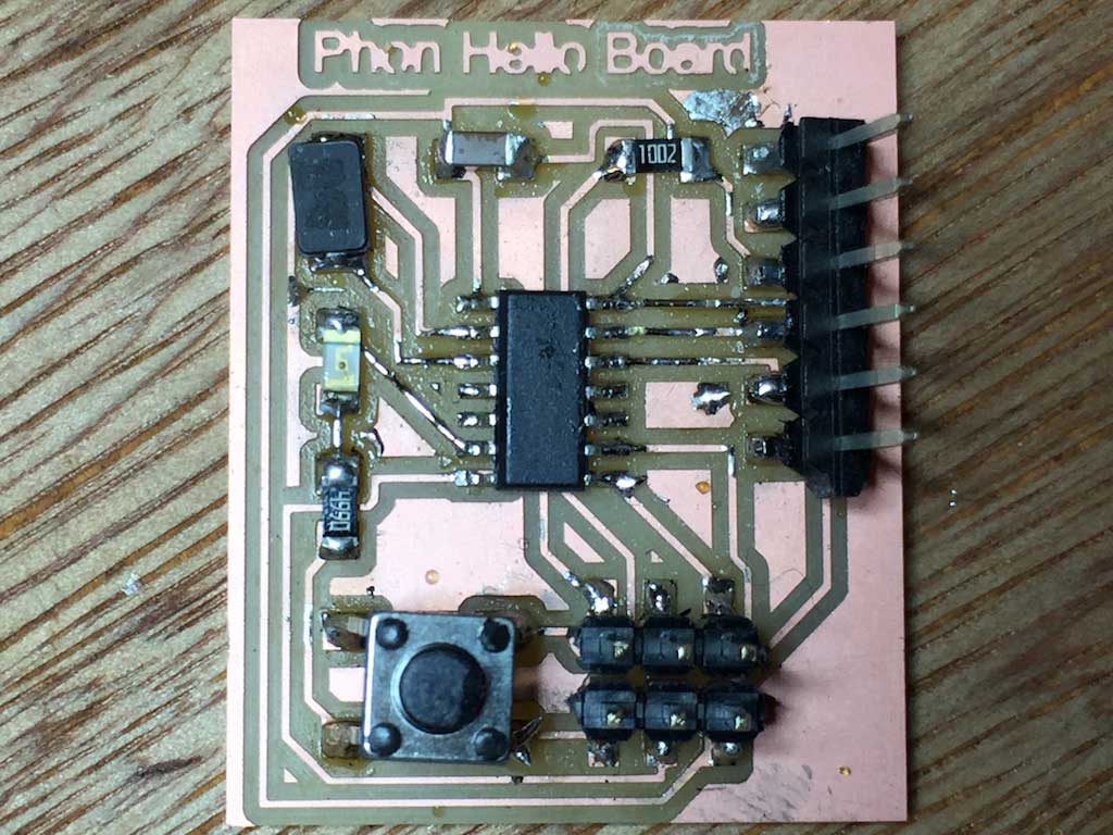
Bellow is the result of my board that I modified using Adobe Photoshop to make the lines cleaner and to add my name.

with the Roland SRM-20
Fab Modules
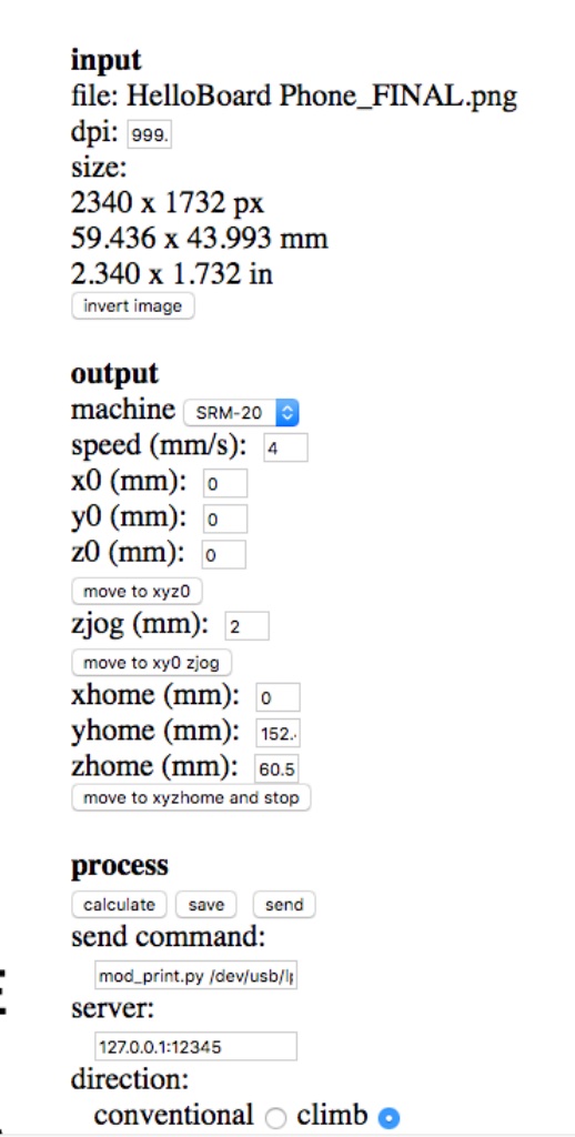
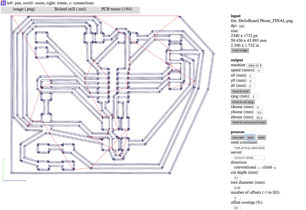
Preparing files for cutting, In Eagle, I have exported the files in monochrome image in PNG; used the fabmodules to generate the code, using these preferences below:
1. I went to the online fabmodules at http://fabmodules.org/
2. Selected input format and choose image PNG
3. Output format "Rolland mill (.rml)
4. PCB Traces (1/64)
5. On the right pane, under "input", I selected invert image if need be (the black color will be milled off)
6. On the right pane, under "output" I selected the name of the machine, in this case SRM-20.
7. I made sure to set X0, Y0, Z0, to value 0, otherwise it will offset to 1 cm.
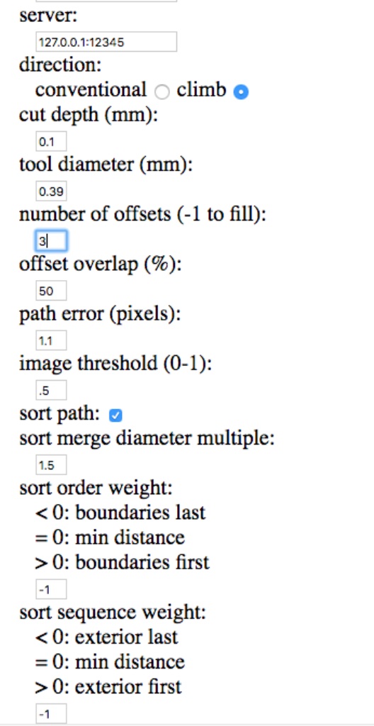
8. Set the number of offset to 3.
9. Click on calculate button and save my .rml file
10. I repeated the steps for the frame image, except for the end mill I chose 1/32 instead of 1/64 and chose 1 for number of offset.
 All my files may be downloaded here.
I read my Paris instructor page to guide me to this process.
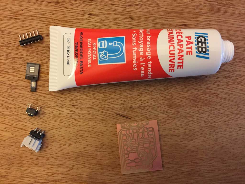
I soldered the board buy putting flux on the little pads and started from inside out. Thinned and then solder one side of the pad first.
Positionning of the light, very important
Rolland SRM-20
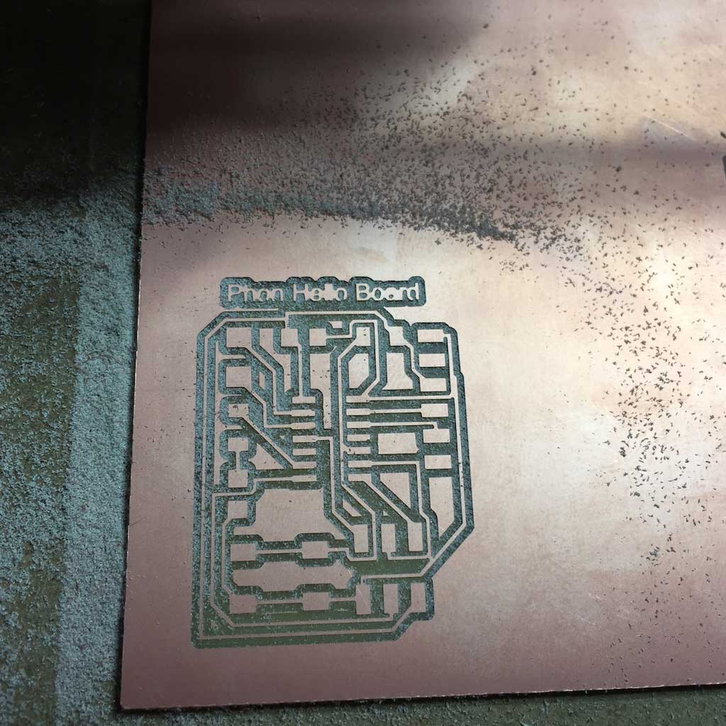
My old file was a bit larger compared to other students Hello board, 3x2 cm vs 5x6 cm. So I made another Hello Board. Another prcatice with Eagle software. One mistake I made, was to make a copy of my schematics that I named "Hello board Phone 2.sch" and worked on my board file named "Hello board Phone.sch". Result of this mistake is that I lost the second version of the board I made. But I was able to export the Monochrome image, cut it in the Rolland milling machine and soldered it. Because I needed to remake my third board file the path of my finished board is not the same as my file board. Both will work just as well.
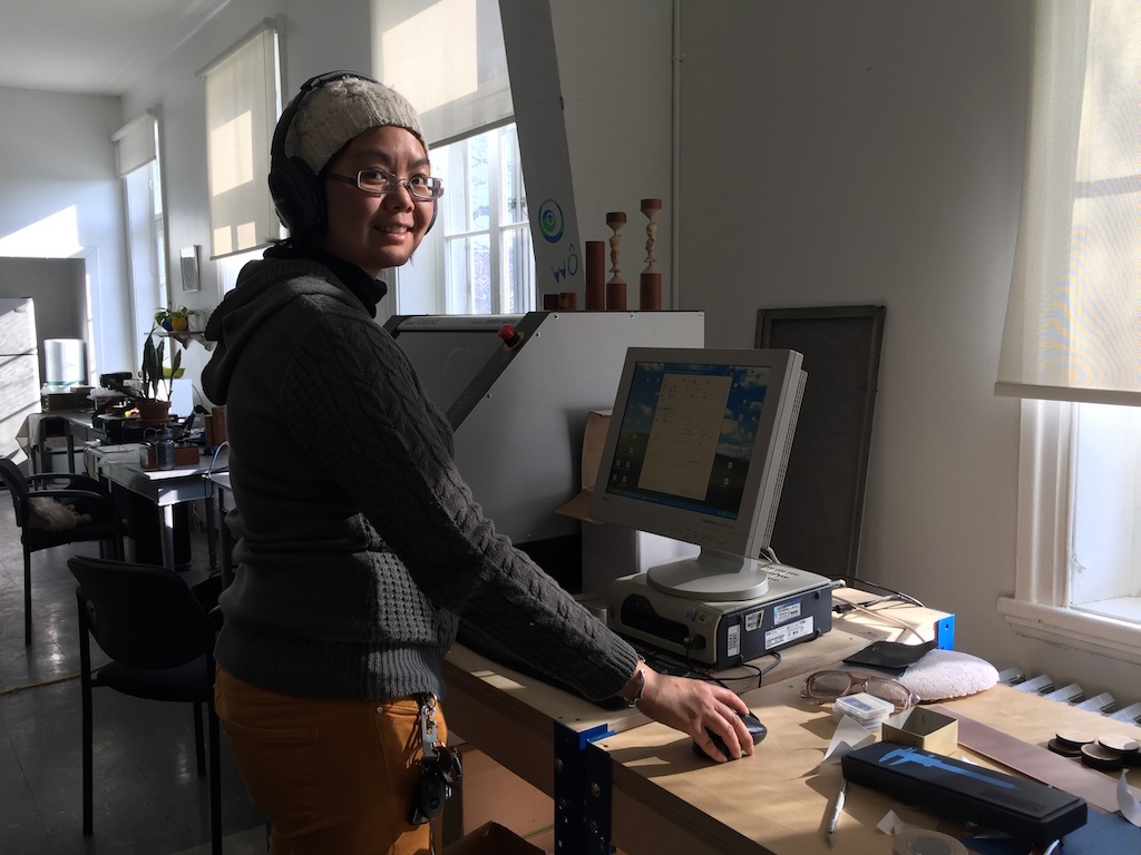
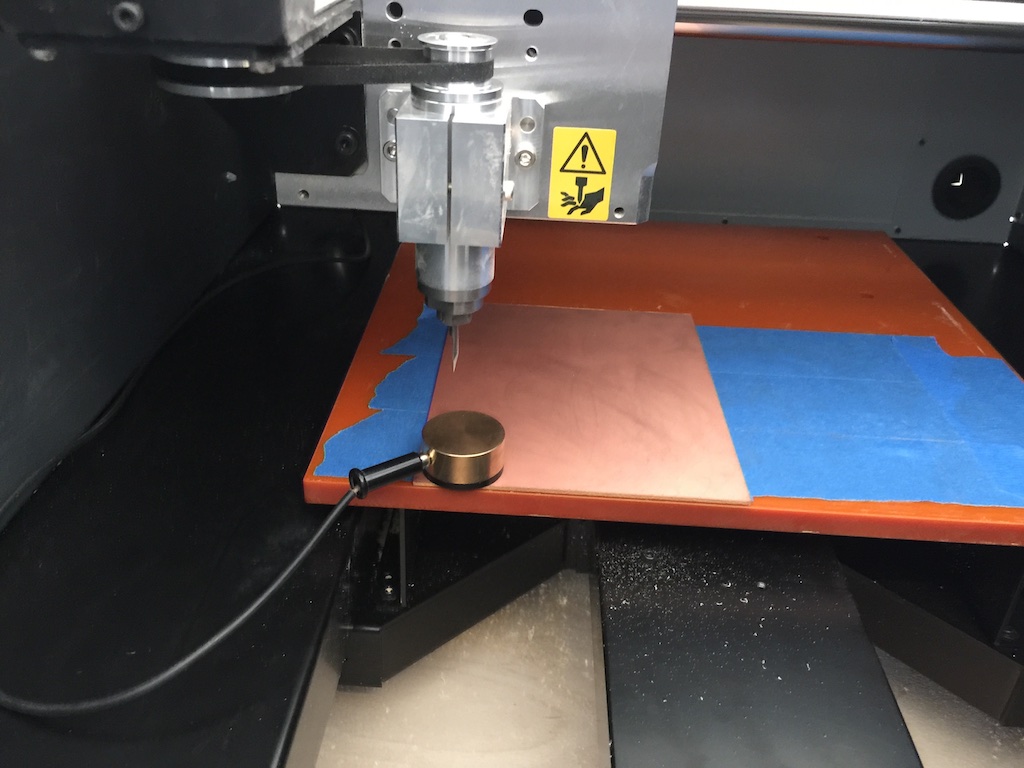
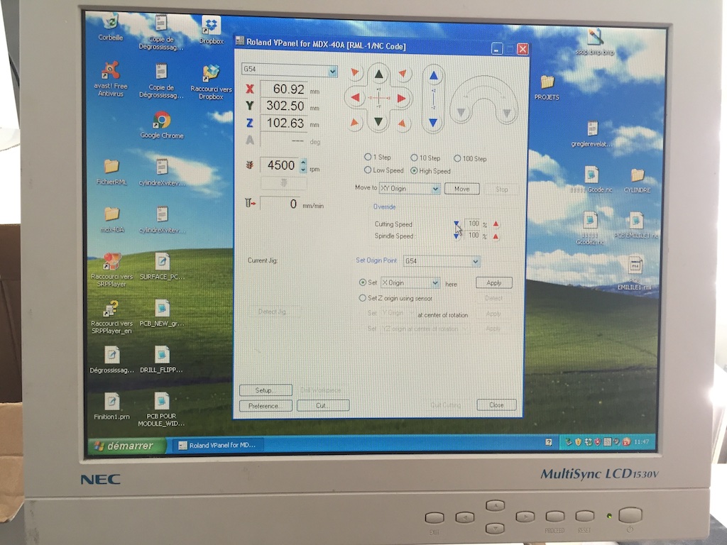
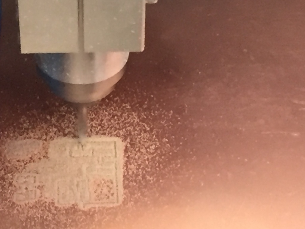
with the Roland MDX-40A
While in Montreal at Fab Lab du Pec, I have been playing with the desktop milling machine, the Roland Modela MDX-40A. Amazing machine. I have not yet at the time made my schematics so I used last year student to mille the board for testing. I used a CNC machine before to do my ISP and using this one just made it 10 time much easier.
I taped the copper FR1 sheet with carpet tape underneeth, used the PNG file to generate the gcode with the online fab modules and sent it to the machine. Zeroing it took less then a minute as it has a Z sensor. It took about 15 minutes only to make it. Almost twice less time then the fab isp made with the home made CNC at the Makerspace North.