1. Intro
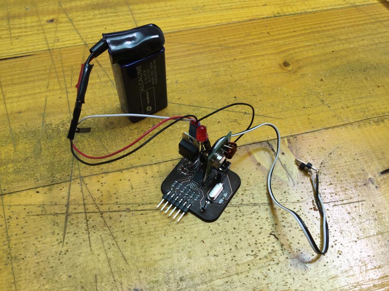
For this assignment I used the board made for Input Device and a satshakit I made during the week 8. I used the cheap RF modules (transmitter and receiver), these have an integrated antenna.

2. The Transmitter board and firmware
The Transmitter board use the ADCTouch library that allows to have a capacitive sensor with just one Analog Pin connected to a resistor (10k in my case) instead of 2 digital pins and 2 resistors. This library take advantage of the internal architecture of the atmega in order to do this.
ADCTouch libraryExplanation of how it works
Eagle files
Svg file for lasercut
The library I used to send data through the RF module is Virtual Wire, the radio can sand just one byte at a time, in order to send all the 6 values of the pads these are mapped to a range of 0-255.
Virtual Wire
Transmitter Arduino Sketch
3. The Receiver firmware
The receiver takes the bytes sent by the transmitter, stores it in one array and send these to Processing through the Serial.read function. The values are separated by commas and ends with a line, these are informations that helps to parse the data in processing
Receiver Arduino Sketch
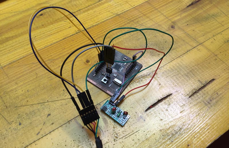 The receiver module is connected to Pin 11, GND and VCC
4. The result
Go back in Home