1. Intro
The input board I decided to make is a capacitive wireless board. The future idea is to use this board for an event: while a projector is running a visual on processing, you can attach the wireless capacitive board to a poster (screen printed with conductive ink) and touching the printed graphic you can change and interact with the visual projected. So far i've just built on processing a simple interface to help me during the debugging. .
The board
This board use the ADCTouch library that allows to have a capacitive sensor with just one Analog Pin connected to a resistor (10k in my case) instead of 2 digital pins and 2 resistors. Cause I prototyped the board with a satshakit I decided to modify the satshakit micro made by Daniele Ingrassia. I deleted all the unnecessary stuff and added: the headers for the analog pins and added, a voltage regulator in order to use a battery and a rf transmitter module.

Eagle files
Svg file for lasercut
The soldered board:
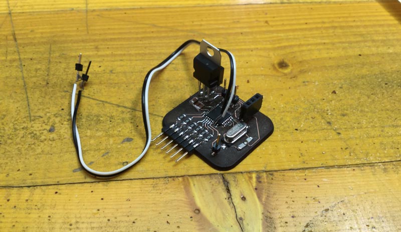
As you can see in the picture I had to mod the board, a new design should have RX and TX header (yep, I forgot it), a led integrated, and if you want to program it directly with the ftdi cable a second RST header connected to a 100n capacitor and closing to VCC (with 10k resistor) will be needed
3. Firmware
This board use the ADCTouch library that allows to have a capacitive sensor with just one Analog Pin connected to a resistor (10k in my case) instead of 2 digital pins and 2 resistors. This library take advantage of the internal architecture of the atmega in order to do this.
ADCTouch library
Explanation of how it works
Cause the value changes in relationship of the conductive pad extension, conductivity and design, I made a simple function that runs once on start that allows to calibrate the min and max values of the pads. When power is plugged the led will light on for 3 secs indicating that you can start touching the first one (A0), when the led turn off means that the calibration for that pad is done; when the led turn on again you can touch the second one(A1) and so on. At the end of this process the led will blink 3 times, this indicate that the microcontroller is going to store the minimum values, during this the pads shouldn't be touched.
Transmitter Arduino Sketch
4. The result
Wuth Calibration:
Go back in Home