Week #12 INPUT DEVICES
Assignment
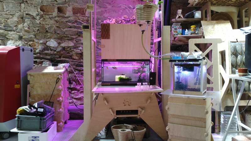
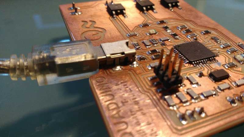
Aquaduino
The whole goal of this week for me was to create my own Arduino version customized for Aquaponics (Aquaduino) and use it as well as my input device. The reason I'm doing this is for later use this board for my final project
One of the things that make this project special is that I´m using an ATMEGA32U4, that has FTDI integrated, so you can, after burning bootloader, program your board using an USB Mini B. The ATmega32U4 is the same microchip used on Arduino Leonardo. I based myself upon many designs out there. I used the Eagle Schematics from the Leonardo itself, from:
- the Xduino 8.0,
- the ATmega32U4's datasheet,
- Jonathan Grinham's FabLeo which I had to access via WAYBACKMACHINE
- and a lot of Ferdi's help (Our Guru here at Fab-Academy Bcn)
Aquaduino is a simplified version of an Arduino Leonardo. No reset button, just one led on pin 13, an ICSP for its first programming, some Pins but not all available. I designed it to be easily hacked.
Before we start, what inputs are important to monitor in aquaponics ?
Water is the life-blood of an aquaponic system. It is the medium through which all essential macro- and micronutrients are transported to the plants, and the medium through which the fish receive oxygen. Thus, it is one of the most important aspect to monitor for successful aquaponic food production. Five key water quality parameters have to be considered dissolved oxygen (DO), pH, temperature, total nitrogen, and water alkalinity. Each parameter has an impact on all three organisms in the unit (fish, plants and bacteria), and understanding the effects of each parameter is crucial. Although some aspects of the knowledge on water quality and water chemistry needed for aquaponics seem complicated, the actual management is relatively simple with the help of simple test kits. Water testing is essential to keeping good water quality in the system.
For this first version of Aquaduino, I envision to start monitoring:
- pH : The pH of the water has a major impact on all aspects of aquaponics, especially the plants and bacteria. For plants, the pH controls the plants’ access to micro- and macronutrients. At a pH of 6.0–6.5, all of the nutrients are readily available, but outside of this range the nutrients become difficult for plants to access. In fact, a pH of 7.5 can lead to nutrient deficiencies...
- Electrical Conductivity (EC): EC is commonly used to measure the total amount of nutrient salts in the waterwhich which is directly linked to nitrate and other macro and micro nutrients concentration that interest us for plants growth.
- Water T°C : Water temperature affects all aspects of aquaponic systems. Overall, a general compromise range is 18–30 °C. Temperature has an effect on DO as well as on the toxicity (ionization) of ammonia; high temperatures have less DO and more unionized (toxic) ammonia.
Dissolved oxygen is the water quality parameter that has the most immediate and drastic effect on aquaponics. Indeed, fish may die within hours when exposed to low DO within the fish tanks. Thus, ensuring adequate DO levels is crucial to aquaponics. However monitoring DO levels is very important, it is quite challenging because accurate DO measuring devices are very expensive or difficult to find . It is often sufficient for small-scale units to instead rely on frequent monitoring of fish behaviour and plant growth, and ensuring water and air pumps are constantly circulating and aerating the water. In a next Aquaduino iteration, I will include it.
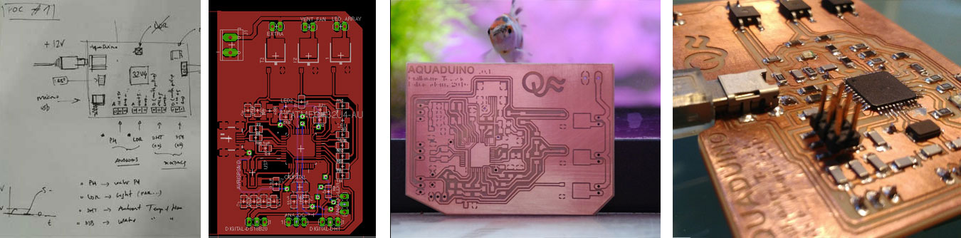
Drawing the AQUADUINO V0.1 on a piece of paper

Before jumping on Eagle, I sat down with our local Guru to draw on a piece of paper, what I will need to add//remove on the top of Arduino Leonardo to make it work. We also decided to include the outputs on the same board. For more info about outputs, please check the Week 14 assignment
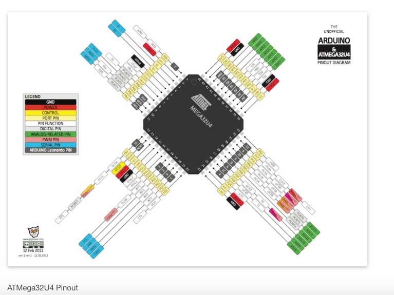
The ATMEGA32U4
There you go, the beast!

I found this image which is very helpful, knowing what is what in your ATMEGA32U4. Thank you apighixxx.com.
As you can see, the grey frame is the pin scheme exactly as they are in Arduino Leonardo, making it easy for you to program it afterwards with Arduino IDE.
Designing in Eagle
Starting with Fab Leo schematic
As I mentioned above, I started the Aquaduino based on FABLEO schematic removing reset Button, some LEDs and several pins. The reason behind it is to simplify the design keeping only crucial elements.
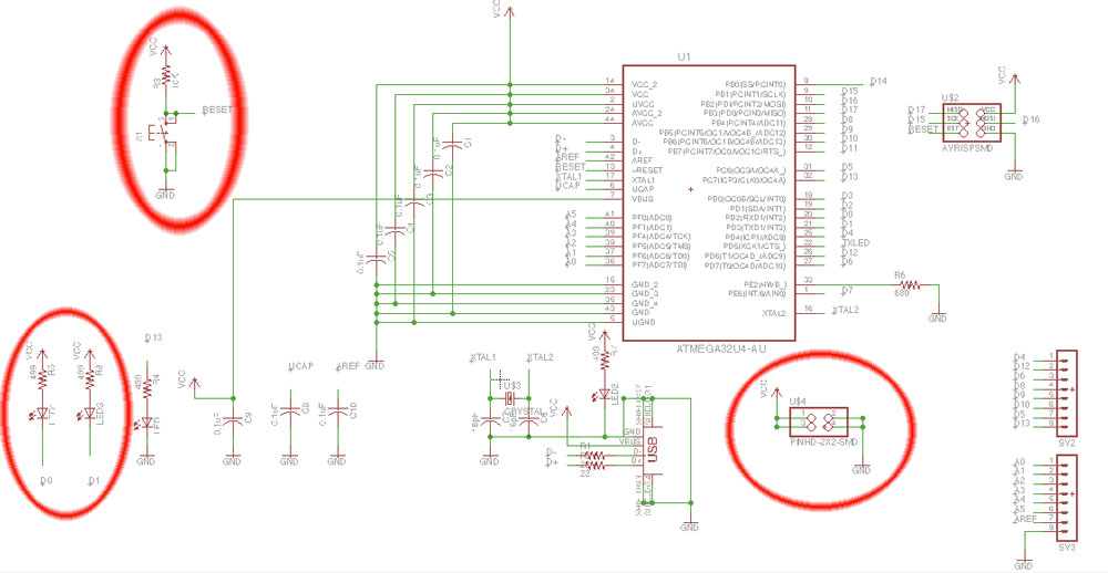

Apart of removing components, I simplify the numbers of pins connected to the Microcontroller to connect the 4 sensors mentionned above. Each sensor will have it's respective 3 Pins header including VCC and GND.
Adding 2 x Analog inputs (pH and EC)
Looking at the ATMEGA 32U4 PinOUt diagram, I allocate 2 analog Pins (i.e. A0-PF7- and A1 -PF6) for the pH and EC sensors.
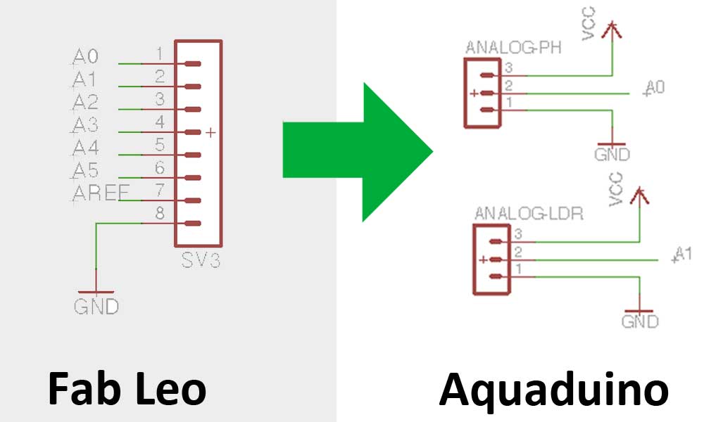
When it comes to the EC and pH sensors provider, I use the ones that Open Agriculture initiative from MIT Media Lab is using as described on their respective Bill Of Materials on Github. These sensors have been designed specially for Arduino controllers and has built-in simple, convenient and practical features. It enables a simple connections according to the following diagram and after uploading the program, you will be able to measure the pH and EC values easily.

When it comes to pH sensor I used this Analog pH Meter Pro model
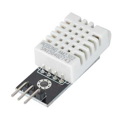
Adding 2 x Digital inputs (water T°C and air humidity & temperature)
When it come to digital input it is good to add a pull-down resistor between the middle pin of the sensor and the 5v line.
EXPLAIN WHY
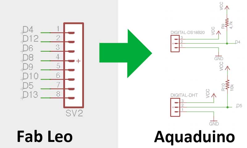
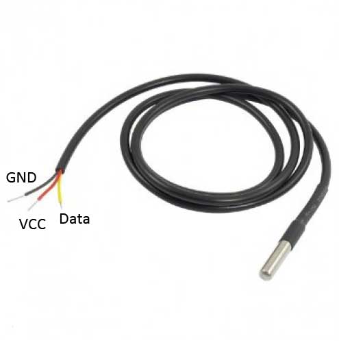
To monitor the water T°C sensor I will use the DS18B20 water proof sensor. According to the litterature, the value of its respective pull-down resistor shoudl be a 4k7 (4700 ohms). As we don't have it in the fab Lab, I will use a 4k9 (4900 ohms).
To monitor the air T°C and humidity I will build a DHT22 Temperature and Humidity Sensor that need a 4k7 (4700 ohms) pull-down resistor. According to the litterature, the value of its respective pull-down resistor shoudl be a 10k (10 00 ohms).
Aquaduino schematic & Bill of Materials (BoM)
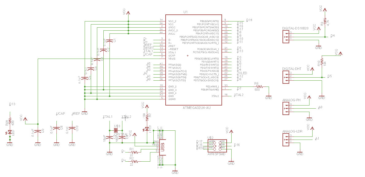
Partlist exported from C:/Users/LuizHenrique/Documents/eagle/Luizino/luizino02.sch
- Part / Value / Device / Package / Description
- C1 0.1uF CAP-US1206FAB C1206FAB
- C2 0.1uF CAP-US1206FAB C1206FAB
- C3 0.1uF CAP-US1206FAB C1206FAB
- C4 0.1uF CAP-US1206FAB C1206FAB
- C5 0.1uF CAP-US1206FAB C1206FAB
- C6 18pF CAP-US1206FAB C1206FAB
- C7 18pF CAP-US1206FAB C1206FAB
- C8 0.1uF CAP-US1206FAB C1206FAB
- C9 0.1uF CAP-US1206FAB C1206FAB
- C10 0.1uF CAP-US1206FAB C1206FAB
- LED LED1206 1206
- LED LED1206 1206
- R1 22ohm RES-US1206FAB R1206FAB Resistor (US Symbol)
- R2 22ohm RES-US1206FAB R1206FAB Resistor (US Symbol)
- R26 499 RESISTOR1206 1206
- R6 680 RES-US1206FAB R1206FAB Resistor (US Symbol)
- R7 499 RESISTOR1206 1206
- R9 4700 ohm RES-US1206FAB R1206FAB
- R10 10000 ohm RES-US1206FAB R1206FAB
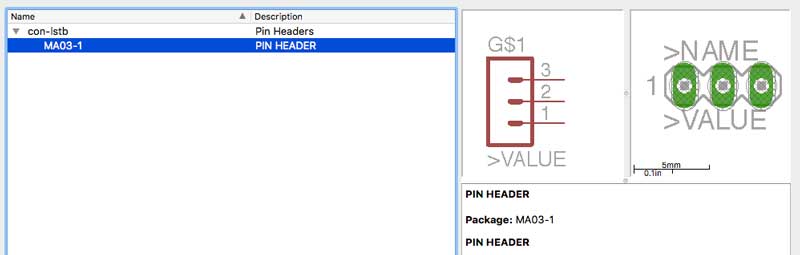
- SV1 MA03-1 Pin PIN HEADER
- SV2 MA03-1 Pin PIN HEADER
- SV3 MA03-1 Pin PIN HEADER
- SV3 MA03-1 Pin PIN HEADER
- U$1 USB_MINIB USB_MINIB USB_MINIB
- U$2 AVRISPSMD AVRISPSMD 2X03SMD
- U$3 CRYSTAL CRYSTAL 2-SMD-5X3MM
- U1 ATMEGA32U4-AU QFP80P1200X1200X120-44N 8-bit Microcontroller with ISP
- Flash and USB Controller
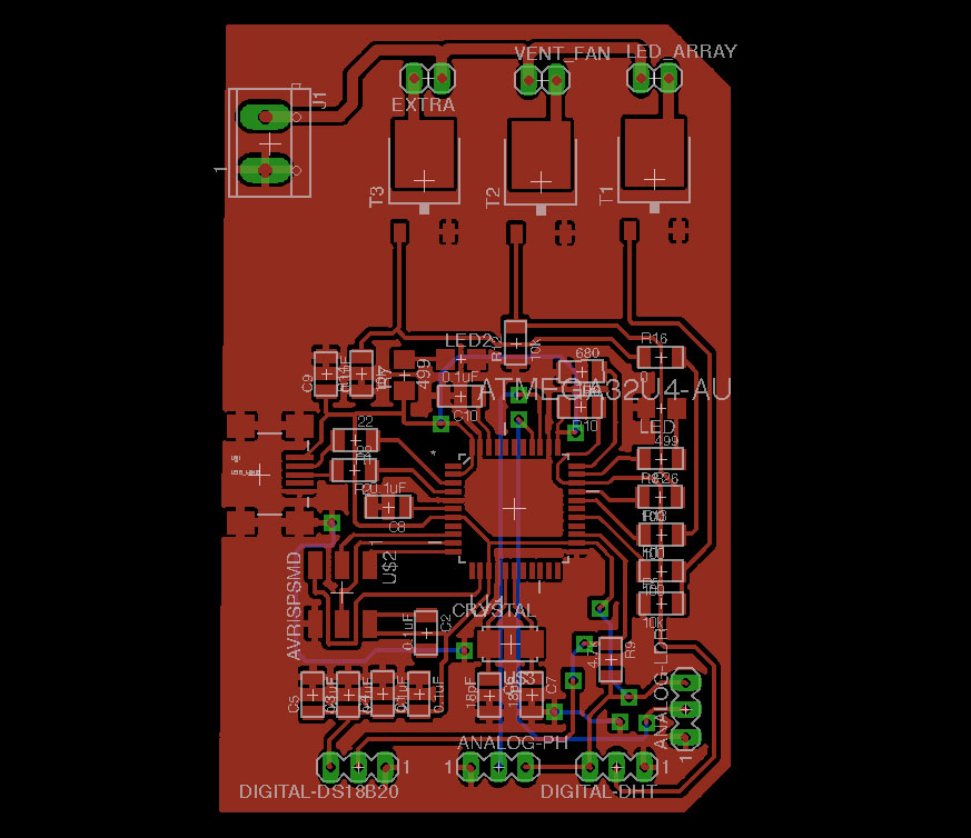
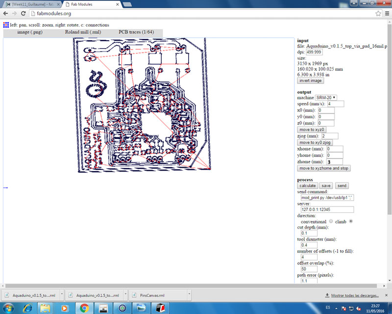
Route the traces on the board
Design Rules
Before starting to route the traces on the board, it is important to set up the correct Design Rules which are usually based on the drill diameter used to mill the traces. In my case I will use a 1/64 (i.e. 16 mill).
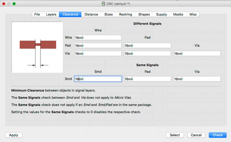
The Thermal insulation parameter is used when substracting pad shapes from signal polygons.

Route the traces
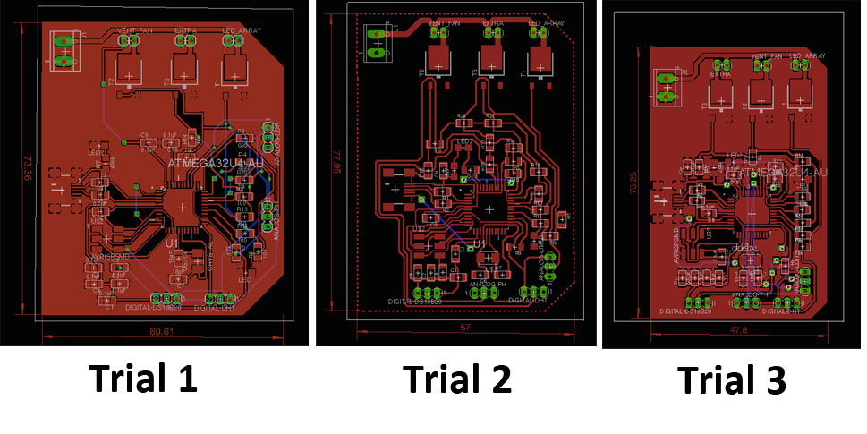
Looking at how the Fab Leo was routed, I tried several design before arriving to Trial #3.
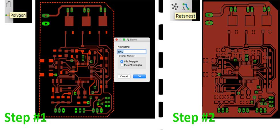
Polygons and ground fills
In Eagle polygons are used to make big copper areas on a PCB that aren’t necessarily traces. We use them all the time to fill blank space on a PCB with copper connected to ground. In a sense, it allow you to simplify the number of traces on your board.
I learn a lot looking at the following tutorial on Polygons and ground fills for PCBs in Eagle
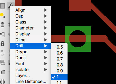
Define drill diameter to 1mm
As I'm working with vias, I will need to pass 1mm diameter connection to bridge the top and bottom part of the board, so I need to make sure that my drill diameter is 1mm large. To do this I've used the Change / Drill option on the left hand side bar
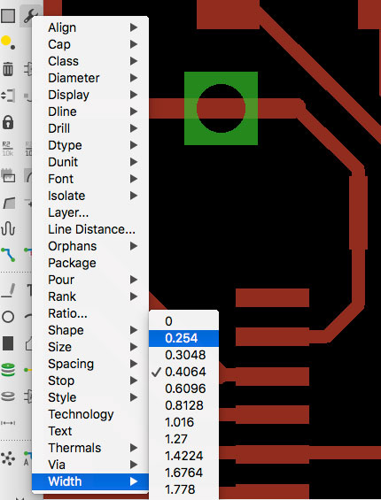
Define traces width to 0.254
The distance between the ATEMAGA 32U4 pins is 0,4 mm that is slighty lower than the 16 mill diameter of the 1/64 drill (i.e. 0,4064)
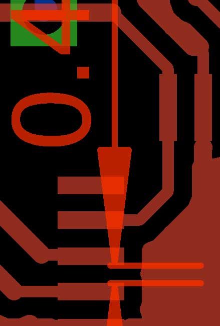
So the respect the Design Clearance Rules, I need to reduce the width of traces connected the pins
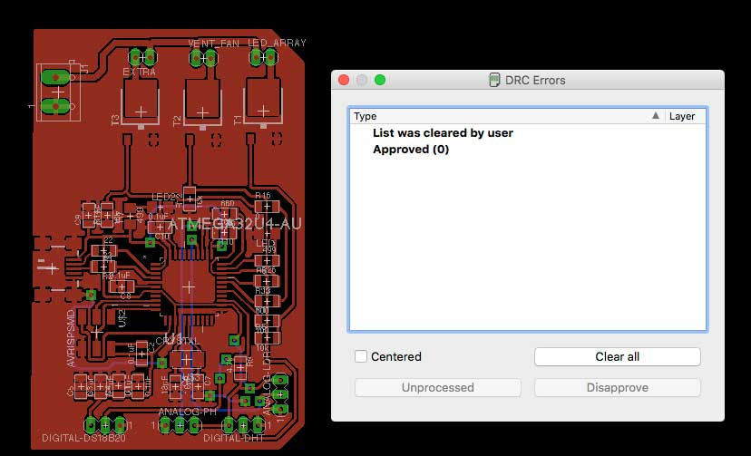
Checking for errors before sending it to Fab modules
Before we send it off to Fab Modules there are a few tools we can use to check our design for errors. This tutorial on Sparkfun has been of a great help
- Rasnet The first check is to make sure you’ve actually routed all of the nets in your schematic. To do this, hit the RATSNEST icon – – and then immediately check the bottom left status box. If you’ve routed everything, it should say “Ratsnest: Nothing to do!”
- DRC is the command used to test design for electrical errors.
- ERC is the command used to test schematics for electrical errors.
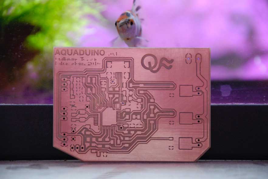
Here is the beast !
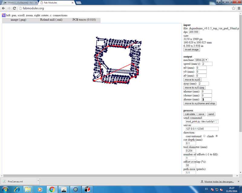
Preparing PNG for Fab Modules
As you might already know, to mill our boards we are using fabmodules.org, and for that I exported my files as PNG, one of the formats that FabModules opens. You might want to save it in very high resolution (around 700dpi) so your traces get very precise once fabmodules converts it.


To mill the bottom part of the board it is important to remember that will need to flip your board so does your design :)

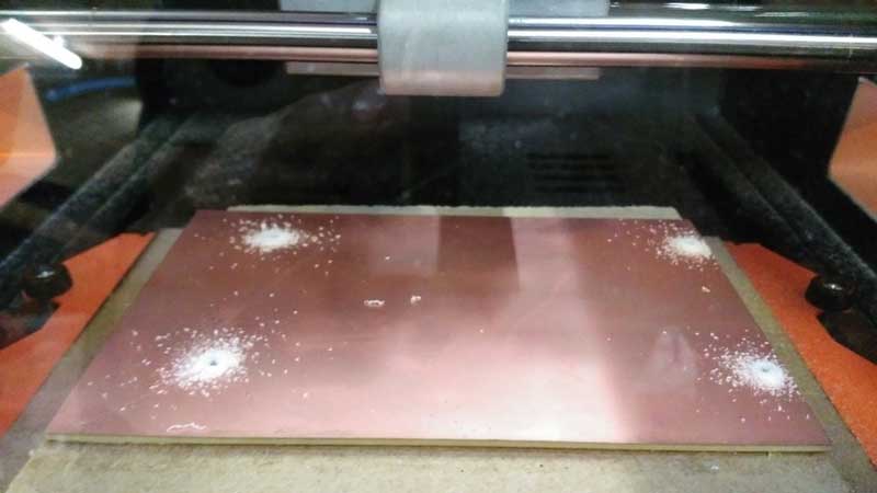
It's Milling Time:
I will use the SMR-20 Rolland to mill this board. Before cutting you need to set up the XYZ home to zero. Then you are ready to go.
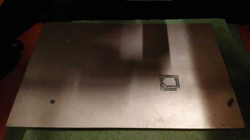
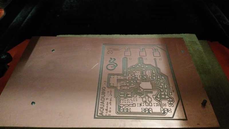

It look gooooood!
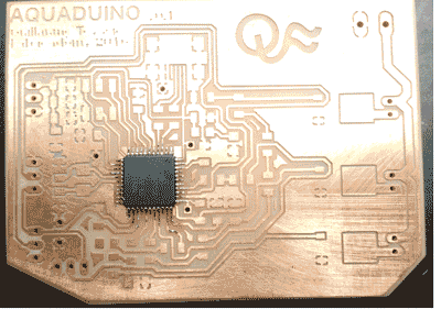
Stuffing
...and that's how it went:
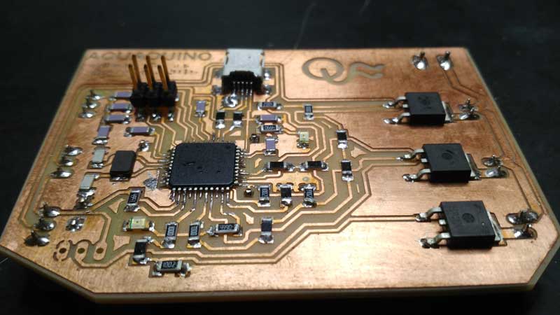


Programming the Aquaduino
When I plug the Aquaduino into my computer via the mini USB cable, I get an error message telling me that the board is drawing too much power and that the computer is shutting down the USB port. It means that I should have a short cut somewhere on your board.
Troubleshooting short circuits

First, I did a visual inspection of the board and reflow any solder joints that look cold (not shiny and smooth).
Then, get out the multimeter and check all the connections to make sure that:
- power and ground are not connected
- all ground are connected
- there is not a short on the power line

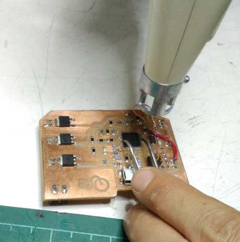

After putting back the MCU and pluguing it back, the LED turn green ! Aquaduino is powered !
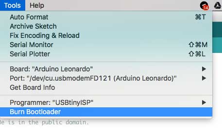
Burnloading with FabISP

To Burnload the ATEMAGA32U4, I used Arduino IDE to program it, plus my FabISP. Once the Aquaduino board was recognized, in Arduino IDE, select Tools menu, Board: Arduino Leonardo (Leonardo Board has the same ATMEGA32U4), Then Tools again -> Burn Bootloader.
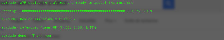
New surprise, it didn't work and receive the following message

Using the terminal and the following command
avrdude -c usbtiny -P usb -p m32u4
I tried to communicate with the MCU and get the following message

And what I should get is the following
Water temperature as Input device n°1
Steps
The one wire Digital Temperature Sensor - DS18B20 from Maxim ,formerly Dallas, (that cound be found on Github) is a great chip for measuring temperature in wet environments. Luckily, there is a Dallas Temperature library for the arduino which makes using this sensor very easy.

Just download a copy of the library. In it you will find two folders. Drag and drop the DallasTemperture folder into your arduino/libraries folder. If you dont already have the OneWire library then you will need to copy that folder into the libraries folder also.
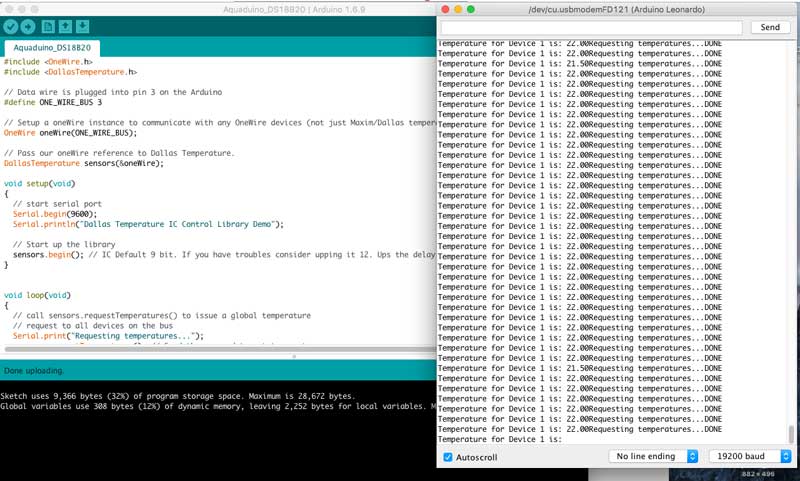
Next, load up the sketch below and upload it to your Arduino board. Using the Dallas Temperature Library makes getting the temperature easy.
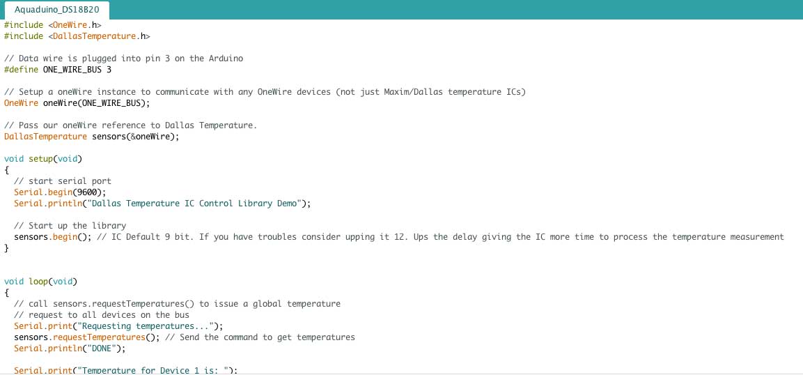
Sample Code
When you have uploaded the sketch, click on the Serial Monitor and you should see output like the following. The temperature is in degrees C
pH as Input device n°2
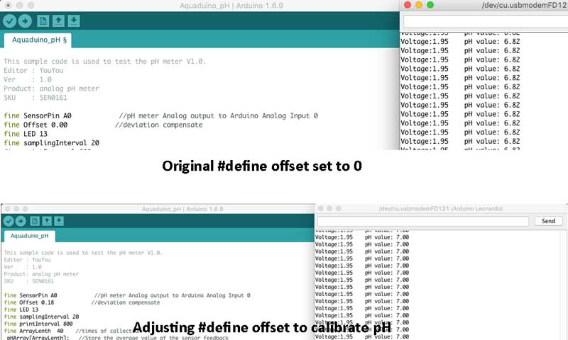
The code is directly taken from Wiki page of DFRobotics PH meter where I bought the pH probe
Steps
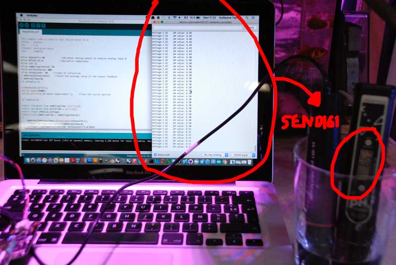
- The pH electrode is connected to the BNC connector on the pH meter board, and then use the connection lines, the pH meter board is connected to the analog port 0 of the Aquaduino. When the Arduino controller gets power, you will see the blue LED on board is on.
- Upload the sample code to the Arduino controller.
- Put the pH electrode into the standard solution whose pH value is 7.00, or directly shorted the input of the BNC connector. Open the serial monitor of the Arduino IDE, you can see the pH value printed to it, and the error does not exceed 0.3. Record the pH value printed, then compared with 7.00, and the difference should be changed into the "Offset" in the sample code. For example, the pH value printed is 6.88, so the difference is 0.12. You should change the # define Offset 0.00 into # define Offset 0.12 in the sample code.
- Fine adjustment
- For Acid solution: Put the pH electrode into the pH standard solution whose value is 4.00. Then wait about a minute, adjust the Gain Potential device, let the value stabilise at around 4.00. At this time, the acidic calibration has been completed and you can measure the pH value of an acidic solution.
- For Alkaline solution: According to the linear characteristics of pH electrode itself, after the above calibration, you can directly measure the pH value of the alkaline solution, but if you want to get a better accuracy, you can recalibrate it with the standard solution, pH = 9.18. Also adjust the gain potential device, let the value stabilise at around 9.18. After this calibration, you can measure the pH value of the alkaline solution.
NOTE:
                If you want to measure the pH value of other solution, you must wash the pH electrode first!
                The power supply is closer to +5.00V, the more accurate pH reading you could get.
Sample Code
The sample code I used for testing the PH meter and get the sensor feedback from the Arduino Serial Monitor could be found on the Wiki page of DFRobotics PH meter
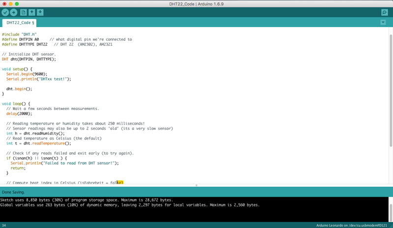
Air Temperature and Humidity as Input device n°3
Adafruit have a DHT11//DHT12 library and example code that makes it easy to test the DHT11 and get values to display on the serial window of the Arduino IDE.
Steps
- Download the library from Adafruit, , the link takes you to the "GitHub" page . Look for the zip file download button.
- Unzip the files into your libraries folder. The best place to unzip to is under your "My Documents\Arduino\Libraries" folder - later if you upgrade the Arduino IDE the library will still be there.
- If you browse to your libraries folder you should see a new folder named DHT-sensor-library-master Rename it to DHT
- Connect up your Arduino and start the IDE
- Look under File -> Examples -> DHT and open DHTtester.
- You will need to comment the line startng with #define DHTTYPE DHT22 by putting a // in front of it and then uncomment the line starting with //#define DHTTYPE DHT11by removing the two leading//'s.
- Upload the sketch then open the serial window. You should see the temperature and humidity level scrolling. If you breathe onto the sensor you should see the temperature and humidity rise. It will take a few seconds as the sensor is slow.
Sample Code
In the example sketch the temperature and humidity variables are defines as "float", i.e. they have decimal places. This can be changed to an "int" to remove the decimal places as they aren't needed in this project.
Find the lines:
- float h = dht.readHumidity();
- float t = dht.readTemperature();
- and change them to:
- int h = dht.readHumidity();
- int t = dht.readTemperature()
Upload the sketch and check the results in the serial window. You should see the temperature as whole rather than decimal numbers.
My test sketch:
Download
You access and download all the files generated during this week from my google drive:
- FABLEO's Eagle Schematic and Board + PNG ready to be sent to Fab Modules
- Open AG MIT Media Lab // Food computer Github repository
- Aquaduino v0.1 Eagle files (schematic & board)
- Aquaduino v0.1 PNG files
- Aquaduino v0.1 .rml files
- DS18B20 Arduino code
- Analog pH Meter Kit SKU: SEN0169 Arduino code
- DHT22 Arduino code
Conclusion
This week assignment turns into a 2,5 weeks to masterize the entire workflow from the first draw until the board
was working. Along the process I can't remember all the issues I faced, but
learning by failures it one of the best way to learn.

 At the end, what a relief when it's working ! . A next step is to connect an LCD display and see all these data on it.