Week #14 OUTPUT DEVICES
Assignment
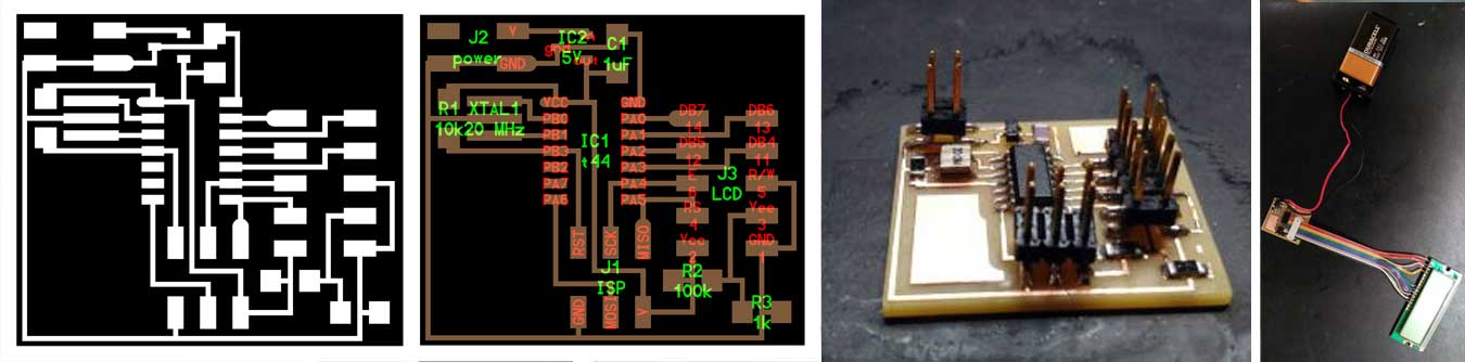
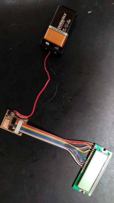
Hello_LCD_board
This week I decided to play with an LCD panel knowing that for the final project I would like to display locally the inputs data (i.e. pH, T°C, EC, etc).
Here is a reference sheet to the Hitachi HD44780 LCD controller, which is often used to drive such panels.
Materials
- AtTiny44a
- A resistor of 1k Ω
- A resistor of 10k Ω
- A resistor of 100k Ω
- A 5v regulator
- A capacitor of 1uF
- A 20MHz resonator
- A LCD display
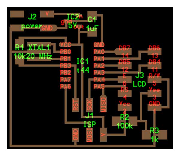
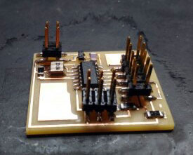
Milling and Soldering
Programming
For programming, I downloaded the files ".make" and ".hex" on the output week page section dedicated to the LCD and using the AVRRISP to bootload the board.
Initially I got a red light from the AVR and quickly understood I had problem with 9v regulator that was almost dead providing 2v.
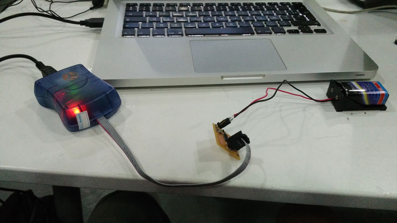
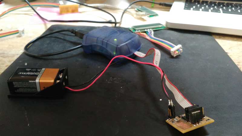
By changing with a full powered battery, the green light turned on.
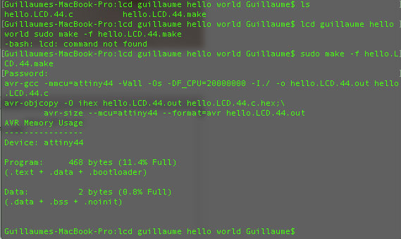
For the programming of the LCD we wrote as super user on the console the following:
sudo make -f hello.LCD.44.make
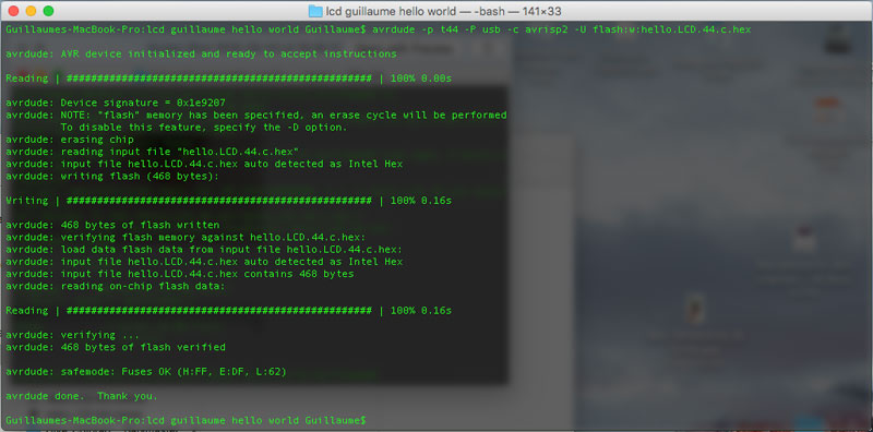
Now we write on the console the following:
avrdude -p t44 -c avrisp2 -U flash:w:hello.LCD.44.c.hex
Then just need to connect the LCD display to the righ pins.
In the Week#17 - network and communication, I will connect it to the Aquaduino via I2C
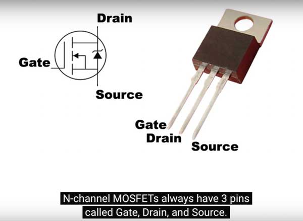
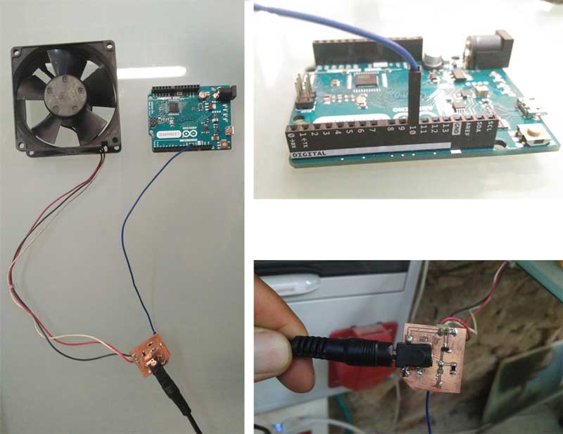
Power Control: Arduino Leonardo + N-Channel MOSFET for a +12V Vent fan
An another output that will be control by the Aquaduino, will be a vent fan to provide some artificial wind to re-inforce the plants structure and make them stronger.
How does it work ?
This section aims to attempt to explain, in simple terms, what is going on. It is based on a very good tutorial on Bildr blog
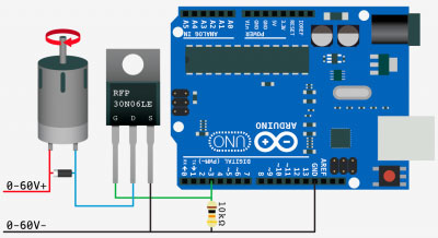
So we connect it so that our motor, solenoid or light is connected to V+ but not ground (V-). Ground is connected to the transistor’s drain. When our arduino sends a HIGH signal to the transistor’s gate, it switches the transistor (connecting the drain and source) and completes the circuit for the motor, solenoid, or light.
Hooking it up / What’s the diode used for?
This circuit is pretty simple. The only part that looks funny is the resistor. This is a pull-down resistor. The resistor holds the gate low when the aquaduino does not send a high signal. This is here incase the arduino comes loose, or the wiring is bad it will default to off. You don’t want this pin to ever be floating as it will trigger on and off.
You can see that in the above illustration, there is a diode parallel to the device we are powering. Any time you are powering a device with a coil, such as a relay, solenoid, or motor, you need this guy, and don’t leave home without it. What happens is when you stop powering the coil, a reverse voltage, up to several hundred volts, spikes back. This only lasts a few microseconds, but it is enough to kill our MOSFET. So this diode (only allows current to pass one way) is normally facing the wrong direction and does nothing. But when that voltage spikes comes flowing the opposite direction, the diode allows it to flow back to the coil and not the transistor. We will need a diode fast enough to react to the kickback, and strong enough to take the load. A rectifier diode like the 1N4001 or SB560 should do the job.
PWM pin, what's for ?
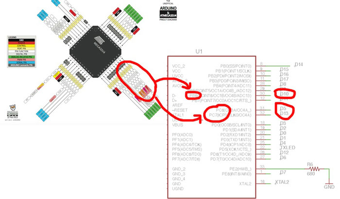
Arduino pin 10, which is a Digital PWM Pin (see following explanation) is used to turn the MOSFET on and off and in a the future, it will allow me to modulate the output power of the vent fan motor to regulate the wind strengh for the plants
Pulse Width Modulation, or PWM, is a technique for getting analog results with digital means. Digital control is used to create a square wave,
 a signal switched between on and off. This on-off pattern can simulate voltages in between full on (5 Volts) and off (0 Volts) by changing the
 portion of the time the signal spends on versus the time that the signal spends off. The duration of "on time" is called the pulse width.
 To get varying analog values, you change, or modulate, that pulse width. If you repeat this on-off pattern fast enough with an LED for example,
the result is as if the signal is a steady voltage between 0 and 5v controlling the brightness of the LED.
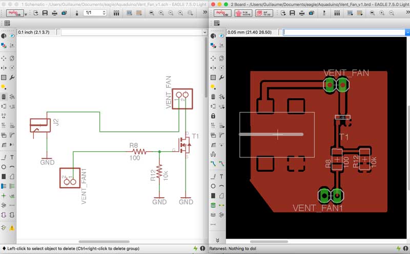
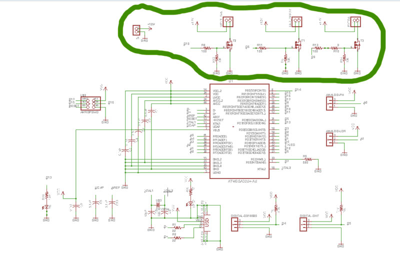
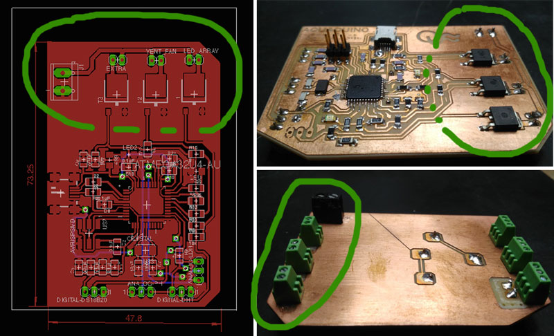
EAGLE // BOM // Layout
- A +12V CONN POWER JACK 2.1X5.5MM HI CUR
- A resistor of 10k Ω
- A resistor of 100 Ω
- A diode XXX
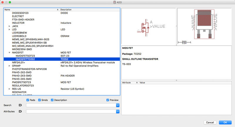
- A RFD16N05LSM9ACT-ND MOSFET N-CHANNEL 50V 16A (EAGLE: NMOSDFETTO252)
- A 3x1 Pins
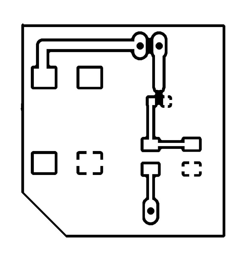

Milling and Soldering
Arduino Code
I load up the the sketch onto the Arduino Leonardo given on the Adafruit tutorial to control DC Motors
In the 'loop' function, the command 'Serial.parseInt' is used to read the number entered as text in the Serial Monitor and convert it into an 'int'. You could type any number here, so the 'if' statement on the next line only does an analog write with this number if the number is between 0 and 255.
/* Adafruit Arduino - Lesson 13. DC Motor
*/
int motorPin = 10;

void setup()
{
pinMode(motorPin, OUTPUT);
Serial.begin(9600);
while (! Serial);
Serial.println("Speed 0 to 255");
}


void loop()
{
  if (Serial.available())
  {
    int speed = Serial.parseInt();
    if (speed >= 0 && speed <= 255)
    {
      analogWrite(motorPin, speed);
    }
  }
}
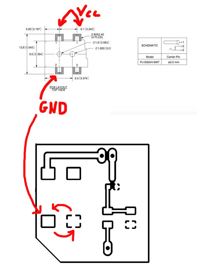
Magic happen
After connecting the board to the +12V power supply, nothing happen.... Looking at the PJ-002AH-SMT Jack Connector datasheet on Digikey, I realized that I didn't connect the right GND
Integrating the Power circuit directly on Aquaduino v0.1
Download
You access and download all the files generated during this week from my google drive: