Week #8 EMBEDDED PROGRAMMING
Assignment
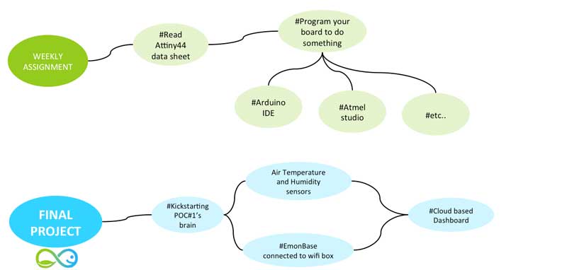
Week workflow
This is how I see my week
Softwares used
- Arduino IDE
- -
- -
Read a microcontroller data sheet
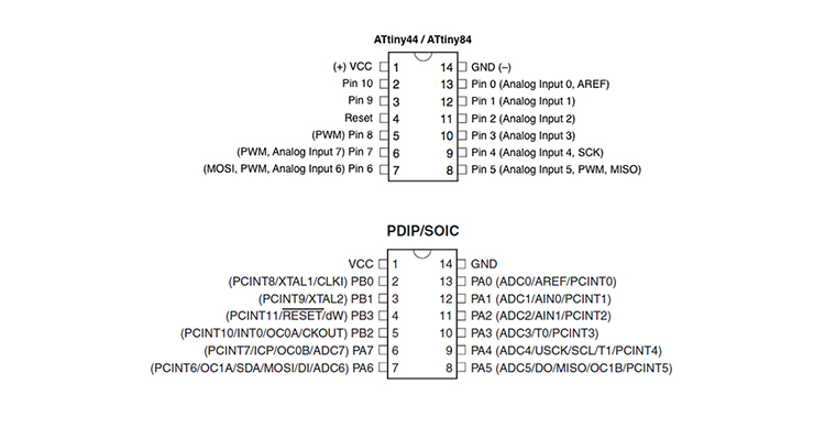
To design the board I refereed to the ATtiny Microcontroller Pin-Outs scheme showing the parallels between the ATtiny44 and Arduino given on High Low Tech programmer web site. Studying the ATtiny Microcontroller datasheet as rewquired that week I started comparing Pin's.
Program your board to do something
Using Arduino IDE
When it came to programming the actual board using the Arduino IDE, I followed the instructions given in a tutorial on High Low Tech. This page links to the Atmel ATtiny library for Arduino, explains how to install it, and how to set up the parameters for programming. It also shows a very handy diagram showing the parallels between the ATtiny44 and Arduino, needed to put the right pin references into the code.
Once the ATtiny library has been installed, I followed the workflow described below
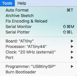
Workflow:
        - Go to Tools / Select Board "ATtiny" / Processor "ATiny44 / Clock "20 Mhz" (external")
        - Click on Burn bootloader
As expected ... I get my first error message mentionning issues regarding my connections
Troubleshooting
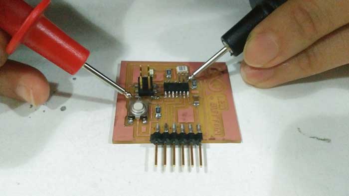
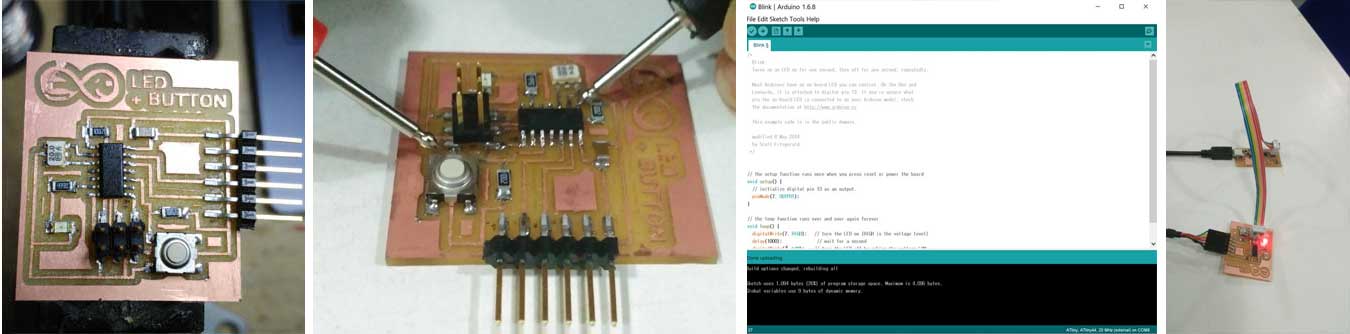
Using the multimeter, I've discovered that on FTDI pin was not solder properly. After fixing it, I restart the "Burn bootloader" again and it works !!!
Victory !!!
As a first test to program the board, I run the blinks sequence on the LED example given by Arduino. This worked instantly as I pushed the code onto the board. I literally jumped up and shouted out a victory cry when I saw the LED lighting up in the sequence I wrote! It was truly an amazing moment, I saw my whole project coming into sight!
For the final project the button will be changed with a potentiometer to light the Aquaponic LED lighting system at varying brightnesses (i.e. Fig 7)
Writing my own code
Final Project evolution
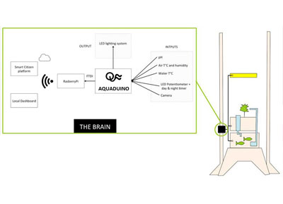
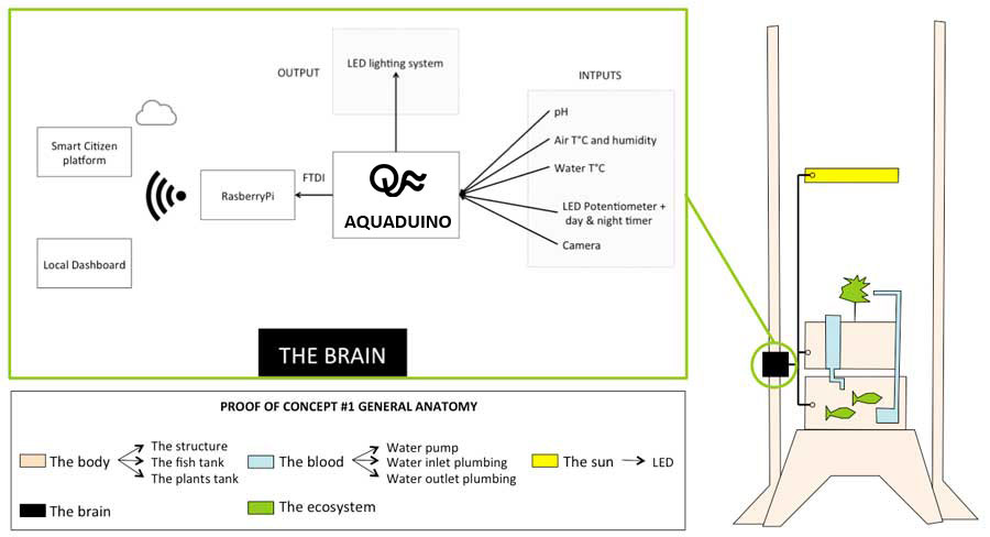
POC#1's brain architecture
This weekly assignment helps me start thinking about the electronic architecture of the aquaponic system "Brain". Which sensor should I develop first ? How do I design the electronic architecture leveraing already developed sensors & Fabduino from last years Fab Academy students ? How do I consider their compatibility with already comercial parts such RasberyPi ? What are the data I would like to keep loally and what are the one I would like to send to the cloud ? Which platform should I consider to send my data having in mind scalability if a business can start from this POC ? etc
Fortunately, I meet our in-house electronic genius Guillem from the Smart Citizen team that tremendously help me answering these questions and drawing the following electronic architecture
Starting with the Air T°C & Humidity sensors + Dashboard
Last year, I built an Open Energy Monitor system based on Arduino at home, to measure my electricity consumption. I decide to reused some parts of this project to start the "brain" construction with:
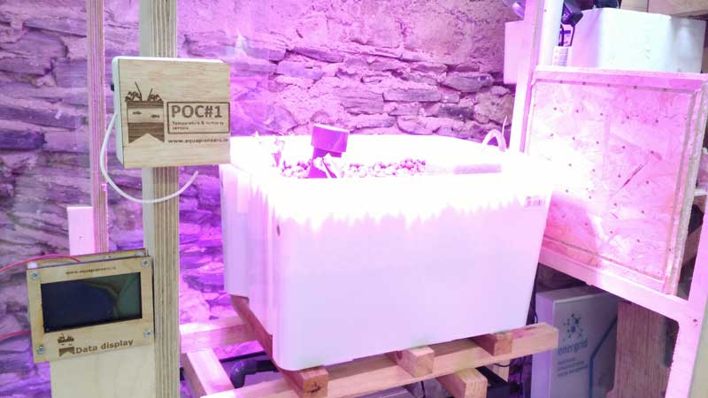
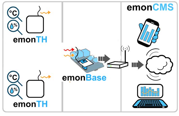
Now that the Temperature and Humidity sensor data values are registered in the cloud-based data base, these data can viewed in dashboard as shown in Fig.10
Download
You access and download all the files generated during this week from my google drive:
Conclusion
I was completely new to Electronic design and it has been a great introduction week. One of the great learning of this week is about the settings you need to take care (i.e. grid settings, net settings ) before starting editing the traces on the board. What's more, it is essential to adapt the Design Rules according to your local machine / tools and check if DRC are all respected before exporting your your file.